Page is loading ...

Installation, se & Care Guide
30" and 36" FreeoStandin 9 Range Hood

i_i!_!_i!i_iii_!i!_!_i!i_iii_!i!_!_i!i_iii_!i!_!_i!i_iii_!i!_!_i!i_iii_!i!_!_i!i_iii_!i!_!_i!i_iii_!i!_!_i!i_iii_!i!_!_i!i_iii_!i!_!_i!i_iii_!i!_!_i!i_i__i@2007 ElectrduxHome Products, Inc. All rights reserved. Printed in Mexico

important Safety instructions
mmpo ant Safe mnstructions
Read all instructions before using this
appliance.
Save these instructions for future
reference.
Approved for residential appliances
For residential use only
Do not attempt to installor operate your appliance
until you have read the safety precautions inthis
manual. Safety items throughout this manual are
labeled with a WARNING or CAUTION based on the
risk type.
WARNmNG
This symbol alerts you to
situations that may cause
serious body harm, death
or property damage.
This symbol alerts you to
situations that may cause
bodily injuryor property
damage.
PLEASE READ ENTIRE INSTRUCTIONS BEFORE PROCEEDING.
INSTALLATION MUST COMPLY WITH ALL LOCAL CODES.
IMPORTANT: Save these Instructions for the Local Electrical Inspector's use.
INSTALLER: Please leave these Instructions with this unit for the owner.
OWNER: Please retain these instructions for future reference.
Safety Warning: Turn off power circuit at service panel and lock out panel, before wiring this appliance.
Requirement: 120 V AC, 60 Hz. 15 or 20 A Branch Circuit

_i_!_i_i!_i_!!!_ii!_i_!!_i_!!_!i_!_!_i_i!_!_i!_!_i!_!_i!_!_i!_!_i!_i_!_!_i_ii_!_!_ii_!_iiiii_!J_i_!_i_i_i_i_i_i_i!!_!i!i_!_!i!_!_ii_i_i_
; Important safety Instructions
READ AND SAVE THESE INSTRUCTIONS
mmpoAant safety mnstructions
RA_tko_fa:,jcua._ly OcPoe_na:ectdFDOeVIATiNGUSE ONLY DO NOT USE e-TrOsRp_y BeeTohree
[O_X_g_ZARDOUSOREXPLOS,VEMATER,- , _ow
• Servicing.
.... WA _ N _N G Th sun t s equpeed w th ntegra d sconnect ng sw tch
located inside the b!ower housing
TO REDUCE THE RiSK OF FIRE ELECTRIC SHOCK
OR INJURY TO PERSONS, OBSERVE THE FOL- _ WARNmN_
LOWING: _ _ _
A. Use this unit only in the manner intended by the manu- TO REDUCE THE RISK OF A RANGE TOP GREASE
facturer. If you have questions, contact the manufac- FIRE.
turer, a) Never leave surface units unattended at high settings.
B. Before servicing or cleaning the unit, switch power off Boilovers cause smoking and greasy spillovers that may
at service panel and lock service panel disconnecting ignite. Heat oils slowly on low or medium settings.
means to prevent power from being switched on acci- b) Always turn hood ON when cooking at high heat or
dentally. When the service disconnecting means can- when flambeing food (I.e. Crepes Suzette Cherries
not be locked securely fasten a prominent warning Jub ee Peppercorn Beef F ambe')
device such as a tag to the service panel, c) Clean ventilating fans frequently. Grease should not
C. Installation Work and Electrical Wiring Must Be Done be allowed to accumulate on fan or filter.
By Qualified Person(s) In Accordance With All Appli- d) Use proper pan size. Always use cookware appropri-
......................................................................................................cable Codes & Standards, Including Fire-rated Con- ate for the size of the surface element.
struct_en.
i_i!_!_i!i_ii_!i!_!_i!i_ii_!i!_!_i!i_ii_!i!_!_i!i_ii_!i!_!_i!i_ii_!i!_!_i!i_ii_!i!_!_i!i_ii_!i!_!_i!i_ii_!i!_!_i!i_ii_!i!_!_i!i_ii_!i!_!_i!i_i

and o_inances.
Ifcodes permit and a separate ground wire is used, it
is recommended that a qualified electrician determine
that the ground path is adequate.
Do not ground to a gas pipe.
Check with a qualified electrician ifyou are not sure
range hood is properly grounded.
Do not have a fuse in the neutral or ground circuit.
iMPORTANT
Save Installation Instructions for electrical inspector's
use.
Qualified Installer, check ifthey perfectly fit with
your cabinet/wall.
4, Do not use flex ducting.
, COLD WEATHER installationsshould have an
additional backdraft damper installed to minimize
backward cold air flow and a nonmetallic thermal
break to minimize conduction of outside
temperatures as part of the ductwork. The
damper should be on the cold air side of the
thermal break.
The break should be as close as possible to
where the ducting enters the heated portion of
the house.
The range hood must be connected with copper wire
only.
The range hood should be connected directly to the
fused disconnect (Or circuit breaker) box through
metal electrical conduit.
Wire sizes must conform to the requirements of the
National Electrical Code ANSI/NFPA 70 -- latest edi-
tion*, or CSA Standards 022.1-94, Canadian Electri-
cal Code Part 1 and 022.2 No. 0-M91 - latest edi-
tion** and all local codes and ordinances.
6_
Make up air: Local building codes may require the
use of Make-Up Air Systems when using Ducted
Ventilation Systems greater than specified OFM of
air movement.
The specified OFM varies from locale to locale.
Consult your HVAC professional for specific
requirements in your area.
A U.L.- or C.S.A.-listed conduit connector must be
provided at each end of the power supply conduit (at
the range hood and at the junction box).
Copies of the standards listed may be obtained from:
* National Fire Protection Association Batterymarch Park Quincy,
Massachusetts 02269
** CSA International 8501 East Pleasant Valley Road Cleve-
land, Ohio 44131-5575

_!_!_!;;i!_!_i_!_!_i_!_!_i_!_!_i_!_!_i!:;_ii!!_ii!!_i_!i_!i_!i!ii_!i_i_;_i_i!_!!_i_!_ii_!i_i_:i_:i_:i_!_:i_i_i_i_i!_!ii_!i
List of Materials
List of Materials
Hoodcanopyassemb]ywithb]ower, transition.
• Lampalreadyinsta]led.
Grease filter.
• GlassCanopy
• Duct cover.
• mardwarebagwith:
• PlasticGasket.
- Template.
• Uuctcoversupportbracket (1 piece)
• Use, careand installationguide
• Glassbracket(2 pieces) ....
• Woodscrews(6 pieces-3/16 x 1 3/4)
• Hoo,dattachmentanchorsscrews(6pieces-
. 1/s xs/s)
Assemb]yscrews(Spieces)
.....
Recirculation KIT
• Charcoa]filter
i_i!_!_i!i_ii_!i!_!_i!i_ii_!i!_!_i!i_ii_!i!_!_i!i_ii_!i!_!_i!i_ii_!i!_!_i!i_ii_!i!_!_i!i_ii_!i!_!_i!i_ii_!i!_!_i!i_ii_!i!_!_i!i_ii_!i!_!_i!i_i

installing the hood
mnstaHing the hood
0
0
Forthe most efficient air flow exhaust, use a
straight run or as few elbows as possible.
Vent unit to outside of building, only.
On avarage 2 to 3 hours are necessary to com-
plete installation (without considering cut to be
done on wall and or on cabinet, installation of
ducts, conduit and electrical connections to the
mains).
The hood isfitted with Screws and Drywall
Anchors suitable for most surfaces, consult a
Qualified Installer, check if they perfectly fit with
your cabinet/wall.
Do not use flex ducting.
COLD WEATHER installationsshould have an
additional backdraft damper installed to minimize
backward cold air flow and a nonmetallic thermal
break to minimize conduction of outside
temperatures as part of the ductwork. The
damper should be on the cold air side of the
thermal break.
The break should be as close as possible to
where the ducting enters the heated portion of
the house.
Make up air: Local building codes may require the
use of Make-Up Air Systems when using Ducted
Ventilation Systems greater than specified CFM of
air movement.
The specified CFM varies from locale to locale.
Consult your HVAC professional for specific
requirements in your area.
Typical installation
Min installationheight from the range top to the
bottom of the hood is 30" if a gas range is used
or 24" to 30" if an electric range is used.
These hoods are not recommended to be used
over indoor grills.
The hood may be installed onto a wall and vented to
the outdoors, or it can be installed for recirculating
operation (recirculating accessories not supplied with
the hood).
This hood can be installed over any electric and gas
cooktop/range.
It can not be installed over any profe88ional
cooktop / range.
Ins! lling preparation
Advance planning
• Determine the exact location of the vent hood.
Plan the route for venting exhaust to the
outdoors.
Use the shortest and straightest duct route
possible.
Refer to "Ductwork installation guidelines"
paragraph for further informations.
Install a wall cap with damper or roof cap at the
exterior opening. Order the wall or roof cap and
anytransition needed in advance.
Use 8" round metal ductwork only.
Wall framing for adequate support
= This vent hood isheavy.
'Adequate structure and support must be
provided in all types of installations. The hood
must be secure to vertical studs in the wall, or to
a horizontal support.
The vent hood should be on site before final
framing and wall finishing. This will help to
accurately Iocatethe duct work and electrical
service.
Installation will be easier if the vent hood is
installed before the cook-top and countertop are
installed.
Removing the packaging
Remove carton carefully, Wear gloves to protect
against sharp edges.
Remove the protective film covering the product
before putting intooperation.

Keepductrunsasshortandstraightaspossible.
Ductfittings(elbowsandtransitions)reduceairflow
efficiency.
• Theheightinstallationisdeterminedbythe
followingimage.Markthelocation.

installing the hood
Mounting the duct cover bracket
The duct bracket should be installedagainst the
back wall and flush with the ceiling. This bracket will
hold the telescopic duct cover in place at the top
(this a extra accessory available not included with the
hood).
Secure the bracket to the wall:
• Align the marked centerline on the bracket with
the centerline on the wall.
Mark 2 screw hole locations in the wall.
Drill5/16" pilot holes in the marked locations.
Install wall fastener anchors.
Drive wood screws, by hand, into the fastener to
allow anchors to expand. Remove the screws.
Secure the bracket to the wall with wood screws
and/or fasteners.
J
/
i
d)
/
Ceiling ducting
If the duct will vent straight up to the ceiling:
Use level to draw a line straight up, from the
centerline on the template to the ceiling.
Measure at least 4 -12/16 "from the back wall to
the circle center of an 8-1/2"hole on the ceiling.
Wall ducting
If ductwork will vent to rear:
Use a levelto draw a line straight up from the
centerline on the template.
Measure at least 23 - 12/16" (the measure might
vary depending on the elbow used) above the
pencil line that indicates the bottom installation
height, to the circle center of an 8-1/2,diameter
duct hole (Hole may be elongated for duct elbow).
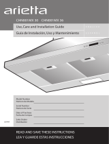
House wiring location
= The junction box islocated on the top leftside of
the hood.
• Wiring should enter the back wall at least 20"
above the bottom of the installation height, and
within 5-7/8" and 4-7/8"of the left side of the
centerline.
-=.t_Lf------'_ - FORCEILINGVENTDUCTING
4-3/4"circle
center to wall _ / i
WALL._( _ Circlecenterat233/4"
VENT \ J" _0ve the marked bottom
DUCT _J pencil line.
o o
Horizontalstraight
pencilline

i_i!_!_i!i_ii_!i!_!_i!i_ii_!i!_!_i!i_ii_!i!_!_i!i_ii_!i!_!_i!i_ii_!i!_!_i!i_ii_!i!_!_i!i_ii_!i!_!_i!i_ii_!i!_!_i!i_ii_!i!_!_i!i_ii_!i!_!_i!i_i

installing the hood
• Removethe hood.
Drive "lower" wood screws, by hand. Remove
screws.
Mount the hood onto the "upper" screws.
Drive and tighten the "upper" wood screws, by
hand.
Drive and tighten the "lower" wood screws, by
hand.
Installthe plastic gasket to the front hood flange.
J

i_i!_!_i!i_ii_!i!_!_i!i_ii_!i!_!_i!i_ii_!i!_!_i!i_ii_!i!_!_i!i_ii_!i!_!_i!i_ii_!i!_!_i!i_ii_!i!_!_i!i_ii_!i!_!_i!i_ii_!i!_!_i!i_ii_!i!_!_i!i_i

installing the hood
Making the electrical connections
Electrical Shock Hazard
Warning: Turn off power at the service panel before
wiring this unit.
120 VAC, 15 or 20 Amp circuit required.
ELECTRICAL GROUNDING INSTRUCTIONS
THIS APPLIANCE IS Flqq-EDWITH AN ELECTRICAL
JUNCTION BOX WITH 3 WIRES, ONE OF WHICH
(GREEN/YELLOW) SERVES TO GROUND THE
APPLIANCE. TO PROTECTYOU AGAINST
ELECTRIC SHOCK, THE GREEN AND YELLOW
WIRE MUST BE CONNECTED TO THE
GROUNDING WIRE INYOUR
HOME ELECTRICAL SYSTEM, AND IT MUST
UNDER NO CIRCUMSTANCES BE CUT OR REMO-
VED.
Failure to do so can result in death or electrical
shock.
• Remove junction box cover and knockout on the
top left side.
Junction box
cover
If not already done, install 1/2" conduit connector
in j-box.
House
wiring
U.L listed
wire
electrical
conduit
Run black (live),white (neutral), and green (earth)
wires (#14 AWG) according to the National
Electrical Code or CSA Standards and local
codes and ordinances in 1/2" conduit from power
supply to j-box.
Connect black, white, and green wires from
power supply to black, white, and green/yellow
wires in j-box respectively.
These connections should be done always
making reference to the electrical diagram found
inside the hood.
Close j-box cover and reapply screws.
Mounting the glass canopy
= With the hood mounted on the wall slide the glass
canopy over the glass supports.
Insert the glass brackets.
Insert two screws into the bracket holes, drive the
screws by hand.

_!_!ii:i_iiii_i_ii_!_!i_i;;_i!_ii_;!_;!_i_i_!_!;i;i;i_!_i_i_i_i_i!;!i;i_ii;_i_ii;_ii_!_ii_ii!_!_;_i_i_i_i_i!!_;ii_;:iii_i_
lo ta,iog .ood
Mo,,,,t_,,Qt_,_,J,.,_,_o,,,,_ • _ecuret_ebottomoft_eductwit_assemb,_
screws prov ded
Position the duct cover over the mounted hood.
• Slide the bottom of the duct onto the glass area.
• Position the top of the duct over the duct = =
mountingbracket. Ifatelescopicductcoveris L
used, grab the upper part of the telescopic duct --
cover, pull itand place it intheductcover
mountingbracket. _- b.
• Secure the top of the duct with 2 assembly _
screws provided. :-
-\
\, i
\
.\
..... Install the grease filter and turn power on at service
panel. Checkoperationofthe hood.
i_i!_!_i!i_ii_!i!_!_i!i_ii_!i!_!_i!i_ii_!i!_!_i!i_ii_!i!_!_i!i_ii_!i!_!_i!i_ii_!i!_!_i!i_ii_!i!_!_i!i_ii_!i!_!_i!i_ii_!i!_!_i!i_ii_!i!_!_i!i_i

®

;!_!!i_!i_!:!_ii_:_i_:_iJ_i!i_%_!_i_i_!_!_i_i:_i_!_!_i_i!_!_;_
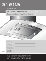
control buttons
control bu ons
Th_shood_s_qu_ppedw_thane_ectron_emotorand * fthefansatseeondspeedandthe"V'
amp centre . . -'.
. .' ......... button Is pressed, the fan wtl be set to first
/he control IS alole ]:o se[/4 alTrerent Tan speeas turn
speea
ON/OFF ght and has a t met funct on ,,--,
::::: • Ifthefanisatthirdspeedandthe V key is
::: Inthefollowingdrawingaredescribedthemainkey pressed, thefanwtl besettosecon, dspeed.
• Vfunctions • f the fan s at fourth speed and the
button is pressed, thefan will be settothird
::: speed ,
1\ 2 3 f f • If the fan is OFF and the "V' button is
\ / ," / / pressed the control backlight will light up.
@@ @@
5, " " Button. Seed Increase / ON
.A p
1. Li htButton Thisbuttonisusedtoincreasethefanspeed,
Q ortum ON thefan.
• Presslamp buttontoturnONthe light (Lamp • ThefanwillturnON ifthe"j_" button is
statepreviouslyOFF), pressedandthehoodwas'O_R "A"
: • Press lamp button to turn OFF the light (Lamp • If the fan is at first speed and the button
statepreviouslyON), ispressed, thefanwillbesettosecond
..... 2, Timer Button speed•
• Thedefaulttimersetting is 10 minutes, and it • Ifthefan isat second speed andthe "A"

i
Specia functions
Clockprogram.,ing
The clock can be reprogrammed at any time except during an active timed function.
• The clock can be displayed in a twelve hour format and valid clock times are from 1:00 to 12:59.
• The clock can be reprogrammed pressing the "Timer' button for 5 seconds, and after, the clock can be
adjusted with the "A"and "V'_butt°ns' Colon ":'"will flash indicating clock programming mode.
• The user can have minute increments / decrements of 1 minute, but ifthe user keep pressing the "A"/
'V' buttons for more than 1 second, the increments / decrements will be of 5 minutes.
During this option the control will round to the nearest 5 minutes. ,,
• The user can finish on reprogramming the clock pressing the Timer button.
• After 1 minute of no button pressed the control will accept the programmed clock time and will add one
minute to the set clock.
Grease filter saturation alarm
• After thirty fan functional hours, the display will show "Grease Filter" ifthe fan is active.
When this icon is shown in the display, the grease filters installed are required to be washed.
To reset the grease filter saturation alarm the user must press the "_" button for 5 seconds, after this
action the icon "Grease filter" is not displayed, and the hood has the normal display operation.
Charcoal filter saturation alarm {Recirculating accessories)
• After one hundred and twenty functional hours of the fan, the display will show "Charcoal Filter" ifthe fan
is active. When this icon flashes on display, the charcoal filters installed are required to be replaced or
reactivated.
To reset the charcoal filter saturation indication the user must press the "V" button for 5 seconds, after
this time the icon "Charcoal filte¢' is not displayed and the hood has the normal display operation.
Audible signal activation and deactivation
• The audible signals can be activated or deactivated pressing the "Light" button for 5 seconds.
Ifthe audible signal is activated, a tone must sound and the "Snd" symbol must appear on the display for
2 seconds.
Ifthe audible signal is deactivated, the "Snd" symbol must appear on the display for 2 seconds and no
tone must sound.
Charcoal filter inclusion and exclusion {Recirculating accessories)
• The charcoal filter inclusion or exclusion can be set by pressing the "V" and "_" buttons at the same
time for 5 seconds.
The Inclusion or exclusion of charcoal filter must be selected while the lamps and the motor are OFF.
When the charcoal filter has been excluded, the charcoal filter alarm is disabled.
Heat sensor
The control isequipped with a heat sensor that will turn on the blower at second speed if excessive heat
occurs (over 158 ° For 70°0) surrounding the control area.
Ifthe blower is OFF or if it is operating at first speed, the blower will be set automatically to second speed,
the display shows the word "CARE"to indicate that heat sensor has detected an excessive heat.
During this state, the user may raise the blower speed to third speed but can not decrease the speed.
When the temperature level on the hood drops to normal, the blower will operate in the setting defined by
the user before the alarm occured.

For Best resuks
iiiiiiiiiiiiiiiii{ii{ii{ii{ii{ii{!i_iii!!i_!!ii_iii_iii_!iiii_!iiii_!_!i_!!i!_ii{!_!_ii_!_ii_i_i• Continuous use of the fan system while cooking helps keep the kitchen comfortable and less humid.
_i_ii!i!i__iJ_iii!iii!ii{!!i!!i!!i!!i!!!_i!!iii_ii_ii_!_i_i!!i__iii_!_!___iii___iii___ii__i!i_i!i{i_iii!_!_!• Italsoreducescookingodorsandsoiling moisturethatcreateafrequent needforcleaning.
:_iiii_i!_!_!_!i!i_iii!i_i!_!!_ii_ii_ii_ii_ii_i_i_i_!_!!_!_!_i!i!i_i!i_!i_i_ii!_!_i!i_i:i_i{!!_i!_i!_iii!_!iii!iii_!!• Turnthebloweron beforestartingtocook.
:_iiiii_!ii___i_i___i_i_!_i_i_!_iii_!i!ii_!i!ii_!i!ii_!i!ii_!i!_i_!_!!i____i_ii!_!__i_i!i!i!___!ii!_i_!i!_i_!i!___!_i_i_i_!_!_!_!_!!_!__i___i_!_!_• Usearearburnerwhen browningorpanfrying meat.
_:_iiii:iiii:iii_iiii_i_i_iii!!!_i!!_!_i!!i!!i!!i!!i!!i!!i!!i!!_!_!i_!_i{_i_!!_!!_i!_{!_!!i_{{i• Open a window or inside door slightly.
_:iiii:iiii:iii_i{i_iiii_iiii_ii____i!i!___i___i_:!!_i_iii_iii_iii_iii_i{!:{_i_i:__ii!_ii!_ii!_ii!i__ii_!i___i_i_{• Clean the filters and the wall behind the filters frequently.
i:iiiii:iiii:iii_iiii_iiii_iiii_iiii_iii!_{i_i!_i_iii!__!__!__!__!_i:__!i_i:_i_i___iJ_iii!_i_iiiiii_i!i________i:_i__i_• Theblowershould beturnedonforafewminutesbeforecooking inordertoestablishaircurrentsupward
i:iiii:iiii:iii}iii}iii}iii}iii}ii_!i_____i_i_____i!__!i__!i__!i__!i__!i__!iiiiiiii__!i!_!i{ii_i!___!ii!:i!!:___i_:i_____iithroughthehood. Thuswhenheat, smoke, moisture, greaseandcookingodorsareproduced, theywill
:iiiii__i{iiiiiiiii:i_i:i_iii__i!__i_____i_____i_____i_____i_____i_____i_____iii!!i_i__i!i:i!i!___!!ii_i!!ii_i!!__i!_becarried outside instead of drifting intootherrooms.
:iiiii__i__iiiiiiiiiiiiiiiii:_i:_i:_{iiii__i_i_!__!__i__!__i__!__i__!__i__!__i_!_!i__iii____i__!_!i!!i_!:_!_!_• Usethelowspeedsfornormal useandthehigherspeedsforstrongodorsorfumes.
:iiii_______iiiiiiiiiii:!ii:!ii:!ii:!ii_iii_i!ii_i_i_!ii_!_!ii_!_!ii_!_!ii_!_!ii_i!!!ii_ii!i_{__!_ii!!i• Uraftsacrossthe rangeorcooktopwill causetheescapeofheat, smoke, moisture, greaseand cooking
_:_ii__:_i__:_i_iiiiiiiiiiiiiiiiiiiiiiiiii_:!_ii_:!_ii_:!_ii_:!_i!:!iii!!_!i!!i___i___!_i__i__i__{_i_i_i_i_!iodorsfromthe hood. Such draftsshould be prevented in sofaras possible.
_i_ii__:_i__:_i_iiiiiiiiiiiiiiiiiiiiiiiii!_i!ii!_i!ii!_i!ii!_i!_!_ii_!_!i!_i_!i!i!!_!i!i!i_i!{_i{_i{iii___• The best job of ventilation in the kitchen is done where the only air currents are those created by the
bloweritself.
i_iiii_!_!!_ii!!_i_i_i_i_i_ii!{{{!ii!ii!_!{_!ii:_!_!i!i!i_i_!i_i_i• ForGasOooktops, alowerblowerspeedshould beusedif:
:!{ii!jilili!i!ii!ii!ii!ii!ii!ii!ii!i!ii!i!iiiii!ili!iii!{iiii!ii{ili!!• the gas flame is being distorted by the air movement.
_!_i%!i_Ji!ii!_i!!_ii!_ii!_ii!_!i_i!i!_!ii_!_ii_!_ii_!_ii!_!i!i!_!_i_!i_i_!i_i_!_i!!_!• theburnercontinuallysparks(clicks)
_!_i_iii_i_iii_i_ii_i_!_i_i_!_i_i_!_iii_ii_!_i!_iii!_i_i_i_i_i_i_iii!_!_i_!ii_ii:i_i!i_{i!_i_ii!_i_ii!_i_!!_!_i_i_i_i_!_• theburnerflamerepeatedlyblowsout.

Care and cleaning
Care and cleaning
The efficiency of the range hood system depends on
the cleanliness of the intake and filters.
The frequency of cleaning depends on the amount
and type of cooking.
• Do not use the ventilating system without the
filters in place or with grease-laden filters or
surfaces.
To avoid risk of fire and explosion do not use
flammable liquids or solvents.
Always unplug or disconnect the appliance from the
power supply before servicing.
Be sure the entire hood (including the filters and light
bulbs) has cooled and grease has solidified before
attempting to clean any part of the appliance.
Filters
The metal grease filters are made of stainless steel
anodized aluminum and are long lasting.
To Remove The Metal Grease Filters
Turn the fan and lights off.
Pull the spring release handle.
Lights
Before replacing the lamps, switch power off at
service panel and lock service panel disconnecting
means to prevent power from being switched on
accidentally.
NOTE: -rum off the lights and fan. Allow the lights
to cool before handling. If new lights do not
operate be sure lights are inserted correctly before
calling service.
Replace Lights
Remove the innerlamp lens cover by insertinga
small flat blade screwdriver intoeach of the three
slots and gently prying itfree.
NOTE: Do not remove the outer trim ring (lamp
assembly).
Grasp the bulb and pull it straight out.
Replace with 12 volt, 20 watt halogen bulbs with
a G4 base SUITABLE FOR USE IN OPEN
LUMINAIRES.
Follow package directions, wear gloves, do not
touch bulb with your bare fingers.
To Replace The Metal Grease Filters
Reverse procedure.
To Clean Filters
o It isrecommended that the filters be washed at
least once a month; they can be washed by hand
or inthe dishwasher.
Drain water through edge holes and let each filter
dry thoroughly before replacing it.
Replace innercover by insertingthe three
retaining tabs intothe three slots and pressing
them firmly in place.

i_i!_!_i!i_ii_!i!_!_i!i_ii_!i!_!_i!i_ii_!i!_!_i!i_ii_!i!_!_i!i_ii_!i!_!_i!i_ii_!i!_!_i!i_ii_!i!_!_i!i_ii_!i!_!_i!i_ii_!i!_!_i!i_ii_!i!_!_i!i_i
/