Page is loading ...

I
BIBUS 2
nd
Ed. VOP - Technical Manual
II ED. VOP
INDEX
BIBUS II^ Ed. VOP
INDEX - BIBUS II^ Ed. VOP
http://www.urmetdomus.com
e-mail:[email protected]
MT 124-013G (Rev. January 2010)
II ED. VOP

II
BIBUS 2
nd
Ed. VOP - Technical Manual
II ED. VOP
INDEX
BIBUS II^ Ed. VOP
INDEX - BIBUS II^ Ed. VOP

III
BIBUS 2
nd
Ed. VOP - Technical Manual
II ED. VOP
INDEX
BIBUS II^ Ed. VOP
INDEX - BIBUS II^ Ed. VOP
n
e
W
NEW
(Index at the beginning of section)
BIBUS SYSTEM
Sec. 1
(Index at the beginning of section)
START
PROGRAMMING
Sec. 1A
(Index at the beginning of section)
CALL MODULE
Mod. Sec. 2A
(Index at the beginning of section)
Mod. Sec. 2B
(Index at the beginning of section)
PANEL WITh DOOR UNIT AND DIGITISER
Mod. Exigo Sec. 3G
(Index at the beginning of section)
Mod. 1128
Sec. 3F
(Index at the beginning of section)
Mod.
Sec. 3A
(Index at the beginning of section)
Mod.
Sec. 3B
(Index at the beginning of section)
Mod. 725
Sec. 3C
(Index at the beginning of section)
APARTMENT DOOR PhONES STATION Sec. 4A
(Index at the beginning of section)
APARTMENT VIDEO DOOR PhONE STATIONS Sec. 4B
(Index at the beginning of section)
CONCIERGE SWITChBOARD Sec. 4C
(Index at the beginning of section)
COUPLERS - POWER UNITS - VARIOUS DEVICES Sec. 5
(Index at the beginning of section)
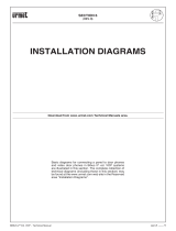
INSTALLATION DIAGRAMS Sec. 6
(Index at the beginning of section)
SPARE PARTS FOR RETROFIT Sec. 7
(Index at the beginning of section)

IV
INDEX
BIBUS II^ Ed. VOP
INDEX BIBUS II^ Ed. VOP
BIBUS 2
nd
Ed. VOP - Technical Manual
II ED. VOP
Product Description Sec. Pag.
788/22 Call repeater auxiliary relay ....................................................................................................................................5 ............. 10
788/52 Supplementary relay ...............................................................................................................................................5 ............. 11
789/2 Supplementary power supply .................................................................................................................................5 ................5
1032/65 Programming keyboard ..........................................................................................................................................5 ................8
1038/17 16-push button expansion module .....................................................................................................................3A ............... 4
3B ................4
3C ................4
3G ................4
1038/73 K-Steel additional alphabetic keyboard .............................................................................................................. 2B ................5
1038/74 Sinthesi additional alphabetic keyboard ..............................................................................................................2A ................5
1072/5 Loudspeaking unit with built-in digitalizer device Mod. K-Steel ......................................................................... 3B ................2
1072/7 Loudspeaking unit with built-in digitalizer device Mod. Sinthesi .........................................................................3A ................2
1072/13 Sinthesi calling module with repertory .................................................................................................................2A ................2
1072/14 K-Steel calling module with repertory ................................................................................................................. 2B ................2
1072/19A Loudspeaking unit with built-in digitalizer device ............................................................................................... 3C ................2
1072/24 Bus Coupler ............................................................................................................................................................5 ................2
1072/28 Loudspeaking unit ................................................................................................................................................3F ................2
3G ................3
1072/42 Concierge Switchboard ....................................................................................................................................... 4C ................2
1072/57 Cable for programming directories from the PC ....................................................................................................5 ................9
1072/58 Programming Kit Bibus 2
nd
ED ...............................................................................................................................5 ................9
1072/59 Supplementary three-tone ringing for Bibus ..........................................................................................................5 ............. 19
1072/60 Programming adapter.............................................................................................................................................5 ................8
1072/67 Bibus PABX interface .............................................................................................................................................5 ............. 14
1072/80 Special decoder......................................................................................................................................................5 ............. 11
1074/20 Video VOP power unit ............................................................................................................................................5 ................3
1074/54 VOPoorvideodistributor ....................................................................................................................................5 ................7
1074/55 VOP 4-user audio video distributor ..................................................................................................................New ............. 15
1074/90 Multipolar wire for VOP system .............................................................................................................................5 ............. 18
1082/40 Casing with front (Anthracite) ...............................................................................................................................3F ................5
1082/41 Casing with front (Grey) ........................................................................................................................................3F ................5
1090/850 Supplementary power unit 12Vdc - 15Vdc ............................................................................................................5 ................6
1128/1 Small push button ................................................................................................................................................3F ................5
1128/2 Large push button ................................................................................................................................................3F ................5
1128/5 Transparent module with tag for house number ..................................................................................................3F ................6
1128/30 Anthracite blank modules .....................................................................................................................................3F ................6
1128/31 Grey blank modules .............................................................................................................................................3F ................6
1128/44 Cases with front for outdoor house phone station (Anthracite) ...........................................................................3F ................2
1128/45 Cases with front for outdoor house phone station (Grey) ....................................................................................3F ................2
1128/51 Boxforushmounting .........................................................................................................................................3F ................9
1133/50 Table mounting kit for door phone Atlantico ........................................................................................................4A ................5
1134/50 Table mounting kit for door phone Utopia ..........................................................................................................4A ................9
1140/50 Table mounting kit for door phone Mod. Signo ................................................................................................New ................7
1143/51 ColouredlmforExigonametag(blue) .............................................................................................................. 3G ......... 9; 12
1143/52 ColouredlmforExigonametag(green) ............................................................................................................ 3G ......... 9; 12
1172/40 Basic door phones Mod. Atlantico .......................................................................................................................4A ................2
1172/42 Door phones with adjustable volume and mute function Mod. Atlantico ............................................................4A ................4
1172/43 Basic free hands door phone Mod. Utopia .......................................................................................................New ................2
1172/44 Basic door phone Mod. Utopia ............................................................................................................................4A ................6
1172/45 Door phones with multiple ringers and mute function Mod. Atlantico .................................................................4A ................2
1172/46 Utopia door phone with multiple ringers tones and mute function ......................................................................4A ................7
1172/50 Basic door phone Mod. Signo ...........................................................................................................................New ................4
1172/55 Comfort door phone Mod. Signo ......................................................................................................................New ................5
1172/63 Comfort free hands door phone Mod. Utopia ...................................................................................................New ................3
1202/954 Bracket for Atlantico ........................................................................................................................................... 4B ................4
1332/80 Power line protection device ..................................................................................................................................5 ............. 17
1332/85 Power line protection device ..................................................................................................................................5 ............. 16
1332/86 Powerlinelter .......................................................................................................................................................5 ............. 17
1702/1 Atlantico black and white video door phone white colour .................................................................................. 4B ................2
1702/40 Atlantico colour video door phone ...................................................................................................................... 4B ................3
1702/41 Atlantico black and white video door phone Anthracite colour .......................................................................... 4B ................2
1702/42 Atlantico black and white video door phone Grey colour ................................................................................... 4B ................2
1702/50 Colour mask kit for Atlantico ............................................................................................................................... 4B ................5
1702/92 Table mounting kit for Atlantico .......................................................................................................................... 4B ................4
1703/1 Utopia colour video door phone .......................................................................................................................... 4B ............. 11
1703/2 Utopia colour video door phone grey colour ...................................................................................................... 4B ............. 14
1703/37 Utopia colour video door phone white colour ..................................................................................................... 4B ............. 14
1703/51 FrontapsMod.Utopiayellow ........................................................................................................................... 4B ............. 20
1703/52 FrontapsMod.Utopiagreen ............................................................................................................................ 4B ............. 20
1703/53 FrontapsMod.Utopiaanthraciteblack ............................................................................................................ 4B ............. 20
1703/60 Flush mounting box for Utopia free-hands video door phone ............................................................................ 4B ............. 16
1703/61 Kit for Utopia free-hands video door phone installation on plasterboard walls .................................................. 4B ............. 18

V
INDEX
BIBUS II^ Ed. VOP
BIBUS 2
nd
Ed. VOP - Technical Manual
II ED. VOP
1703/95 Utopia free-hands video door phone bracket ..................................................................................................... 4B ............. 15
1703/137 Handset for hearing-impaired.............................................................................................................................. 4B ............. 20
1703/957 Utopia bracket (grey) .......................................................................................................................................... 4B ............. 12
1703/958 Utopia bracket (white) ......................................................................................................................................... 4B ............. 12
1705/1 Artico video door phone ...................................................................................................................................... 4B ................6
1705/101 Front glass smoky grey Mod. Artico ................................................................................................................... 4B ................8
1705/102 Front glass blue Mod. Artico ............................................................................................................................... 4B ................8
1705/954 Artico bracket ...................................................................................................................................................... 4B ................7
New ............. 13
1715/1 Arco black/white video door phone ..................................................................................................................New ............. 12
1715/50 Table mounting kit for Arco ...............................................................................................................................New ............. 13
1732/1 Scaitel video module ........................................................................................................................................... 4B ................9
1732/41 Scaitel colour video module ................................................................................................................................ 4B ................9
1732/56 Table mounting kit for Scaitel video module ....................................................................................................... 4B ............. 10
1732/957 Bracket for Scaitel video module ........................................................................................................................ 4B ............. 10
1740/1 Signo video door phone ....................................................................................................................................New ................8
1740/40 Signo colour video door phone .........................................................................................................................New ................9
1740/92 Table mounting kit for Signo .............................................................................................................................New ............. 10
1740/954 Signo bracket ....................................................................................................................................................New ............. 10
1742/13A Adapter device for tv camera ...............................................................................................................................3A ................4
3C ................4
3G ................6
1795/250 Extended differential video signal regenerator .......................................................................................................5 ................4
1795/40 VOP video distributor .............................................................................................................................................5 ................7
1810/40 Colour TV camera ................................................................................................................................................ 3G ................5
1810/70 B/W TV camera ................................................................................................................................................... 3G ................5
4311/13 Wireless call repeater .............................................................................................................................................5 ............. 20
9000/230 Security transformer ..............................................................................................................................................5 ................5
Mod. 725 Push button panel Mod. 725 components .......................................................................................................... 3C ................5
Mod. 1121-1721 Exigopushbuttonpanelfordedicatedush-mountingboxes ........................................................................... 3G ............. 10
Mod. 1143-1743 ExigopushbuttonpanelforSinthesiush-mountingboxes .............................................................................. 3G ................7
Mod. 1145-1745 Push button panel Mod. Sinthesi components ....................................................................................................3A ................5
Mod. 1155-1755 Push button panel Mod. K-Steel components .................................................................................................... 3B ................4
Product Description Sec. Pag.

VI
BIBUS 2
nd
Ed. VOP - Technical Manual
II ED. VOP
INDEX
BIBUS II^ Ed. VOP
INDEX - BIBUS II^ Ed. VOP

sec. new 2009
−−−−
1
ne
W
BIBUS 2
nd
Ed. VOP - Technical Manual
SECTION NEW 2009
NEWS
2009
Download from www.urmetdomus.com Technical Manuals area.
SECTION CONTENTS
BASIC FREE HANDS DOOR PHONE
MOD. UTOPIA Ref. 1172/43 2
COMFORT FREE HANDS DOOR PHONE
MOD. UTOPIA Ref. 1172/63 3
BASIC DOOR PHONE MOD. SIGNO
Ref. 1172/50 4
COMFORT DOOR PHONE MOD. SIGNO
Ref. 1172/55 5
SIGNO BLACK/WHITE VIDEO DOOR PHONE
Ref. 1740/1 8
SIGNO COLOUR VIDEO DOOR PHONE
Ref. 1740/40 9
ARCO BLACK/WHITE VIDEO DOOR PHONE
Ref. 1715/1 12
VOP 4-USER AUDIO VIDEO DISTRIBUTOR Ref. 1074/55 15

2
−−−−
sec. new 2009
ne
W
BIBUS 2
nd
Ed. VOP - Technical Manual
BASIC FREE HANDS DOOR PHONE MOD.
UTOPIA Ref. 1172/43
A
T1
B
T2
L
90 mm
195 mm
PERFORMANCE
Operation in 2nd edition systems only.
Conversation privacy function (single integrated decoder).
Speech signal activation button (hands-free) (B).
Two-tone door phone call.
Door opener button (A).
Auxiliary service key (T2).
Concierge call button (T1).
Speech signal active led (L)
Two-position adjustable call volume.
Ringer mute function with visual indication.
DESCRIPTION OF TERMINAL BOARDS
L1 Bus connection (not polarised)
L2 Bus connection (not polarised)
The maximum limit of door phones per column is 40 instead
of 50 in case of installation of a Bibus hands-free door phone
system. This also applies to mixed handset/hands-free systems.
TECHNICAL SPECIFICATIONS
Stand-by consumption: 1.6mA max.
Active voice consumption: 60mA max.
Working temperature range: -5 +45°C
Humidity: 90% RH at 30°C
PROGRAMMING
Perform the door phones queuing sequence on the call module or
on the concierge switchboard; then go in the apartment; keeping the
door lock release button pressed, press the speech signal activation
button.
Release the door lock release button and press again the speech
signal activation button.
The door phone will sound to indicate that it has been programmed.
•
•
•
•
•
•
•
•
•
•
§
OPERATION
On receiving a call, a voice connection can be established with the
visitor by pressing voice activation key. At the end of the connection,
press the same key to de-activate the voice connection.
The door opener button will operate the lock in the following cases:
For the entire conversation time.
Without hanging up for the programmed off-hook waiting time.
Calls can also be placed to the concierge in systems with
switchboard.
Activate the voice connection and press the concierge call button
(T1). Conversation with the switchboard will be established if the
switchboard answers within 10 seconds and the door phone line is
free. Otherwise, hang up and try again later. The switchboard will
store the call (if the device is on) in this case.
ADJUSTING CALL VOLUME
Red
MUTE
No calling tone
MIN
Minimum
calling volume
MAX
Maximum
calling volume
•
•
BASIC FREE HANDS DOOR PHONE MOD. UTOPIA
Ref. 1172/43
BASIC FREE HANDS DOOR PHONE MOD. UTOPIA Ref. 1172/43
PERFORMANCE - DESCRIPTION OF TERMINAL BOARDS
PROGRAMMING - OPERATION

sec. new 2009
−−−−
3
ne
W
BIBUS 2
nd
Ed. VOP - Technical Manual
COMFORT FREE HANDS DOOR PHONE MOD.
UTOPIA Ref. 1172/63
A
T1
B
T2
L
90 mm
195 mm
PERFORMANCE
Works in 2nd Edition systems only.
Conversation privacy function (single integrated decoder).
Door opener button (A).
Auxiliary service key (T2).
Concierge call button (T1).
Two-position door unit call volume.
Ringer mute function.
Supplementary ringer Ref. 1072/59 control.
Floor call button input.
Speech signal activation button (hands-free) (B).
Two-tone door phone call.
Speech signal active led (L).
DESCRIPTION OF TERMINAL BOARDS
L1 Bus connection (not polarised)
L2 Bus connection (not polarised)
C1 Floor call button input
C2 Floor call button input
S+ Supplementary ringer control positive
S- Supplementary ringer control negative
The maximum limit of door phones per column is 40 instead
of 50 in case of installation of a Bibus hands-free door phone
system. This also applies to mixed handset/hands-free systems.
TECHNICAL SPECIFICATIONS
Stand-by consumption: 1.6mA max.
Active voice consumption: 60mA max.
Working temperature range: -5 +45°C
Humidity: 90% RH at 30°C
Supplementary ringer control: V max=30Vdc
I max=40mAdc
PROGRAMMING
Perform the door phones queuing sequence on the call module or
on the concierge switchboard; then go in the apartment; keeping the
door lock release button pressed, press the speech signal activation
button.
Release the door lock release button and press again the speech
signal activation button.
The door phone will sound to indicate that it has been programmed.
•
•
•
•
•
•
•
•
•
•
•
•
§
OPERATION
On receiving a call, a voice connection can be established with the
visitor by pressing voice activation key. At the end of the connection,
press the same key to de-activate the voice connection.
The door opener button will operate the lock in the following cases:
For the entire conversation time.
Without hanging up for the programmed off-hook waiting time.
Calls can be made to the concierge in systems with concierge phone
or switchboard.
Lift the handset and press the concierge call button (T1).
Nothing will happen if the switchboard is off. Conversely, the door
phone will beep and the call will be sent if the switchboard is on. Two
possibilities may occur:
1. The switchboard answers within 10s or the door phone line is free:
a conversation with the switchboard is established.
2. The switchboard does not answer within 10s or the door phone
line is busy: the switchboard stores the call and the LED on the
door phone will ash after the 10s time-out. Hang up and wait for
the switchboard operator to return the call.
ADJUSTING CALL VOLUME
Red
MUTE
No calling tone
MIN
Minimum
calling volume
MAX
Maximum
calling volume
INSTALLATION
WALL-MOUNTED VERSION
To remove the cover of the door phone, insert the tip of a screwdriver
in the area indicated and apply pressure. Extract the cover rotating
this on the upper tabs.
The door phone can be tted on the wall using the different holes
on the base and the special plugs and screws provided with each
set.
155 cm
•
•
•
•
COMFORT FREE HANDS DOOR PHONE MOD. UTOPIA Ref. 1172/63
PERFORMANCE - DESCRIPTION OF TERMINAL BOARDS - TECHNICAL SPECIFICATIONS
PROGRAMMING - OPERATION - INSTALLATION
COMFORT FREE HANDS DOOR PHONE MOD. UTOPIA Ref. 1172/63

4
−−−−
sec. new 2009
ne
W
BIBUS 2
nd
Ed. VOP - Technical Manual
BASIC DOOR PHONE MOD. SIGNO
Ref. 1172/50
A
80 mm 40 mm
225 mm
PERFORMANCE
Operation in 2nd edition systems only.
Conversation privacy function (single integrated decoder).
Two-tone door phone call.
Door opener button (A).
Auxiliary service key ( ).
Concierge call button ( ).
Up to 2 door phones can be connected in parallel.
The Ref. 1172/50 model will not ring for oor call service if
installed in parallel to a door phone.
DESCRIPTION OF TERMINAL BOARDS
L1 Bus connection (not polarised)
L2 Bus connection (not polarised)
TECHNICAL SPECIFICATIONS
Stand-by consumption: 1.6mA max.
Active voice consumption: 60mA max.
Working temperature range: -5 +45°C
Humidity: 90% RH at 30°C
PROGRAMMING
Go to the apartment, press the door opener button and pick up the
door phone handset after setting up the door phone booking sequence
on the call station or concierge switchboard.
Release the door opener button and hang up.
The door phone will sound to indicate that it has been programmed.
•
•
•
•
•
•
§
BASIC DOOR PHONE MOD. SIGNO
Ref. 1172/50
BASIC DOOR PHONE MOD. SIGNO Ref. 1172/50
PERFORMANCE - DESCRIPTION OF TERMINAL BOARDS - TECHNICAL SPECIFICATIONS
PROGRAMMING - OPERATION
OPERATION
The door opener button will operate the lock in the following cases:
For the entire conversation time.
Without hanging up for the programmed off-hook waiting time.
Calls can also be placed to the concierge in systems with
switchboard.
Pick up the handset and press the concierge call button (T1).
Conversation with the switchboard will be established if the
switchboard answers within 10 seconds and the door phone line is
free. Otherwise, hang up and try again later. The switchboard will
store the call (if the device is on) in this case.
•
•

sec. new 2009
−−−−
5
ne
W
BIBUS 2
nd
Ed. VOP - Technical Manual
COMFORT DOOR PHONE MOD. SIGNO
Ref. 1172/55
A
80 mm 40 mm
225 mm
L
PERFORMANCE
Works in 2nd Edition systems only.
Conversation privacy function (single integrated decoder).
Possibility of selecting one of six oor call ringer tones.
Possibility of selecting one of six door phone ringer tones.
Supplementary speaker for oor call and door phone call.
Door opener button (A).
Staircase light button ( ).
Switchboard call button ( ).
Conguration function button ( ).
Visual call in progress signal.
Door open indication (if service is active).
“Automatic door opener” function with visual indication.
Two-position door unit call volume.
Ringer mute function with visual indication by means of LED (slow
blinking).
Supplementary ringer Ref. 1072/59 control
DESCRIPTION OF TERMINAL BOARDS
L1 Bus connection (not polarised)
L2 Bus connection (not polarised)
C1 Floor call button input
C2 Floor call button input
S+ Supplementary ringer control positive
S- Supplementary ringer control negative
TECHNICAL SPECIFICATIONS
Stand-by consumption: 1.6mA max.
Active voice consumption: 60mA max.
Working temperature range: -5 +45°C
Humidity: 90% RH at 30°C
Supplementary ringer control: V max=30Vdc
I max=40mAdc
•
•
•
•
•
•
•
•
•
•
•
•
•
•
•
PROGRAMMING
Go to the apartment, press the door opener button and pick up the
door phone handset after setting up the door phone booking sequence
on the call station or concierge switchboard.
Release the door opener button and hang up.
The door phone will sound to indicate that it has been programmed.
The following method can be used to program the door phones
without accessing each apartment if no door phones have been
programmed and if the system is set up for oor call function:
a) Book door phones on calling station as usual and go to the
rst booked user.
b) Press the oor call button; the door phone tone will be
heard after programming.
c) Wait for ve seconds and press the oor call button;
the door phone (if programmed) will output the oor
call tone.
d) Go to other users and repeat procedure from point b).
OPERATION
The door phone can generate six different calling tones. The LED will
blink to visually conrm selection.
The LED (L) will light up xed to indicate that one or more main input
doors or the respective secondary door is open (where the service is
activated only).
The door opener button will operate the lock in the following cases:
For the entire conversation time.
Without hanging up for the programmed off-hook waiting time.
Calls can be made to the concierge in systems with concierge phone
or switchboard.
CONCIERGE CALLS IN 2ND EDITION SySTEMS WITH CONCIERGE
SWITCHBOARD
Lift the handset and press the concierge call button ( ).
Nothing will happen if the switchboard is off. Conversely, the door
phone will beep and the call will be sent if the switchboard is on. Two
possibilities may occur:
1. The switchboard answers within 10s or the door phone line is free:
a conversation with the switchboard is established.
2. The switchboard does not answer within 10s or the door phone
line is busy: the switchboard stores the call and the LED on the
door phone will ash after the 10s time-out. Hang up and wait for
the switchboard operator to return the call.
CONCIERGE CALLS IN 2ND EDITION SySTEMS WITH CONCIERGE
DOOR PHONE
Lift the handset and press the concierge call button ( ).
Nothing will happen if the door phone is off. Conversely, the concierge
door phone will beep and the call will be sent if the concierge door
phone is on.
Two possibilities may occur:
1. The concierge answers within 10s or the door phone line is free: a
conversation with the concierge is established.
2. The concierge does not answer within 10s or the line is busy: the
door phone LED will ash after the 10s time-out. Hang up and try
again later.
SELECTING CALLING TONES
The door phone is equipped with six two-tone calling tones each
lasting 3 seconds. The door phone calling tone and the oor calling
tone can be selected as follows:
Door phone call: Hold the conguration button pressed ( ) and
press the “staircase lights” button ( ): the door phone will play the six
tones in sequence. Simply release the conguration button when the
required tone is playing.
Floor call: Hold the con guration button pressed ( ) and press the
“door phone switchboard call” button ( ): the door phone will play the
six tones in sequence. Simply release the conguration button when
the required tone is playing.
§
•
•
COMFORT DOOR PHONE MOD. SIGNO Ref. 1172/55
PERFORMANCE - DESCRIPTION OF TERMINAL BOARDS - TECHNICAL SPECIFICATIONS
PROGRAMMING - OPERATION
COMFORT DOOR PHONE MOD. SIGNO Ref. 1172/55

6
−−−−
sec. new 2009
ne
W
BIBUS 2
nd
Ed. VOP - Technical Manual
AUTOMATIC DOOR OPENER
This function is used to open the door automatically following a call.
Hold the conguration button pressed ( ) and press the door opener
button (A) to switch the function on and off; a conrmation tone will
be heard and the LED will blink quickly when the door opener button
is switched on and off (L).
The LED will blink quickly when the function is on.
ADJUSTABLE CALL VOLUME
Hold the door opener button (A) pressed and press the “staircase
light” button ( ). The volume will be adjusted in the Mute - Low - Loud
sequence each time the button is pressed. The LED (L) will blink
slowly when the ringer is muted.
INSTALLATION
WALL-MOUNTED VERSION
1,55 m
To remove the cover of the door phone, insert the tip of a screwdriver
in the area indicated and apply pressure. Extract the cover rotating
this on the upper tabs.
The door phone can be tted on the wall using the different holes on
the base and the special plugs and screws provided with each set.
For correct fastening to the wall, use the holes shown in the following
drawing:
155 cm
COMFORT DOOR PHONE MOD. SIGNO
Ref. 1172/55
COMFORT DOOR PHONE MOD. SIGNO Ref. 1172/55
INSTALLATION

sec. new 2009
−−−−
7
ne
W
BIBUS 2
nd
Ed. VOP - Technical Manual
TABLETOP VERSION
The Mod. Signo door phone may be tabletop mounted. For this
purpose, purchase a specic tabletop transformation kit Ref. 1140/50
with socket.
Proceed as follows to assemble the door phone on the support:
1. Remove the door phone hood.
2. Screw the base to the support.
3. Insert the cable in the specic compartment and make the
connections.
4. Fasten the cable to the support.
5. Close the cover of the door phone
6. Fit the feet in the lower part of the support.
7. Make the connections on the wiring junction box
8. Close the wiring junction box.
1
2
3
4
5
COMFORT DOOR PHONE MOD. SIGNO Ref. 1172/55
INSTALLATION
COMFORT DOOR PHONE MOD. SIGNO Ref. 1172/55
6
7 8
Note the references to the connections on the label of the wiring
junction box.

8
−−−−
sec. new 2009
ne
W
BIBUS 2
nd
Ed. VOP - Technical Manual
SIGNO BLACK/WHITE VIDEO DOOR PHONE
Ref. 1740/1
The Signo video door phone, designed by architect Citterio, is
provided with 1 button for door lock release backlit with a blue led,
3 buttons for additional services, call tone volume adjustment with
function “Mute”.
It is equipped with a special handset that allows deaf people, provided
with a suitable earphone, to hear who is speaking from the push
button panel.
The video door phone is easy to install, because no masonry is
necessary and all connections can be done on the bracket to which
it will be fastened.
SPECIFICATIONS
The main characteristics of the video door phone are:
Flat 4” black and white video module.
Call tone volume adjustment and call exclusion function (Mute). The
Mute function is signalled by a red indicator on the front side.
When volume is set to “MUTE” the video door phone will not ring
but the video module will light up.
The door lock release button is backlit by led when the video
module is on.
Service buttons ( , , ) , for example for the activation of additional
electric locks, stairs lights, video door phone auto-on, etc.
Adjustable brightness and contrast.
1
5
2
3
4
225 mm
50 mm
205 mm
•
•
§
•
•
•
1
DOOR OPENER BUTTON
2
AUXILIARY BUTTONS
FUNCTION BUTTON
Choice of door phone call ringer: holding down the
function button, press the button . With each pressure on
the button, the ringer changes. Release the button when you
hear the ringer you want.
Choice of oor call ringer: holding down the function
button, press the button . With each pressure on the
button, the ringer changes. Release the button when you
hear the ringer you want.
AUXILIARY SERVICE BUTTON: staircase lights, garage
door opener, etc.
CALL BUTTON DOOR UNIT/AUTO-ON
Door unit: pick up the handset and press the button.
Auto-on: press the button without picking up the handset.
3
CONTRAST ADJUSTMENT CONTROL
4
BRIGHTNESS ADJUSTMENT CONTROL
5
CALL VOLUME CONTROL AND ADJUSTMENT
MAX. MIN. MUTE
TECHNICAL SPECIFICATIONS
Power voltage: 16 ÷ 18,5Vdc
Uptake: Working: max 0,35A
Stand-by: 0A
Working power: max 6,5W
CCIR version: Vertical frequency: 50Hz ± 2Hz
Horizontal frequency: 15625 ± 300Hz
Video signal: 1Vpp 75Ω nominal
1Vpp -6dB minimum
Kinescope: 4,5” at 13mm neck
Phosphorous: P45
Screen size: 81 x 59mm
Geometric distorsion: vert. 5% max.
horiz. 5% max.
barrel 10% max.
Brightness: 170cd/m
2
max. setting
X-rays: none
Switch-on delay: 4sec. Max
Transmitting capsule: electret microphone
Receiving capsule: 45Ω speaker
Buttons contacts range: 0,5A @ 18Vdc
Operating temperature range: -5° ÷ +50°C
Max. humidity: 90% UR
SIGNO BLACK/WHITE VIDEO DOOR PHONE
Ref. 1740/1
SIGNO BLACK/WHITE VIDEO DOOR PHONE Ref. 1740/1
SPECIFICATIONS
TECHNICAL SPECIFICATIONS

sec. new 2009
−−−−
9
ne
W
BIBUS 2
nd
Ed. VOP - Technical Manual
SIGNO COLOUR VIDEO DOOR PHONE Ref. 1740/40
SPECIFICATIONS
TECHNICAL SPECIFICATIONS
SIGNO COLOUR VIDEO DOOR PHONE Ref. 1740/40
SIGNO COLOUR VIDEO DOOR PHONE
Ref. 1740/40
The Signo video door phone, designed by architect Citterio, is a colour
apartment station that, as for the black/white version, is provided with
a door lock release button backlit with blue led, 3 buttons for additional
services, call tone volume adjustment with “Mute” function.
It is equipped with a special handset that allows deaf people, provided
with a suitable earphone, to hear who is speaking from the push
button panel.
The video door phone is easy to install, because no masonry is
necessary and all connections can be done on the bracket to which
it will be fastened.
SPECIFICATIONS
The main characteristics of the video door phone are:
4” LCD colour at video module.
Call tone volume adjustment and call exclusion function (Mute). The
Mute function is signalled by a red indicator on the front side.
When volume is set to “MUTE” the video door phone will not ring
but the video module will light up.
The door lock release button is backlit by led when the video
module is on.
Service buttons ( , , ), for example for the activation of additional
electric locks, stairs lights, video door phone auto-on, etc.
Image brightness and colour adjustment.
1
5
2
3
4
225 mm
50 mm
205 mm
•
•
§
•
•
•
1
DOOR OPENER BUTTON
2
AUXILIARY BUTTONS
FUNCTION BUTTON
Choice of door phone call ringer: holding down the function
button, press the button . With each pressure on the button,
the ringer changes. Release the button when you hear the
ringer you want.
Choice of oor call ringer: holding down the function button,
press the button ]. With each pressure on the button, the
ringer changes. Release the button when you hear the
ringer you want.
AUXILIARY SERVICE BUTTON: staircase lights, garage
door opener, etc.
CALL BUTTON DOOR UNIT/AUTO-ON
Door unit: pick up the handset and press the button.
Auto-on: press the button without picking up the handset.
3
COLOUR ADJUSTMENT CONTROL
4
CONTRAST ADJUSTMENT CONTROL
5
CALL VOLUME CONTROL AND ADJUSTMENT
MAX. MIN. MUTE
SPECIFICATIONS
Power voltage: 16 ÷ 18,5Vdc
Uptake: Working: max 0,35A
Stand-by: 0A
Working power: max 6,5W
CCIR version: Vertical frequency: 50Hz ± 2Hz
Horizontal frequency: 15625 ± 300Hz
Video signal: 1Vpp 75Ω nominal
1Vpp -6dB minimum
LCD: 4” backlit
Screen size: 81 x 59mm
Resolution: 380H x 250V pixel
Colour system: PAL
Switch-on delay: 4sec. Max
Transmitting capsule: electret microphone
Receiving capsule: 45Ω speaker
Buttons contacts range: 0,5A @ 18Vdc
Operating temperature range: -5° ÷ +50°C
Max. humidity: 90% UR

10
−−−−
sec. new 2009
ne
W
BIBUS 2
nd
Ed. VOP - Technical Manual
SIGNO BRACKETS REF. 1740/954
Signo video door phone are provided without fastening bracket which
must be purchased separately.
Bracket for Bibus II^ ed. VOP systems Ref. 1740/954
The bracket Ref. 1740/954 to be combined with black/white Signo
video house phones offers the following features:
Non-polarised video input.
Video connection with oor distributor Ref. 1074/55.
In/out video connection.
Possibility of connecting an additional video door phone.
Privacy function.
6 two-tone ringers (the installer can select the door phone call and
oor call tones).
BRACKET TERMINALS
VPI VOP signal input terminals
VPU VOP signal output terminals (for in-out or parallel video door
phone connection)
L1, L2 Door phone bus
C1, C2 Floor call
S+, S- Supplementary ringer control
Important: Never t the video terminal resistors.
TECHNICAL SPECIFICATIONS
Max. VPI uptake with video door phone tted: 450mA
Stand-by uptake (L1, L2): 1.6mA max.
Temperature: -5 ÷ +45°C
•
•
•
•
•
•
•
INSTALLATION
The video house phone can be wall mounted (using the bracket), as
follows:
Arrange the duct so that it ends in correspondence with one of the
input holes.
Fasten the bracket to the wall at a height of around 1.55m from the
oor using four screws,.
Connect the wires to the specic terminals.
Extract the retainer hook α by pulling it downwards
Fasten the video house phone to the bracket as shown in the
gure.
Fasten the video house phone by pushing the retainer hook α
upwards.
1,55 m
1
α
2
3
TABLETOP VERSION
Signo can be table-mounted using the specic kit Ref. 1740/92
containing: one tabletop stand, one socket and one cord.
Proceed as follows:
Fasten the bracket to the tabletop stand
Insert the wire from the junction box through the rear hole of the
support and fasten it using the U-bolt and the screw provided.
Connect the junction box wires to the speci c terminals on the
bracket.
Extract the retainer hook α from the video door phone.
Fit the video door phone on the bracket and fasten it by pushing
the hook α up.
Connect the system wires to the corresponding socket terminals.
Close the socket
•
•
•
•
•
•
•
•
•
•
•
•
•
SIGNO VIDEO DOOR PHONE
SIGNO VIDEO DOOR PHONE
SIGNO BRACKETS Ref. 1740/954
INSTALLATION

sec. new 2009
−−−−
11
ne
W
BIBUS 2
nd
Ed. VOP - Technical Manual
α
Note the references to the connections on the label of the wiring
junction box.
Consider the following correspondence between terminals when
using the table mounting kit in Bibus 2nd edition VOP systems:
Table mounting kit Bracket
Ref. 1740/92 Ref. 1740/954
R1 .................... → ....................VPI
R2 .................... → ....................VPI
X1 ..................... → .................... L1
X2 ..................... → .................... L2
Y1..................... → .................... C1
Y2..................... → .................... C2
Important: The table mounting kit Ref. 1740/92 may be used for
installing video door phones without in/out connection to other
devices
PROGRAMMING
The procedure for programming video door phone user codes is the
same as for Bibus 2nd edition door phones. Go to the apartment,
press the door opener button and pick up the video door phone
handset after setting up the video door phone booking sequence on
the call station or concierge
switchboard. Release the video door opener button and hang up.
The door phone will sound to indicate that it has been programmed.
PARALLEL VIDEO DOOR PHONE INSTALLATION
A conguration of up to two video door phones in parallel can be
obtained without the addition of local power units (refer to the VOP
1074/20 video power unit instruction booklet for wiring). A door phone
with additional self-powered ringer may be added to the two video
door phones in parallel.
Operation is described below. Both video door phones (and the door
phone connected in parallel where relevant) ring when a call is received
but only the “master” video door phone (i.e. the one connected directly
to the column or to the VOP extension) will light up.
The picture can be seen on the video door phone which is off from
this time until the programmed call station off-hook time-out (typically
40 seconds) by pressing the concierge call button without picking up
the handset.
The handset of either of the two video door phones can be picked up
to establish a communication with the door unit and denitely capture
the picture.
The oor call button must be connected to a single video door
phone.
AUTO-ON
Video or audio/video auto-on from the MAIN station 1 is possible. With
the door phone standing by, press the concierge call button without
picking up the handset. Nothing will happen if the main station 1 has
either a conversation in progress or is busy; otherwise, the video door
phone will ring and the video door phone will light up. The door can be
opened and a voice connection can be established by picking up the
handset within the off-hook time-out (typically 40 seconds).
§
§
§
SIGNO VIDEO DOOR PHONE
PROGRAMMING
SIGNO VIDEO DOOR PHONE

12
−−−−
sec. new 2009
ne
W
BIBUS 2
nd
Ed. VOP - Technical Manual
ARCO BLACK/WHITE VIDEO DOOR PHONE
Ref. 1715/1
Besides its modern style, Arco is equipped with the best technology
for image displaying, offering the best quality/price ratio. This video
door phone can be used in any new architectural context and also to
replace the previous models Artico and Sentry+. Arco can be surface
mounted, avoiding masonry works for the ush mounting box and is
provided with a 4” at screen that reduces the wall level stick-out.
The video door phone Ref. 1715/17 is set up to a speaker
capable interfacing with hearing aids by means of the “T”
function.
SPECIFICATIONS
The main characteristics of the video door phone are:
Flat 4” black and white video module.
Call tone volume adjustment and call exclusion function (Mute). The
Mute function is signalled by a red indicator on the front side.
MAX. MIN.MAX. MIN. MUTE
When volume is set to “MUTE” the video door phone will not ring
but the video module will light up.
Door opener button dedicated and additional buttons ( , ) for
example for the activation of additional electric locks, stairs lights,
video door phone auto-on, etc.
Adjustable brightness and contrast.
•
•
§
•
•
206 mm70 mm
230 mm
1
2
4
6
5
3
1
Call volume control and adjustment
2
Door opener button
3
Auxiliary button: used for special functions
4
Auxiliary button: used for special functions
5
Brightness adjustment control
6
Contrast adjustment control
TECHNICAL SPECIFICATIONS
Power voltage: 16 ÷ 18,5Vdc
Uptake: max 0,6A
Working power: max 10W
CCIR version: Vertical frequency: 50Hz ± 2Hz
Horizontal frequency: 15625 ± 300Hz
Video signal: 1Vpp 75Ω nominal
1Vpp -6dB minimum
Kinescope: 4” at 20mm neck
Phosphorous: P45
Geometric distorsion: vert. 5% max.
horiz. 5% max.
barrel 10% max.
Brightness: >100cd/m
2
max. setting
X-rays: none
Switch-on delay: 7sec. Max
Transmitting capsule: electret microphone
Receiving capsule: 45Ω speaker
Buttons contacts range: 1,2A @ 24Veff
Operating temperature range: -5° ÷ +50°C
Max. humidity: 90% UR
ARCO BLACK/WHITE VIDEO DOOR PHONE
ARCO BLACK/WHITE VIDEO DOOR PHONE Ref. 1715/1
SPECIFICATIONS
TECHNICAL SPECIFICATIONS
Ref. 1715/1

sec. new 2009
−−−−
13
ne
W
BIBUS 2
nd
Ed. VOP - Technical Manual
ARCO BRACKETS REF. 1705/954
Arco video door phone are provided without fastening bracket which
must be purchased separately:
Bracket for Bibus II^ ed. VOP systems Ref. 1705/954
The following functions are offered by using brackets Ref. 1705/954 in
combination with Atlantico video door phones:
Non-polarised video input.
Video connection with oor distributor Ref. 1074/55.
In/out video connection.
Possibility of connecting an additional video door phone.
Privacy function.
6 two-tone ringers (the installer can select the door phone call and
oor call tones).
BRACKET TERMINALS
VPI
}
VOP signal input terminals
VPI
VPU
}
VOP signal output terminals
(for in-out or parallel video door phone connection)
L1
}
Door phone bus
L2
C1
}
Floor call
C2
S+
}
Wire for supplementary ringer control
S-
Important: Never t the video terminal resistors.
TECHNICAL SPECIFICATIONS
Max. VPI uptake with video door phone tted: 450mA
Stand-by uptake (L1, L2): 1.6mA max.
Temperature: -5 ÷ +45°C
•
•
•
•
•
•
•
INSTALLATION
Arrange the duct so that it ends in correspondence with one of the
input holes.
Fasten the bracket to the wall at the height from the oor shown by
means of the four screws.
Connect the wires to the specic terminals
Set the switch (on back of video door phone) to position “B”.
Extract the retainer hook α
Fasten the video door phone to the bracket
Fasten the video door phone by pushing the retainer hook α
Bracket
α
AB
(STANDARD)
1,55 m
TABLETOP VERSION
Arco can be table-mounted using the specic kit Ref. 1715/50
containing: one tabletop stand, one socket and one cord.
Proceed as follows:
Fasten the bracket to the tabletop stand
Insert the wire from the junction box through the rear hole of the
support and fasten it using the U-bolt and the screw provided.
Connect the junction box wires to the specic terminals on the
bracket.
Extract the retainer hook α from the video door phone.
Fit the video door phone on the bracket and fasten it by pushing
the hook α up.
Fit the feet in the lower part of the support.
Connect the system wires to the corresponding socket terminals.
Close the socket
•
•
•
•
•
•
•
•
•
•
•
•
•
•
•
ARCO BLACK/WHITE VIDEO DOOR PHONE Ref. 1715/1
ARCO BRACKETS Ref. 1705/954
INSTALLATION
ARCO BLACK/WHITE VIDEO DOOR PHONE Ref. 1715/1

14
−−−−
sec. new 2009
ne
W
BIBUS 2
nd
Ed. VOP - Technical Manual
α
Note the references to the connections on the label of the wiring
junction box.
§
Consider the following correspondence between terminals when
using the table mounting kit in Bibus 2nd edition VOP systems:
Table mounting kit Bracket
Ref. 1715/50 Ref. 1705/954
R1 .................... → ....................VPI
R2 .................... → ....................VPI
X1 ..................... → .................... L1
X2 ..................... → .................... L2
Y1..................... → .................... C1
Y2..................... → .................... C2
Important: The table mounting kit Ref. 1715/50 may be used for
installing video door phones without in/out connection to other
devices.
PARALLEL VIDEO DOOR PHONE INSTALLATION
A conguration of up to two video door phones in parallel can be
obtained without the addition of local power units (refer to the VOP
1074/20 video power unit instruction booklet for wiring). A door phone
with additional self-powered ringer may be added to the two video
door phones in parallel.
Operation is described below. Both video door phones (and the door
phone connected in parallel where relevant) ring when a call is received
but only the “master” video door phone (i.e. the one connected directly
to the column or to the VOP extension) will light up.
The picture can be seen on the video door phone which is off from
this time until the programmed call station off-hook time-out (typically
40 seconds) by pressing the concierge call button without picking up
the handset.
The handset of either of the two video door phones can be picked up
to establish a communication with the door unit and denitely capture
the picture.
The oor call button must be connected to a single video door
phone.
AUTO-ON
Video or audio/video auto-on from the MAIN station 1 is possible. With
the door phone standing by, press the concierge call button without
picking up the handset. Nothing will happen if the main station 1 has
either a conversation in progress or is busy; otherwise, the video door
phone will ring and the video door phone will light up. The door can be
opened and a voice connection can be established by picking up the
handset within the off-hook time-out (typically 40 seconds).
§
§
ARCO BLACK/WHITE VIDEO DOOR PHONE
ARCO BLACK/WHITE VIDEO DOOR PHONE Ref. 1715/1
INSTALLATION
Ref. 1715/1
/