Page is loading ...

User and Installation Manual
UltraSpan™
Integrated AAntenna/Gain-ccontrolled,
Bi-ddirectional AAmplifier
2.4-2.5 GHz ISM Band, 420 mW Version
Bulletin 237726

2
System Description . . . . . . . . . . . . . . . . . . . . . . . . . . . . . . . . . . . . . . . . . . . . .2
Operation . . . . . . . . . . . . . . . . . . . . . . . . . . . . . . . . . . . . . . . . . . . . . . . . . . . .3
Features . . . . . . . . . . . . . . . . . . . . . . . . . . . . . . . . . . . . . . . . . . . . . . . . . . . . .3
Typical System . . . . . . . . . . . . . . . . . . . . . . . . . . . . . . . . . . . . . . . . . . . . . . . .4
Installation Instructions . . . . . . . . . . . . . . . . . . . . . . . . . . . . . . . . . . . . . . . . . .5
Operating Instructions . . . . . . . . . . . . . . . . . . . . . . . . . . . . . . . . . . . . . . . . . . .7
Specifications . . . . . . . . . . . . . . . . . . . . . . . . . . . . . . . . . . . . . . . . . . . . . . . . .8
Functional Block Diagram . . . . . . . . . . . . . . . . . . . . . . . . . . . . . . . . . . . . . . . .8
Table of Contents
System Description
Antenna
Applications
The UltraSpan™ antenna/amplifier system extends the operating range of broad-
band wireless systems operating in the 2400-2500 MHz spread spectrum band.
The basic unit consists of a MICROCEPTOR
®
antenna and a built-in bi-directional
amplifier operating in Time-Division Duplex (TDD) mode. It features intelligent
algorithm and Automatic Gain Controlled (AGC) circuits which maintain transmit
power and prevent transmit signal saturation, thus minimizing signal distortion.
The system also includes a universal power supply, a DC power inserter, and
mounting hardware.
The UltraSpan system has applications in a wide range of wireless systems
where TDD technology is used, such as Wireless Local Area Network (WLAN),
Wireless Local Loop (WLL), Wireless Internet Access (WIA), and wireless modem
connection with point-to-point systems.
MICROCEPTOR Antennas are small, aesthetically pleasing antennas for broad-
band applications. They feature a patented feed design for excellent directivity in
a low profile package.
This key feature automatically detects the power level and adjusts the amplifier
gain to allow for system variables. For example, the AGC adjusts for different
interconnecting cable lengths and radio modems with different output powers.
The AGC Transmit Amplifier is fully operational in a wide transmit input power
range of 1 to 200 mW. An input signal of 2.5 mW delivers the maximum U.S.
FCC specified power level. The AGC attenuates input signals greater than 4 dBm
and maintains a maximum output power of 26.2 dBm.
The amplifier is built into the back of the MICROCEPTOR antenna and is
encased in a weatherproof enclosure. It features a low noise amplifier and an RF
filter that decreases potential RF interference and overload caused by out-of-
band frequencies, such as those received from higher power wireless communi-
cation systems.
Automatic Gain Control
(AGC)
Low Noise Amplifier
This equipment complies with Part 15 of the U.S. FCC Rules and
Regulations. Any changes or modifications, not expressly approved by
the manufacturer, could void the user's authority to operate the equip-
ment.
Important Notice:

3
110/220 VAC to 7.5 VDC converter.
DC Power Inserter injects the 7.5 VDC onto the coaxial feeder cable to power
the low noise amplifier.
Standard Mounting Hardware consists of a mast clamp and L bolt. Optional
Elevation Adjustable Mount is available.
The table compares the UltraSpan™ amplifier with other TDD antenna-mount
amplifiers.
Amplifier Comparison
ULTRASPAN™ Other TDD Amplifiers
Transmit gain Intelligent self adjusted Fixed
Transmit power level Maintained Varies, depending on
input power level
Transmit signal distortion Minimized at all times Much worse at high input
power levels
Input power range Wide range accepted Designed for narrow
requirements range only
Amplifier Mounting Built into the Antenna Usually tower mounted
Configuration requiring separate instal
lation
Operation
The universal power supply provides the DC power; the radio modem supplies
the RF signal. Both connect to the dc power inserter. The radio signal and the
DC voltage are supplied to the antenna/amplifier via coaxial cable (not includ-
ed). The antenna installs on a mast.
The system operates automatically and no user adjustments are required.
Features
• Automatic gain control minimizes signal distortion.
• Wide range of transmit input levels (1.4 mW to 200 mW).
• Low noise amplifier provides system noise figure of 3.5 dB.
• Universal, auto switching, 110/220 VAC to 7.5 VDC power adapter.
• Green LED indicates DC power on.
• DC ground for lightning protection.
• Power inserter equipped with surge protection.
• Industry standard "N" connectors ("F" connectors optional).
• Weatherproof, outdoor enclosure.
Mounting Hardware
Universal Power
Supply

4
UltraSpan Antenna/Amplifier
Model QD-24-0010 (50 Ohm)
Model QD-24-0040 (75 Ohm)
Optional 60 degree
Elevation Adjustable Mount
Model L-BRACKET and
13/18-MTG-HDW
Power Supply
Model WT-GCA
Radio Modem
Adapter Cable
(not supplied)
DC Power Inserter
Model PI-GCA24-0010 (50 Ohm)
Model PI-GCA24-0040 (75 Ohm)
model dependent
Coaxial Cable (not supplied)
50 Ohm or 75 Ohm, model dependent
Optional DBS Mount
Model DS-1000 (white)
Model DGS-1000 (gray)
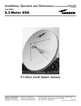
Figure 1 - Typical System
System Components
• UltraSpan™ Antenna/Amplifier
• Power Inserter
• Power Supply
• Connecting Cables (not supplied)
Radio Modem Adapter Cable
Antenna/LNA Feeder Cable
The Power Inserter combines the RF signal from the Radio Modem (not shown)
with the 7.5 VDC power from the Power Supply.
The combined DC power and RF signal are fed to the Antenna/Amplifier using
coaxial cable (not included).
The Antenna/Amplifier mounts to a mast using the included mounting bracket.
Typical System

Installation Instructions
The installation, maintenance, or removal of antenna systems requires qualified, experi-
enced personnel. Andrew installation instructions have been written for such personnel.
Antenna systems should be inspected once a year by qualified personnel to verify proper
installation, maintenance, and condition of equipment.
FCC exposure limits require minimum separation of 2 m between the user and the
radiating elements.
Andrew disclaims any liability or responsibility for the results of improper or unsafe instal-
lation practices.
Notice:
Mount Antenna
1
Select Antenna Polarization. Use antenna polarity indicator on back
cover (see Figure 2). Rotate antenna 90° to change polarity.
Antenna Polarity Indicator
(shown Horizontal polarity)
Rotate Antenna 90 degrees
Counterclockwise for Vertical Polarity
Antenna RF Connector
Type 'N' Female model QD-24-0010
(50 Ohm Shown)
Type 'F' Female model QD-24-0040
(75 Ohm)
Standard
Mounting Bracket
Figure 2 - Back Cover Details
2
Assemble Mast Clamp (Figure 3) to Mast Bracket. Slide mast clamp
legs into slot on mast bracket (Figure 4), then slide up to top of the slot
(Figure 5).
Figure 3 - Mast
Clamp
Figure 4 (Antenna
Removed for Clarity)
Figure 5 (Antenna
Removed for Clarity)
5
3
Mount to Mast (Figure 6).
Slide unit with mast clamp
over suitable mast (up to 2 inch-
es) and secure with included L
Bolt.
Figure 6 - Unit
Mounted to Mast

DC Power Inserter
Connections,
Indicators, and Labels
The Power Inserter injects DC power into the RF cable. The power is carried to
the amplifier with the RF signal via the Antenna Coax.
CAUTION:
Improperly connected cables may cause damage to the power inserter,
radio modem, or another device in line between the power inserter and the
radio modem.
6
Antenna Connections
4
Connect Antenna Coax
to Power Inserter
(Figure 7). Use coaxial cable
equipped with two N male con-
nectors (for 50-ohm models) or
two F male connectors (for 75-
ohm models). Cable and con-
nectors are not supplied.
Figure 7 - Antenna
RF Connection
Installation Instructions (Cont'd.)
5
"To Radio" Connection (Figure 8). N female. Install Radio Modem
Adapter Cable (not supplied) to connect the DC power inserter with the
radio modem.
6
"To Amplifier" Connection (Figure 8). N female (50 ohm cable) or F
female (75 ohm cable). Install Antenna/Amplifier Coaxial Cable (not sup-
plied). The cable options are a 50-ohm cable with Type N male connectors or a
75-ohm cable with Type F male connectors, depending on the model chosen.
Figure 8 - DC Power Inserter Coax Connections
Connect Antenna Coax
(not supplied) to Power
Inserter connector marked
'To Amplifier'
Power Supply
Radio Modem
Adapter Cable
(not supplied)
Connect Radio Modem Adapter
(not supplied) to DC Power
Inserter connector marked
'To Radio'
DC Power Inserter

7
7
DC Power Supply (Figure 9). Install the Power Supply and connect its
cord to the Power Inserter. The power supply provided with the unit is a
universal type, 110/220 VAC to 7.5 VDC converter. The Green LED on the
Power Inserter indicates that dc power is on.
8
Antenna Signal Alignment. Direct the front of the antenna towards the
desired signal and verify signal level. Elevation adjustment of the anten-
na may be necessary depending on proximity to system headend.
9
Waterproof the Antenna Connector. Once the unit is installed and test-
ed, waterproof the antenna connector.
Green LED illuminates when
power is applied
Power Supply
Connect Power Supply
to Power Inserter
Figure 9 - DC Power Inserter Power Connection
Operating Instructions
The unit operates automatically and no user adjustments are required.
The amplifier is designed for 2.4 GHz radios using Time Division Duplex (TDD)
mode of operation. It is equipped with a high speed Tx/Rx switch that detects
transmit signal and switches to transmit mode within 600 nano-seconds. In the
absence of any transmit signal, the unit stays in receive mode. The amplifier
cannot be used with a radio device that uses separate bands for transmit and
receive in a true full duplex mode.

Specifications
General
Frequency Band 2400 - 2500 MHz
Operating Mode Bi-directional TDD
Maximum Transmit Output Power +26.2 dBm (420 mW)
Transmit Input Power 0 dBm min, 23 dBm max
Transmit Gain Automatically adjusts up to 23 dB
Antenna Gain 16 dBi ± 1 dB
Receive Gain 14 dB
Frequency Flatness ±1.0 dB
Noise Figure 3.5 dB
Lightning Protection Ground connection at antenna port
DC Surge Protection At 7.5 VDC input
Operating Temperature -40°C to + 70°C
Power Supply 7.5 VDC at 0.7 amp
RF Connector Type N, Female or Type F, Female
Dimensions 10.75" x 11"
Weight with Standard Mounting Kit 2.2 lb
Transmit Power Gain at 2.45 GHz and 25°C
Input Level, at amplifier Typical Output Level
1 mW (0 dBm) 250 mW
1.3 mW (1 dBm) 280 mW
1.6 mW (2 dBm) 330 mW
2 mW (3 dBm) 380 mW
2.5 mW (4 dBm) 420 mW
50 mW (17 dBm) 420 mW
100 mW (20 dBm) 420 mW
200 mW (23 dBm) 420 mW
Above 2.5 mW input, the amplifier attenuates the input signal power and main-
tains the output power typically at 420 mW.
Do not exceed 200 mW (+23 dBm) of input power to the amplifier.
CAUTION:
Andrew Corporation
10500 West 153rd Street
Orland Park, IL U.S.A. 60462
Telephone: 708/349-3300
FAX (U.S.A.): 1-800-349-5444
Internet: http:/www.andrew.com
Customer Service, 24 hours: U.S.A. • Canada • Mexico: 1-800/255-1479
U.K.: 0800 250055
Other Europe: +44 1592 782612
Printed in U.S.A. 12/01
Copyright © 2001 by Andrew Corporation
Functional Block Diagram
/