Page is loading ...

27 February, 2001
USERS GUIDE
for the
SELECTAMP CDMA 800 CHANNELIZED AMPLIFIER
MANUAL NO. AE04B-A0279
REVISION --
The information set forth in this document and all rights in and to inventions
disclosed herein, and patents which might be granted thereon disclosing,
employing or covering the materials, methods, techniques or apparatus
described herein are the exclusive property of Andrew Corporation.
This document is an operation and maintenance manual. No disclosure or
reproduction of the information or drawings shall be made of any other
purpose without the prior written consent of Andrew. Use of the information
contained herein to fabricate or assemble any item in whole or in part is
expressly prohibited.
These goods are subject to U.S. Department of State, International Traffic
in Arms Regulations, 22 CFR 120-130.
This transmitter is intended for use at fixed base station sites only, and is
not to be marketed for mobile use. As such, under Section 1.1307 of the
FCC Rules, the transmitter is not currently subject to the Commission’s
environmental rules pertaining to the routine evaluation for RF exposure
prior to equipment authorization.
2601 Telecom Parkway Richardson, Texas 75082-3521
Phone: 972-952-9700 Fax: 972-952-0019

AE04B-A0279 Rev. -- LIST OF EFFECTIVE PAGES
Document use is restricted to that described on cover i
LIST OF EFFECTIVE PAGES
Dates of issue for original and changed pages are:
Original................... O.................21 June 2000
TOTAL NUMBER OF PAGES IN THIS PUBLICATION IS __,
CONSISTING OF THE FOLLOWING:
Page
Change No.
(O = Original Page)
Title Page
O
List of Effective Pages (i)
O
Safety Summary (ii)
O
Table of Contents (iii - iv)
O
Chapter 1 (1-1 thru 1-5)
O
Chapter 2 (2-1)
O
Chapter 3 (3-1 thru 3-3)
O
Chapter 4 (4-1)
O
Appendix A (A-1 thru A-5)
O
Appendix B (B-1 thru B-15)
O
Appendix C (C-1 thru C-15)
O
Appendix D (D-1 thru D-2)
O

AE04B-A0279 Rev. -- SAFETY SUMMARY
Document use is restricted to that described on cover ii
SAFETY SUMMARY
High voltage is used in the operation of this
equipment. Death on contact may result if
personnel fail to observe the following
safety precautions:
Do not be misled by the term "Low Voltage." Potentials as low as 50 volts may cause death under
adverse conditions.
Do not crush, puncture, disassemble, or otherwise mutilate batteries. Leaking batteries can cause
serious damage to equipment and injury to personnel.
Do not remove covers or access plates on the equipment unless you are authorized to do so.
Do not work on electronic equipment unless there is another person nearby who is familiar with the
operation of the equipment and is trained in administering first aid.
Whenever possible, disconnect the equipment from the power source before beginning maintenance.
To prevent electrical shock or damage to the equipment, do not operate it until you thoroughly
understand the operation and function of all controls, indicators, and connectors.
Turn off all power to the equipment before replacing any fuses.
FIRST AID
In case of electrical shock:
Do not try to pull or grab the individual.
If possible, turn off the electrical power.
If you cannot turn off the electrical power, pull, push, or lift the person to safety using a dry wooden pole,
a dry rope, or some other insulating material.
Send for help as soon as possible.
After the injured person is no longer in contact with the source of electrical shock, move the person a
short distance away and immediately administer first aid and artificial resuscitation as required.

AE04B-A0279 Rev. -- TABLE OF CONTENTS
Document use is restricted to that described on cover iii
TABLE OF CONTENTS
CHAPTER 1 DESCRIPTION.............................................................................................................. 1-1
1.1 OVERVIEW............................................................................................................................. 1-1
1.2 ELECTRICAL SPECIFICATIONS............................................................................................. 1-1
1.3 MECHANICAL SPECIFICATIONS............................................................................................ 1-2
1.4 ENVIRONMENTAL SPECIFICATIONS .................................................................................... 1-2
1.5 TECHNICAL ASSISTANCE .................................................................................................... 1-2
CHAPTER 2 OPERATIONAL OVERVIEW......................................................................................... 2-1
2.1 OVERVIEW............................................................................................................................. 2-1
2.2 RF DISTRIBUTION.................................................................................................................. 2-1
2.3 POWER DISTRIBUTION ......................................................................................................... 2-1
2.4 CONTROL DISTRIBUTION...................................................................................................... 2-1
CHAPTER 3 FUNCTIONAL DESCRIPTION....................................................................................... 3-1
3.1 OVERVIEW............................................................................................................................. 3-1
3.2 FUNCTIONAL DESCRIPTION ................................................................................................. 3-1
3.2.1 Diplexer........................................................................................................................ 3-1
3.2.2 LNA/Attenuator ............................................................................................................ 3-1
3.2.3 Channelizer.................................................................................................................. 3-1
3.2.3.1 Downconverter................................................................................................ 3-1
3.2.3.2 Upconverter..................................................................................................... 3-2
3.2.3.3 Synthesizer ..................................................................................................... 3-2
3.2.4 Power Supply............................................................................................................... 3-3
3.2.5 Power Amplifier Module ............................................................................................... 3-3
3.2.6 Interconnect Board....................................................................................................... 3-3
3.2.7 Battery Back Up Option ............................................................................................... 3-3
3.2.8 Mounting Kit Options.................................................................................................... 3-3
3.3 PROGRAMMING..................................................................................................................... 3-4
CHAPTER 4 MAINTENANCE ............................................................................................................. 4-1
4.1 MAINTENANCE PROCEDURES ............................................................................................. 4-1
APPENDIX A AMPLIFIER INSTALLATION.........................................................................................A-1
APPENDIX B SOFTWARE INSTALLATION .......................................................................................B-1
APPENDIX C APPLICATION NOTES.................................................................................................C-1
APPENDIX D BATTERY BACK-UP OPTION......................................................................................D-1
LIST OF FIGURES
Figure 1-1 SelectAmp CDMA800 Series Outline Drawing................................................................... 1-3
Figure 1-2 Connector Configuration.................................................................................................... 1-4
Figure 3-1 Isometric View................................................................................................................... 3-2

AE04B-A0279 Rev. -- TABLE OF CONTENTS
Document use is restricted to that described on cover 1
LIST OF TABLES
Table 1-1 Electrical Specifications ..................................................................................................... 1-1
Table 1-2 Mechanical Specifications .................................................................................................. 1-2
Table 1-3 Environmental Specifications.............................................................................................. 1-2

AE04B-A0279 Rev -- DESCRIPTION
Document use is restricted to that described on cover
1-1
CHAPTER 1
DESCRIPTION
1.1 OVERVIEW
The SelectAmp CDMA 800 bi-directional channelized amplifier provides selective frequency amplification of
user specified frequencies in the SMR, Cellular, and ESMR bands. This unit will selectively filter for one 1.25
MHz or 5 MHz channel, depending on the part number ordered, in the Uplink and Downlink band as
determined by the operator. Frequency selection, gain adjustment and fault monitoring is accomplished with
monitor and control circuitry and firmware.
Within this manual, Uplink refers to the RF signal path from the mobile unit to the base station (Donor Cell)
and the Downlink refers to the RF signal path from the base station to the mobile unit.
1.2 ELECTRICAL SPECIFICATIONS
Table 1-1 below contains the electrical specifications for the Channel Selective Amplifier.
Table 1-1 Electrical Specifications
Parameters
Specification
Frequency Range
800 MHz Cellular
Uplink Downlink
824 – 849 MHz 869-894 MHz
Power
Three wire, 90 to 260 VAC @ 200 watts.
SAW Filter 3 dB Bandwidth
1.5 MHz or 5 MHz.
Noise Figure
5 dB maximum.
RF Port Impedance
50 ohms nominal.
Maximum Input Signal Without damage
+10 dBm with no attenuation.
CDMA Power Output
8 Watts Downlink, 1Watt Uplink.
Spurious Emissions per J-STD-008
(Measured from filter center frequency).
-45 dBc min @ 885 KHz.
-13 dBm max @ 1.25 MHz.
-45 dBm min @ 1.25 MHz.
In-Band Spurious
-30 dBm or better at maximum gain.
Status
Frequency setting, gain setting, and module failure via
phone interface.
Power Gain
Downlink
Uplink
65 to 95 dB, adjustable in 2 dB steps.
55 to 85 dB, adjustable in 2 dB steps.

AE04B-A0279 Rev -- DESCRIPTION
Document use is restricted to that described on cover
1-2
1.3 MECHANICAL SPECIFICATIONS
Table 1-2 below contains the mechanical specifications for the Amplifier.
Table 1-2 Mechanical Specifications
Parameters
Specification
Size
Amplifier:
Height: 41 cm (16.3 inches).
Width: 31 cm (12 inches).
Depth: 31 cm (12 inches).
(Excluding heatsinks, connectors, handles, and feet.)
Weight
Amplifier: 45 lbs (21 kg).
Mounting
Four holes spaced (295 x 371 mm) (11.6 x 14.62 inches).
Hole diameter = 0.453 inches.
Power Connections
Weather proof 3 Pin Male (AC), 3 Pin Female (DC)
RF Connections
Type N female.
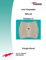
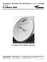
Figures 1-1 and 1-2 show outline mounting and connector locations for the SelectAmp series amplifiers. The
Diversity connection is not available on the 2 Watt repeater (CDMA 800-1).
1.4 ENVIRONMENTAL SPECIFICATIONS
Table 1-3 below contains the environmental specifications for the Amplifier.
Table 1-3 Environmental Specifications
Parameters
Specification
Temperature Range (Operating)
Operating: -40 to +60ºC (Vertically mounted with unobstructed
airflow.)
Storage: -40º to +70ºC.
Humidity Range (Operating)
Up to 90 percent non-condensing.
Environmental Protection
NEMA type 4 (IP 66).
1.5 TECHNICAL ASSISTANCE
Technical assistance on this or any other Andrew product is available 24 hours per day through:
Andrew Customer Service
Telephone: 1-800-255-1479
Fax: 1-708-349-5444

AE04B-A0279 Rev -- DESCRIPTION
Document use is restricted to that described on cover
1-3

AE04B-A0279 Rev -- DESCRIPTION
Document use is restricted to that described on cover
1-4
Figure 1-1 SelectAmpCDMA 800 Series Outline Drawing

AE04B-A0279 Rev -- DESCRIPTION
Document use is restricted to that described on cover
1-5
RF PORT
(TOWARDS MOBILE)
POWER FUSE GLAND FOR REMOTE
STATUS CABLE
RF PORT
(TOWARDS BASE STATION)
RF PORT
(TOWARDS DIVERSITY
ANTENNA)
AC POWER INLET
GROUND
LINE
NEUTRAL
DC POWER INLET
(BATTERY BACK-UP)
+V
HEALTH
GROUND
GROUND LUG
Figure 1-2 SelectAmpCDMA 800 Series Connector Configuration

AE04B-A0279 Rev -- OVERVIEW
Document use is restricted to that described on cover 2-1
CHAPTER 2
OPERATIONAL OVERVIEW
2.1 OVERVIEW
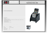
Refer to Figure 2-1. The SelectAmp CDMA 800 bi-directional channelized amplifier provides selective
frequency amplification of user specified frequencies in the SMR, Cellular, and ESMR bands. This unit will
selectively filter for one 1.25 MHz or 5 MHz channel, depending on the part number ordered, in the Uplink
and Downlink band as determined by the operator. This is accomplished by downconverting the desired
signals to a 70 MHz intermediate frequency and using narrowband SAW filters to provide adjacent channel
rejection
2.2 RF DISTRIBUTION
The amplifier contains two paths; forward, or downlink, from the base station to the mobile, and reverse, or
uplink, from the mobile to the base station. Each path includes a diplexer, low noise amplifier, channelizer,
and power amplifier. The diplexers and channelizers determine the frequencies to be amplified.
2.3 POWER DISTRIBUTION
Main power for the amplifier is provided by a 14 amp power supply operating at +15 VDC. The power supply
accepts 90 - 260 VAC inputs. The interconnect board distributes +15 volts, +5 volts, and -5 volts to the
various modules.
2.4 CONTROL DISTRIBUTION
The operator has control over the gain and operating frequency of each path. Computer inputs for gain and
channel settings are routed to each low noise amplifier and channelizer. The gain setting is a four bit word
that sets downlink gain from 65 dB to 95 dB, and uplink gain from 55 to 85 dB. The channel setting is a
three wire serial input to a synthesizer in each channelizer. Each module outputs a status message to
indicate the overall condition of the active devices. If an active device fails, the module reports a fault.

AE04B-A0279 Rev -- OVERVIEW
Document use is restricted to that described on cover 2-2
LNA/
ATTENUATOR
LNA/
ATTENUATOR
CHANNELIZER
CHANNELIZER
5 WATT
POWER AMP
10 WATT
POWER AMP
POWER SUPPLY INTERCONNECT BOARD
POWER/
CONTROL BUS
POWER/
CONTROL BUS
DOWNLINK
FILTER
UPLINK FILTER
DOWNLINK
FILTER
UPLINK FILTER
DIPLEXER
DIPLEXER
TO
ANTENNA
TO
ANTENNA
FIGURE 2-1
BLOCK DIAGRAM, SELECTAMP CDMA 800 REPEATER

AE04B-A0279 Rev -- FUNCTIONAL DESCRIPTION
Document use is restricted to that described on cover 3-1
CHAPTER 3
FUNCTIONAL DESCRIPTION
3.1 OVERVIEW
The SelectAmp CDMA 800 bi-directional channelized amplifier provides selective frequency amplification of
user specified frequencies in the SMR, Cellular, and ESMR bands. This unit will selectively filter for one 1.25
MHz or 5 MHz channel, depending on the part number ordered, in the Uplink and Downlink band as
determined by the operator. This is accomplished by downconverting the desired signals to a 70 MHz IF
and using narrowband SAW filters to provide adjacent channel rejection.
3.2 FUNCTIONAL DESCRIPTION
Refer to Figure 3-1. Each path in the SelectAmp consists of four major modules: diplexers, LNA/attenuator,
channelizer, and power amplifier. These four modules are powered by, interconnected by, and monitored by
the power supply, interconnect board, and the status and control module respectively. Diplexing of the
uplink and downlink signals is accomplished by diplexer filters tuned to the required band (SMR, Cellular, or
ESMR). This view shows a third LNA/Attenuator for the diversity option.
These modules perform the function of selecting one 1.25 or 5 MHz channel out of the SMR, Cellular, or
ESMR band for amplification.
3.2.1 Diplexer
The diplexer module consists of dual filters with a common port on one end and two separate ports on the
other. One side of the diplexer is tuned for the uplink band, the other side for the downlink band. Insertion
loss of each filter is 2 dB maximum and 65 dB minimum rejection to the opposite band.
3.2.2 LNA/Attenuator
The LNA/attenuator module contains gain stages and digitally controlled attenuators. The gain of this
module is adjustable to permit the overall gain of the downlink path to be adjusted between 65 and 95 dB,
and the uplink path to be adjusted between 55 and 85 dB.
3.2.3 Channelizer
The channelizer module contains three boards shielded by aluminum dividers. These three boards, which
are described below, provide the channel selectivity for the SelectAmp. Overall gain of the Channelizer
module is 5 dB.
3.2.3.1 Downconverter
The downconverter board consists of a mixer driven by a synthesizer, and gain stages. The DC current draw
of each gain stage is monitored by a window comparator for status. The window comparator will indicate a
fault, if the gain stage has an open or short failure. The output of the down converter is fed to the
upconverter board.

AE04B-A0279 Rev -- FUNCTIONAL DESCRIPTION
Document use is restricted to that described on cover 3-2
3.2.3.2 Upconverter
The upconverter board mixes the filtered 70 MHz IF with a signal from the synthesizer and outputs the same
frequency that was input to the downconverter. The upconverter consists of a SAW filter centered at 70
MHz with a 1.5 MHz or 5 MHz 3 dB bandwidth, depending on the part number ordered, a mixer and gain
stages. The DC current draw of each gain stage is monitored by a window comparator. The window
comparator indicates a fault, if the gain stage has an open or short condition.
LNA/
ATTENUATOR
LNA/
ATTENUATOR
CHANNELIZER
CHANNELIZER
5 WATT
POWER AMP
10 WATT
POWER AMP
POWER SUPPLY INTERCONNECT BOARD
POWER/
CONTROL BUS
POWER/
CONTROL BUS
DOWNLINK
FILTER
UPLINK FILTER
DOWNLINK
FILTER
UPLINK FILTER
DIPLEXER
DIPLEXER
TO
ANTENNA
TO
ANTENNA
Figure 3-1 SelectAmp800 Block Diagram

AE04B-A0279 Rev -- FUNCTIONAL DESCRIPTION
Document use is restricted to that described on cover 3-3
3.2.3.3 Synthesizer
The synthesizer board consists of a synthesizer circuit that is driven by a reference oscillator and distribution
amplifiers. The synthesizer operating frequency is programmed from the status and control module. The
uplink and downlink frequencies are set with a computer that has Andrew designed frequency control
software installed on it. This software is a Microsoft® Windows™ application that allows the operator to
input the desired RF frequency and gain setting.
The status and control module converts the operator's input to the appropriate frequency command for the
synthesizer. The output of the synthesizer is split to the downconverter mixer and upconverter mixer.
3.2.4 Power Supply
The power supply assembly consists of an in-line EMI filter, switching power supply, and interface cable.
The power supply accepts a 90 to 264 VAC input and outputs +15 VDC for use by the rest of the amplifier.
Power is distributed to the active modules through the interconnect board.
3.2.5 Power Amplifier Modules
The downlink power amplifier module provides 45 dB of final gain and is J-STD-008 compliant up to 10
Watts output. The uplink power amplifer module has 27 dB of gain and is J-STD-008 compliant up to 1
Watt output. A thermal sensor mounted on the heatsink monitors the total heat dissipation of the power
amplifers.
3.2.6 Interconnect Board
The interconnect board distributes power to the other modules, and provides status information and control
capabilities at the local and remote connections. Control functions include synthesizer channel selection and
individual channel attenuation settings. Status information includes module summary status for the
LNA/attenuators, channelizers, power amplifiers and battery backup.
3.2.7 Battery Back Up Option
The battery back up (BBU) provides emergency operating power in case of AC power loss. Under normal
conditions, the BBU is charged by an internal charger. If AC power loss occurs, the BBU automatically
comes on-line and this condition is reported to the status and control module. The BBU has been sized for
back up capability over the full –40º to +60ºC tempe rature range and will power the repeater for
approximately two hours when ambient temperature is –40ºC. Actual back up time will increase with
warmer temperatures.
3.2.8 Mounting Kit Options
A mounting kit (EENCL-90004) is available for ease of installation on walls or poles. Refer to Appendix A
for installation instructions.

AE04B-A0279 Rev -- FUNCTIONAL DESCRIPTION
Document use is restricted to that described on cover 3-4
3.3 PROGRAMMING
The amplifier and channel number are set by connecting a laptop computer with the supplied cable and
adapter to the RJ-45 (see Figure 1-2) port. Remote access is available by wireline connection to the RJ-11
port. To set a specific channel number or gain, refer to Appendix B.
The software enclosed with this unit is designed to provide local or remote control capability for one
repeater. A more sophisticated software package is available for monitor and control of a repeater network.
Contact customer assistance at the phone number indicated in Chapter 1 for more information.

AE04-A0279 Rev -- MAINTENANCE
Document use is restricted to that described on cover 4-1
CHAPTER 4
MAINTENANCE
4.1 MAINTENANCE PROCEDURES
The SelectAmp contains no user-serviceable parts. To verify operation, check the amplifier against the
electrical specifications provided in Chapter 1. If the amplifier does not meet these specifications, call 972-
952-9894 Monday through Friday, between 8:00 a.m. and 5:00 p.m. CST, for instructions regarding return of
the defective unit for repair.

AE04B-A0279 Rev -- APPENDIXA: AMPLIFIER INSTALLATION
Document use is restricted to that described on cover
A-1
APPENDIX A
AMPLIFIER INSTALLATION
1. List of Material
• Qty 1 – SELECTAMP800 Amplifier
• Qty 1 - User Guide (AE02B-AXXXX)
• Qty 1 - Programming Cable (ECATL-80700)
• Qty 1 - Adapter, RJ45 to DB9 (AE02M-D0419-001)
• Qty 1 - Adapter, RJ45 to DB25 (AE02M-D0420-001)
• Qty 1 - Power Cable, 12 ft. (AE02C-D3300-001)
• Qty 1 - Diskette containing SMARTpc Lite software for Amplifier Control
(AE02R-AXXXX-XXX)
2. Tools Required
• Qty 1 - 3/8 in. Electric Drill
• Qty 1 - 3/8 in. Diameter Drill Bit
• Qty 1 - 3/8 in. Diameter Masonry Drill Bit
• Qty 1 - No. 2 Phillips Screw Driver
• Qty 1 - No. 2 Flat Head Screw Driver
• Qty 1 - 9/16 Wrench
• Qty 1 - Pair of Medium Wire Cutters
• Qty 1 - Laptop Computer
• Qty 1 - Amplifier Mounting Kit (EENCL-90004)
3. Determine Location for Amplifier
1. Determine if the amplifier will be mounted on a wall or a pole.
2. If amplifier is going to be mounted on a wall, is it concrete or wallboard?
3. If amplifier is going to be mounted on a pole, what is the diameter of the pole? The
Amplifier mounting kit will support a pole up to 12 inches in diameter.
4. Locate the amplifier within 10 feet of a VAC @50/60 Hz Electrical Outlet.

AE04B-A0279 Rev -- APPENDIXA: AMPLIFIER INSTALLATION
Document use is restricted to that described on cover
A-2
4. Amplifier Wall Installation, Figure 1.
Figure 1 Wall Mounting
Mounting Unistrut (2)
Floating Nut, 3/8"-16 (4)
Amplifier
Bolt, Hex Hd, 3/8"-16 x .75 (4)
Flat Washer, 3/8" (4)
Mounting Feet (4)

AE04B-A0279 Rev -- APPENDIXA: AMPLIFIER INSTALLATION
Document use is restricted to that described on cover
A-3
1. Location found
2. Install the amplifier to the wall using mounting kit
3. Material used from mounting kit for wall installation.
• Channel (Qty - 2ea)
• Clamp Nut (Qty - 4ea)
• 3/8”-16 X .75 Hex Head Bolt
• Flat Sealing Washer
4. Materials provided for wall mounting of unistrut.
• Anchors (EAHRS-00002) (Qty – 4ea)
• Screw, Pan Head, #10-32 X 1.50 (Qty – 4ea)
• Washer, #10 (Qty- 4ea)
5. Prepare Unistrut
a. Drill two holes (0.219 inches in diameter) in each mounting unistrut.
b. The holes should be located between the slots and spaced approximately 12
inches apart, centered in the unistrut.
c. Prepare Holes in wall.
d. Mark hole locations from modified mounting unistrut.
e. Unistruts should be spaced 11.60 inches apart (center to center)
f. For wallboard approximately 5/8 in. thick.
• Drill 3/8 in. diameter holes
• Depress wing tabs so that anchor will fit into hole
• Push in until flush with wallboard
g. Concrete Installation
• Drill 3/8 diameter hole approximately 1 in. deep
• Depress wing tabs so that anchor will fit into hole
• Push in until flush with outside surface of concrete
h. Mount channels to the Wall
• Line mounting unistruts up with the holes drilled in the wall
• Use #10 hardware to install
i. Install amplifier to Channels
• Install the clamp nuts from the mounting kit into the mounting unistrut.
• Use the 3/8 hardware supplied with the mounting kit to install the amplifier to
the mounting unistrut.
/