Page is loading ...

mini Repeater
MRx18
Release 2
Single-Band
User's Manual
M0139ADD

User’s Manual for
MRx18 Rel. 2 Single-Band
Page 2 M0139ADD.doc
© Copyright 2009 CommScope, Inc.
All rights reserved.
Andrew Solutions is a trademark of CommScope, Inc.
All information contained in this manual has been revised thoroughly. Yet Andrew
Solutions accepts no liability for any omissions or faults.
Andrew Solutions reserves the right to change all hard- and software characteristics
without notice.
Names of products mentioned herein are used for identification purposes only and may
be trademarks and / or registered trademarks of their respective companies.
No parts of this publication may be reproduced, stored in a retrieval system, transmitted
in any form or by any means, electronical, mechanical photocopying, recording or
otherwise, without prior written permission of the publisher.
Andrew Wireless Systems GmbH, 09-September-2009

Page 3
TABLE OF CONTENTS
1. GENERAL 7
1.1. USED ABBREVIATIONS 7
1.2. HEALTH AND SAFETY WARNINGS 8
1.3. ABOUT ANDREW SOLUTIONS 9
1.4. INTERNATIONAL CONTACT ADDRESSES FOR WIG CUSTOMER SUPPORT 10
2. INTRODUCTION 13
2.1. PURPOSE 13
2.2. THE MRX18 13
3. FUNCTIONAL DESCRIPTION 15
3.1. GENERAL 15
3.2. DESIGN AND CONNECTORS 16
4. INSTALLATION AND COMISSIONING 17
4.1. MECHANICAL INSTALLATION 17
4.2. ELECTRICAL INSTALLATION 18
5. SOFTWARE SETUP 21
5.1. LOGIN 21
5.2. MENU BAR - BUTTONS 23
5.3. STATUS BAR 23
5.4. STATUS 24
5.5. SETTINGS 26
5.5.1. Settings - Radio Frequency 27
5.5.2. Settings - Alarms 30
5.5.3. Settings – Modem Control 31
5.5.4. Settings – LAN Connectivity 33
5.5.5. Settings – User Account 36
5.6. MAINTENANCE 37
5.7. LOGOUT 39

User’s Manual for
MRx18 Rel. 2 Single-Band
Page 4 M0139ADD.doc
5.8. UPLOAD NEW SOFTWARE VERSION 40
6. OPTIONAL EQUIPMENT 41
6.1. EXTERNAL MODEM (KIT) 41
6.2. ANTENNA 41
6.3. ADAPTER CABLE 41
7. ALARMING AND SUPERVISION 43
7.1. ALARM LEDS 43
7.2. DISPLAY AND RESET & INSTALLATION ASSISTANCE BUTTON 44
8. SPECIFICATIONS 47
8.1. ELECTRICAL SPECIFICATIONS MRX18 47
8.2. ENVIRONMENTAL AND SAFETY SPECIFICATIONS MRX18 51
8.3. MECHANICAL SPECIFICATIONS MRX18 51
9. SPARE PARTS LIST 52
10. INDEX 53
11. LIST OF CHANGES 55

Page 5
FIGURES AND TABLES
figure 3-1 Block diagram................................................................................................15
figure 3-2 Connectors of MRx18....................................................................................16
figure 4-1 MRx18, position of screws for wall mounting.................................................17
figure 4-2 Power connection of DC connector with MRx18............................................18
figure 5-1 Login, correct.................................................................................................21
figure 5-2 Login, incorrect..............................................................................................22
figure 5-3 Status – General & Alarms, exemplary..........................................................24
figure 5-4 Status – General & Alarms, high-contrast page.............................................24
figure 5-5 Settings – Radio Frequency, exemplary........................................................27
figure 5-6 Settings - Radio Frequency, high-contrast page ...........................................27
figure 5-7 Settings – Alarms ..........................................................................................30
figure 5-8 Settings – Alarms, high-contrast page...........................................................30
figure 5-9 Settings – Modem Control.............................................................................31
figure 5-10 Settings – Modem Control, high-contrast page ...........................................31
figure 5-11 Settings – LAN Connectivity........................................................................33
figure 5-12 Settings– LAN Connectivity, high-contrast page .........................................33
figure 5-13 Settings - User Account...............................................................................36
figure 5-14 Settings – User Account, high-contrast layout.............................................36
figure 5-15 Maintenance................................................................................................37
figure 5-16 Maintenance, high-contrast page ................................................................37
figure 5-17 Logout .........................................................................................................39
figure 5-18 Upload new software version ......................................................................40
figure 6-1 Coverage antenna for MRx18, optional equipment .......................................41
figure 7-1 Display and alarm LEDs, exemplary..............................................................43
figure 7-2 Display with reset button and alarm LEDs , exemplary .................................44
figure 7-3 Display – RSSI ..............................................................................................45
figure 7-4 Display – Gain UL and DL.............................................................................45
figure 7-5 Display – P
out
UL and DL...............................................................................45
figure 8-1 Cabinet drawing MRX18................................................................................51
table 1-1 List of international contact addresses............................................................11
table 5-1 Status bar, description....................................................................................23
table 5-2 Status page ....................................................................................................25
table 5-3 Settings – User Account page........................................................................36
table 5-4 Maintenance page, description.......................................................................39
table 7-1 Alarm LEDs ....................................................................................................44

User’s Manual for
MRx18 Rel. 2 Single-Band
Page 6 M0139ADD.doc
For your notes:

Page 7
1. GENERAL
1.1. USED ABBREVIATIONS
ALC Automatic Level Control
AMPS American Mobile Phone System or Advanced Mobile Phone System
APAC Automatic Power Adjustment Circuit
BCCH Broadcast Control Channel
BITE Built-In Test Equipment
BTS Base Transceiver Station
CDMA Code Division Multiple Access
CEPT Conférénce Européenne des Postes et Télécommunications
CF Center Frequency
CFO Center Frequency Offset
DL Downlink
EDGE Enhanced Data Rates for GSM Evolution
ESD Electrostatic Discharge
ETACS Enhanced TACS
ETS European Telecommunication Standard
ETSI European Telecommunication Standards Institute
FSK Frequency Shift Keying
GSM Global System for Mobile Communication
I
2
C-Bus Inter-Integrated Circuit Bus (Philips)
ID No Identification Number
IF Intermediate Frequency
LMT Local Maintenance Terminal
MOR Microwave Optical Repeater
MR Microwave Repeater
MS Mobile Station
OMC Operation and Maintenance Center
PCMCIA Personal Computer Modem Communication International Association
PCS Personal Communication System
PSTN Public Switched Telephone Network
Rev Revision
RF Radio Frequency
RLP Radio Link Protocol
RSSI Receive Signal Strength Indication
RTC Real-Time Clock
RX Receiver
SCL Serial Clock
SDA Serial Data
TACS Total Access Communication System
TCH Traffic Channel
TDMA Time Division Multiple Access
TX Transmitter
UE User Equipment
UL Uplink
UMTS Universal Mobile Telecommunication System
UPS Uninterruptable Power Supply
VSWR Voltage Standing Wave Ratio
WIG Wireless Innovations Group

User’s Manual for
MRx18 Rel. 2 Single-Band
Page 8 M0139ADD.doc
1.2. HEALTH AND SAFETY WARNINGS
1. Only suitably qualified personnel is allowed to work on this unit and only after becoming
familiar with all safety notices, installation, operation and maintenance procedures
contained in this manual.
2. Read and obey all the warning labels attached to the unit. Make sure that the warning
labels are kept in a legible condition and replace any missing or damaged labels.
3. Obey all general and regional installation and safety regulations relating to work on high
voltage installations, as well as regulations covering correct use of tools and personal
protective equipment.
4. Keep operating instructions within easy reach and make them available to all users.
5. It is the responsibility of the network provider to implement prevention measures to avoid
health hazards which may be associated to radiation from the antenna(s) connected to
the unit.
6. The antennas of the repeater (integrated and / or external) have to be installed in a way
that the regional and national RF exposure compliance requirements are met.
7. Make sure access is restricted to qualified personnel.
8. Only licence holders for the respective frequency range are allowed to operate this unit.
9. Use this equipment only for the purpose specified by the manufacturer. Do not carry out
any modifications or fit any spare parts which are not sold or recommended by the
manufacturer. This could cause fires, electric shock or other injuries.
10. Before opening the unit, disconnect mains.
11. ESD precautions must be observed! Before commencing maintenance work, use the
available grounding system to connect ESD protection measures.
12. This unit complies with European standard EN60950.
13. IMPORTANT NOTE: To comply with FCC RF exposure compliance requirements, the
following antenna installation and device operating configurations must be satisfied: A
separation distance of at least 20 cm must be maintained between the antenna of this
device and all persons. RF exposure compliance may need to be addressed at the time
of licensing, as required by the responsible FCC Bureau(s), including antenna co-location
requirements of 1.1307(b)(3). Maximum permissible antenna gain is 12 dBi.
14. Make sure the repeater settings are according to the intended use (see also product
information of the manufacturer) and regulatory requirements are met.
15. Although the repeater is internally protected against overvoltage, it is strongly
recommended to earth the antenna cables close to the antenna connectors of the
repeater for protection against atmospheric discharge.

Page 9
1.3. ABOUT ANDREW SOLUTIONS
Andrew Wireless Systems GmbH based in Buchdorf/ Germany, is a leading
manufacturer of coverage equipment for mobile radio networks, specializing in low
cost, high performance, RF and optical repeaters. Our optical distributed networks
and RF repeater systems provide coverage for every application: outdoor use, indoor
installations, tunnels, subways and many more.
Andrew Wireless Systems GmbH belongs to the Wireless Innovations Group (WIG).
Being a part of Andrew Solutions, WIG has unparalleled experience in providing RF
coverage and capacity solution for wireless networks in both indoor and outdoor
environment.
Andrew Solutions, a CommScope Company, is the foremost supplier of one-stop,
end-to-end radio frequency (RF) solutions. Our products are complete solutions for
wireless infrastructure from top-of-the-tower base station antennas to cable systems
and cabinets, RF site solutions, signal distribution, and network optimization.
Andrew Solutions has global engineering and manufacturing facilities. In addition, it
maintains field engineering offices throughout the world.
We operate a quality management system in compliance with the requirements of
ISO 9001. All equipment is manufactured using highly reliable material. In order to
ensure constant first-rate quality of the products, comprehensive quality monitoring is
conducted at all fabrication stages. Finished products leave the factory only after a
thorough final acceptance test, accompanied by a test certificate guaranteeing
optimal operation.
The declaration of conformity for the product is available upon request from the local
sales offices or from Andrew Solutions directly.
To make the utmost from this unit, we recommend you carefully read the instructions
in this manual and commission the unit only according to these instructions.
For technical assistance and support, contact the local office or Andrew Solutions
directly at one of the following addresses listed in the next chapter.

User’s Manual for
MRx18 Rel. 2 Single-Band
Page 10 M0139ADD.doc
1.4. INTERNATIONAL CONTACT ADDRESSES FOR WIG CUSTOMER
SUPPORT
Wireless Innovations Group (WIG)
Americas:
Canada United States
Andrew Solutions Canada
Andrew Solutions,
Andrew LLC, A CommScope Company
Mail
620 North Greenfield Parkway
Garner, NC 27529
U.S.A.
Mail
620 North Greenfield Parkway
Garner, NC 27529
U.S.A.
Phone
+1-905-878-3457 (Office)
+1 416-721-5058 (Mobile)
Phone
+1-888-297-6433
Fax
+1-905-878-3297
Fax
+1-919-329-8950
E-mail
WIsupport.us@andrew.com
E-mail WIsupport.us@andrew.com
Brazil & South America
Mexico, Central America &
Caribbean region
Andrew Solutions,
A CommScope Company
Andrew Solutions Mexico
Mail
Av. Com. Camilo Julio 1256
Predio B
Zonal Industrial CP 597
Sorocaba SP 18086-000
Brazil
Mail
Monte Elbruz 124-402A
Col. Palmas Polanco 11560
Mexico, D.F.
Mexico
Phone
+ 55-15-9104-7722
Phone
+ 52-55-1346-1900 (Office)
+52-1-55-5419-5260 (Mobile ).
Fax
+ 55-15-2102-4001
Fax
+52-55-1346-1901
E-mail [email protected]
E-mail [email protected]
APAC Countries:
China Australia
Andrew Solutions Hong Kong
Andrew Corporation (Australia)
LLC Pty Ltd.
Mail
Room 915
Chevalier Commercial Centre
8 Wang Hoi Rd
Kowloon Bay SAR
Hong Kong
Mail
Unit 1
153 Barry Road
Campbellfield
VIC 3061
Australia
Phone
+852-310-661-00
Phone
+613-9300-7969
Fax
+852-2751-7800
Fax
+613-9357-9110
E-mail [email protected]
E-mail [email protected]

Page 11
Europe:
United Kingdom France
Andrew Solutions UK Ltd Andrew Solutions France
Mail
Unit 15, Ilex House
Mulberry Business Park
Fishponds Road
Wokingham Berkshire
RG41 2GY
England
Mail
28, Rue Fresnel
Z.A Pariwest
BP 182
78313 Coignières Cedex
France
Phone
+44-1189-366-792
Phone
+33 1 30 05 45 50
Fax
+44-1189-366-773
Fax
+33 1 34 61 13 74
E-mail [email protected]
E-mail [email protected]
Germany Czech Republic
Andrew Wireless Systems GmbH
Andrew Solutions Czech Republic
C-Com, spol. s r.o
Mail
Industriering 10
86675 Buchdorf
Germany
Mail
U Moruší 888
53006 Pardubice
Czech Republic
Phone
+49-9099-69-0
Phone
+420-464-6280-80
Fax
+49-9099-69-930
Fax
+420-464-6280-94
E-mail [email protected]
E-mail [email protected]
Austria Switzerland
Andrew Wireless Systems (Austria)
GmbH
Andrew Wireless Systems AG
Mail
Weglgasse 10
Wien-Schwechat 2320
Austria
Mail
Tiergartenweg 1
CH-4710 Balsthal
Switzerland
Phone
+43-1706-39-99-10
Phone
+41-62-386-1260
Fax
+43-1706-39-99-9
Fax
+41-62-386-1261
E-mail WIsupport.austria@andrew.com
E-mail [email protected]
Italy Spain & Portugal
Andrew Wireless Systems S.r.l., Faenza,
Italy
Andrew Solutions España S.A.
Mail
Via de Crescenzi 40
Faenza 48018
Italy
Mail
C/ Salvatierra, 5 - 3
a
pt.
28034 Madrid
Spain
Phone
+39-0546-697111
Phone
+34-91-745-20 40
Fax
+39-0546-682768
Fax
+34-91-564-29 85
E-mail WIsupport.i[email protected]
E-mail [email protected]
table 1-1 List of international contact addresses

User’s Manual for
MRx18 Rel. 2 Single-Band
Page 12 M0139ADD.doc
For your notes:

Page 13
2. INTRODUCTION
2.1. PURPOSE
The MRx18 is a bi-directional amplifier used to enhance signals between a mobile
and a base station in a mobile network. It has been designed to increase signal
strength in small and medium sized areas such as offices, shops, and basements. By
boosting the signal level the MRx18 increases indoor coverage and allows high data
rate connectivity.
If weak signal transmissions occur within the coverage area due to indoor
applications, topological conditions or distance from the transmitter, a repeater is
used to extend transmission range. In the downlink path, the repeater picks up the
signals from a donor antenna of a BTS / Node B, amplifies and re-transmits it into the
required dark spot. In the uplink path the signal picks up the signals from a
mobile/UE and re-transmits it to the BTS/Node B.
2.2. THE MRx18
Andrew MRx18 gives designers a simple tool to solve their small area coverage and
performance issues.
The MRx18 is easy to install. Also a web-based browser simplifies to commission
and configure the equipment. The RF link (donor) towards the base station is
typically fed from an outdoor antenna while the coverage area is fed by an indoor
antenna. The possibility to adjust the passband of repeater helps to cover any
specific segment or frequency band.
Due to modular design the single varia version MRx18 may be available as a triple-
varia segment or a dual-band-varia version in one cabinet. Auto Gain functionality
enables automatic gain adjustment in order to maximize the performance, however,
gain may be set manually if desired. An alarm interface with a display and LEDs
indicates the status of the equipment locally. Moreover the status and alarms of the
MRx18 can be queried via the web-based browser. The MRx18 has an optional
remote monitor function that provides equipment alarming and basic configuration
settings via a GSM-SMS. Alarm SMSs (including heartbeat) can be sent to the
common Andrew OMC or to any standard SMS receiver (even a mobile phone).
Moreover the MRx18 can be connected to LAN.

User’s Manual for
MRx18 Rel. 2 Single-Band
Page 14 M0139ADD.doc
Easy to install due to light weight, small dimensions, and Auto Gain
functionality
Easy commissioning via web-based browser
Automatic level control (ALC)
Variable bandwidth
LEDs for local alarm indication
Display for RSSI, gain, output power, and status indication
Optional remote control via SMS
Connection to LAN
Remote alarming through SNMP alarm traps
Complying with all regulatory agencies (GSM 05.05, 3GPP and FCC)

Page 15
3. FUNCTIONAL DESCRIPTION
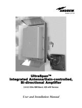
3.1. GENERAL
The MRx18 is a repeater operating in the respective frequency range (e.g. MR918 –
900 MHz frequency range). The operation principle is depicted in the following block
diagram:
E0783B9
figure 3-1 Block diagram

User’s Manual for
MRx18 Rel. 2 Single-Band
Page 16 M0139ADD.doc
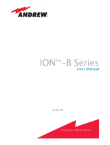
3.2. DESIGN AND CONNECTORS
figure 3-2 Connectors of MRx18
Donor antenna
connector RF BTS
DC connector
Modem connector
DC + Data
Ethernet
Coverage antenna
connector
connector
RF mobile
Reset and
installation assistance
switch
Connector modem RF

Page 17
4. INSTALLATION AND COMISSIONING
4.1. MECHANICAL INSTALLATION
Mount the MRx18 to a wall with two screws.
figure 4-1 MRx18, position of screws for wall mounting
Position of screws

User’s Manual for
MRx18 Rel. 2 Single-Band
Page 18 M0139ADD.doc
4.2. ELECTRICAL INSTALLATION
) Note: The electrical installation has to be performed in accordance with
the safety regulations of the local authorities. Due to safety
reasons, the electrical installation must be performed by qualified
personnel only. The repeater must not be opened.
¾ Connect the antenna cables to the antenna connectors and the antennas.
¾ Use only the power supply delivered with the unit. Do not modify the power
supply unit (PSU) and cable!
Do not mount the PSU to the ceiling!
Connect the DC connector of the power supply and provide mains to the
power supply. Ensure the DC connector is plugged in correctly as in the
following illustrations.
Plug in the male DC connector by
inserting the lug into the guide at
the DC connector with the arrow-
moulded side on top, see
illustrations.
The DC connector of the cable is
equipped with a locking mechanism.
The system of locking the plug is based
on a “push-pull” mechanism. The
locking sleeve has to be pulled back to
free the connection.
figure 4-2 Power connection of DC connector with MRx18
Lug
Locking sleeve
Pull back
locking sleeve
to disconnect!
Guide of DC connector
Lug
Insert lug into guide
Insert with
arrow-moulded
side on top

Page 19
¾ Align the donor antenna towards the BTS. The MRx18 provides an antenna
alignment assistance. Therefore, press the "Reset and installation assistance"
switch (see chapter 3.2 Design and Connectors) for at least four seconds after
(!) the boot process has been finished (i.e. red ALC LED is blinking for four
seconds). This will set the gain to 70 dB and disable Auto Gain for about four
minutes. The status LED will be blinking red/green. Align the donor antenna
towards the BTS/ Node B tower to reach the highest RSSI level possible. Check
the RSSI level at the display (see chapter 7 Alarming and Supervision). After
four minutes, the gain and Auto Gain are adjusted to the same values prior to
the activation of the antenna alignment.
¾ Align the coverage antenna.
As the default settings of the repeater are set to ‘Auto Gain enabled
’, only the
frequencies have to be adjusted. Additionally, the repeater can be customized with a
laptop or PC via Ethernet connector:
¾ For local connection, connect the straight CAT 6 patch cable to the Ethernet
connector of the MRx18 and the network connector of a laptop or PC. For
MRx18 connection to a LAN network, connect the cross-over cable. (Note: The
MRx18 operates at 10 Mbps and full-duplex).
¾ Start a browser (e.g. Internet Explorer 7 or higher, or Mozilla Firefox) and enter
URL: http://192.168.1.1.
) Note: If the connection cannot be established, it might be
necessary to set the IP address of the computer or laptop (Start =>
Settings => Control Panel => Network Connections => Your Network-
Connection => Properties => Internet Protocol (TCP/IP) => Properties =>
Enable ‘Use the following IP address’ and enter an IP address, e.g.
192.168.1.10). Do not use IP addresses 192.168.1.2 or 192.168.1.1!
¾ Enter User name: MRx18 and password: MRx18 (case-sensitive).
¾ Commission the repeater according to the description in the following chapter
and save settings to the repeater.
¾ Disconnect the CAT 6 patch cable and check LEDs and display of the repeater.
In case the Ethernet connection cannot be established due to wrong settings in the
Connectivity page (see chapter 5.5.4 Settings – LAN Connectivity) or if username or
password have been forgotten, these settings can be reset to the default factory
settings.
.
To reset Ethernet settings, username and password to the default factory settings,
press the "Reset and installation assistance switch" during the boot process (i.e. red
ALC LED is blinking for four seconds after power has been supplied) and keep the
switch pressed until the boot process starts again (Ethernet LED starts blinking). It is
not possible to execute a reset when a local connection is established.

User’s Manual for
MRx18 Rel. 2 Single-Band
Page 20 M0139ADD.doc
For your notes:
/