Page is loading ...

Andrew Corporation
10500 West 153rd Street
Orland Park, IL U.S.A. 60462
Telephone: 708-349-3300
FAX (U.S.A.): 1-800-349-5444
Internet: http://www.andrew.com
Customer Service, 24 hours: U.S.A. • Canada • Mexico: 1-800-255-1479
U.K.: 0800 250055 • Republic of Ireland: 1 800 535358
Other Europe: +44 1592 782612
07 November, 2005
Copyright © 2005 by Andrew Corporation
Installation, Operation and Maintenance
Bulletin OM49
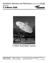
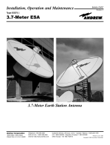
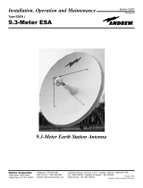
Type ES49( )
4.9-Meter ESA
4.9-Meter Earth Station Antenna
Revision L
Notice
The installation, maintenance, or removal of antenna systems requires qualified, experienced personnel. Andrew installa-
tion instructions have been written for such personnel. Antenna systems should be inspected by qualified personnel to
verify proper installation, maintenance and condition of equipment.
Andrew Corporation disclaims any liability or responsibility for the results of improper or unsafe installation and mainte-
nance practices.
All designs, specifications, and availabilities of products and services presented in this manual are subject to change
without notice.

Introduction
How to Use This Manual
Getting Started
Installation
Procedures
Operation
Preventive
Maintenance
Table of Contents
2
Table of Contents
Introduction. . . . . . . . . . . . . . . . . . . . . . . . . . . . . . . . . . . . . . . . . . . . . . . . . . . . . . . . . . . . . . . . . . . . . . . . 3
Proprietary Data . . . . . . . . . . . . . . . . . . . . . . . . . . . . . . . . . . . . . . . . . . . . . . . . . . . . . . . . . . . . . . . . 4
Information and Assistance. . . . . . . . . . . . . . . . . . . . . . . . . . . . . . . . . . . . . . . . . . . . . . . . . . . . . . . . 4
Notice . . . . . . . . . . . . . . . . . . . . . . . . . . . . . . . . . . . . . . . . . . . . . . . . . . . . . . . . . . . . . . . . . . . . . . . . 4
Technical Assistance . . . . . . . . . . . . . . . . . . . . . . . . . . . . . . . . . . . . . . . . . . . . . . . . . . . . . . . . . . . . 4
Overview . . . . . . . . . . . . . . . . . . . . . . . . . . . . . . . . . . . . . . . . . . . . . . . . . . . . . . . . . . . . . . . . . . . . . . . . . . 5
Content . . . . . . . . . . . . . . . . . . . . . . . . . . . . . . . . . . . . . . . . . . . . . . . . . . . . . . . . . . . . . . . . . . . . . . . 5
Overview . . . . . . . . . . . . . . . . . . . . . . . . . . . . . . . . . . . . . . . . . . . . . . . . . . . . . . . . . . . . . . . . . . . . . . . . . . 6
Warnings . . . . . . . . . . . . . . . . . . . . . . . . . . . . . . . . . . . . . . . . . . . . . . . . . . . . . . . . . . . . . . . . . . . . . . 6
Recommended Tools . . . . . . . . . . . . . . . . . . . . . . . . . . . . . . . . . . . . . . . . . . . . . . . . . . . . . . . . . . . . 7
Parts Verification . . . . . . . . . . . . . . . . . . . . . . . . . . . . . . . . . . . . . . . . . . . . . . . . . . . . . . . . . . . . . . . . 8
Reporting Equipment Loss or Damage . . . . . . . . . . . . . . . . . . . . . . . . . . . . . . . . . . . . . . . . . . . . . . 8
Reporting Visible Loss or Damage. . . . . . . . . . . . . . . . . . . . . . . . . . . . . . . . . . . . . . . . . . . . . . . . . . 8
Reporting Concealed Damage. . . . . . . . . . . . . . . . . . . . . . . . . . . . . . . . . . . . . . . . . . . . . . . . . . . . . . 8
Inventory Equipment Received . . . . . . . . . . . . . . . . . . . . . . . . . . . . . . . . . . . . . . . . . . . . . . . . . . . . 8
Returning Equipment . . . . . . . . . . . . . . . . . . . . . . . . . . . . . . . . . . . . . . . . . . . . . . . . . . . . . . . . . . . . 9
Overview . . . . . . . . . . . . . . . . . . . . . . . . . . . . . . . . . . . . . . . . . . . . . . . . . . . . . . . . . . . . . . . . . . . . . . . . . . 10
Foundation Preparation . . . . . . . . . . . . . . . . . . . . . . . . . . . . . . . . . . . . . . . . . . . . . . . . . . . . . . . . . . 10
Foundation Notes . . . . . . . . . . . . . . . . . . . . . . . . . . . . . . . . . . . . . . . . . . . . . . . . . . . . . . . . . . . . . . . 12
A325 Tensioning . . . . . . . . . . . . . . . . . . . . . . . . . . . . . . . . . . . . . . . . . . . . . . . . . . . . . . . . . . . . . . . 13
Reflector/Backstructure Assembly . . . . . . . . . . . . . . . . . . . . . . . . . . . . . . . . . . . . . . . . . . . . . . . . . .14
Subreflector Support Brackets . . . . . . . . . . . . . . . . . . . . . . . . . . . . . . . . . . . . . . . . . . . . . . . . . . . . .18
Rotating Tube Assembly . . . . . . . . . . . . . . . . . . . . . . . . . . . . . . . . . . . . . . . . . . . . . . . . . . . . . . . . . 20
Polarization Drive Installation . . . . . . . . . . . . . . . . . . . . . . . . . . . . . . . . . . . . . . . . . . . . . . . . . . . . . 21
Subreflector Assembly . . . . . . . . . . . . . . . . . . . . . . . . . . . . . . . . . . . . . . . . . . . . . . . . . . . . . . . . . . . 22
Pedestal Ground Mount Assembly . . . . . . . . . . . . . . . . . . . . . . . . . . . . . . . . . . . . . . . . . . . . . . . . . .24
Pedestal Installation. . . . . . . . . . . . . . . . . . . . . . . . . . . . . . . . . . . . . . . . . . . . . . . . . . . . . . . . . . . . . 24
Reflector to Ground Mount Assembly. . . . . . . . . . . . . . . . . . . . . . . . . . . . . . . . . . . . . . . . . . . . . . . .28
Subreflector Installation and Adjustment . . . . . . . . . . . . . . . . . . . . . . . . . . . . . . . . . . . . . . . . . . . . 30
Overview . . . . . . . . . . . . . . . . . . . . . . . . . . . . . . . . . . . . . . . . . . . . . . . . . . . . . . . . . . . . . . . . . . . . . . . . . . 33
Acquiring A Satellite . . . . . . . . . . . . . . . . . . . . . . . . . . . . . . . . . . . . . . . . . . . . . . . . . . . . . . . . . . . . . 33
Subreflector Adjustment . . . . . . . . . . . . . . . . . . . . . . . . . . . . . . . . . . . . . . . . . . . . . . . . . . . . . . . . . .37
Overview . . . . . . . . . . . . . . . . . . . . . . . . . . . . . . . . . . . . . . . . . . . . . . . . . . . . . . . . . . . . . . . . . . . . . . . . . . 38
General Cleaning . . . . . . . . . . . . . . . . . . . . . . . . . . . . . . . . . . . . . . . . . . . . . . . . . . . . . . . . . . . . . . . 38
Electrical Parts. . . . . . . . . . . . . . . . . . . . . . . . . . . . . . . . . . . . . . . . . . . . . . . . . . . . . . . . . . . . . . . . . .38
Mechanical Parts. . . . . . . . . . . . . . . . . . . . . . . . . . . . . . . . . . . . . . . . . . . . . . . . . . . . . . . . . . . . . . . . 39
Inspection. . . . . . . . . . . . . . . . . . . . . . . . . . . . . . . . . . . . . . . . . . . . . . . . . . . . . . . . . . . . . . . . . . . . . .39
Antenna . . . . . . . . . . . . . . . . . . . . . . . . . . . . . . . . . . . . . . . . . . . . . . . . . . . . . . . . . . . . . . . . . . . . . . .39
Preservation of Component Parts. . . . . . . . . . . . . . . . . . . . . . . . . . . . . . . . . . . . . . . . . . . . . . . . . . . 41
Aluminum Parts . . . . . . . . . . . . . . . . . . . . . . . . . . . . . . . . . . . . . . . . . . . . . . . . . . . . . . . . . . . . . . . . 41
Galvanized Surfaces . . . . . . . . . . . . . . . . . . . . . . . . . . . . . . . . . . . . . . . . . . . . . . . . . . . . . . . . . . . . . 41
Lubrication . . . . . . . . . . . . . . . . . . . . . . . . . . . . . . . . . . . . . . . . . . . . . . . . . . . . . . . . . . . . . . . . . . . . 41

Introduction
Like all Andrew earth station antennas, the 4.9-Meter Earth Station Antenna provides
high gain and exceptional pattern characteristics. The electrical performance and excep-
tional versatility provides the ability to configure the antenna with your choice of linearly-
or circularly-polarized 2-port or 4-port combining network. That versatility is provided at
the time of initial purchase, as well as in the future, as your satellite communication
requirements evolve.
The aluminum reflector is precision formed for accuracy and strength requiring minimal
assembly. The reflector assembly is 16-feet (4.9-meters) in diameter and segmented in
a twelve piece configuration to reduce shipping volume and facilitate transport to remote
sites. Reflector panels are conversion coated and painted with a flat white paint.
The manual pedestal tube mount features 360 degree azimuth coverage in continuous
40 degree ranges and executes 90 degree (0 - 90 degree) continuous elevation adjust-
ment. The manual mount also features ±20° of continuous fine azimuth adjustment. This
large adjustment range provides the ability to view geostationary satellites from horizon-
to-horizon, from any location worldwide.
The motorizable pedestal tube mount may be purchased which features self-aligning
bearings for the elevation pivots, resulting in "zero" backlash. This mount can be operat-
ed manually, but has the ability to be upgraded for motorized operation, including step-
tracking/Smartrack™ applications. The motorizable mount type is indicated by the
ES49MPJ letters within the antenna type number. The azimuth/elevation jackscrews are
equipped for integration with the optional motor drive systems.
The aluminum enclosure and hot-dipped galvanized steel mount maintain pointing accu-
racy and ensures durability and reliability. The antenna and standard manual mount with
enclosure will survive 125 mph (200 km/h) wind, in any position of operation, without
damage or permanent deformation in moderate coastal/industrial areas. Severe condi-
tions require additional protection.
Andrew provides a complete line of available options, including motor drive systems
(with power interfaces addressing domestic and international standards), remote micro-
processor antenna control for motor drive systems, pressurization equipment, and inter-
connecting HELIAX
®
cables and waveguide.
3
Introduction
4.9-Meter Earth Station Antenna

Proprietary Data
Information and
Assistance
Notice
Technical
Assistance
The technical data contained herein is proprietary to Andrew Corporation. It is intended
for use in operation and maintenance of Andrew supplied equipment. This data shall not
be disclosed or duplicated in whole or in part without express written consent of Andrew
Corporation.
Andrew Corporation provides a world-wide technical support network. Refer to the tech-
nical assistance portion of this this manual for the contact numbers appropriate to your
location.
The installation, maintenance, or removal of antenna systems requires qualified, experi-
enced personnel. Andrew installation instructions have been written for such personnel.
Antenna systems should be inspected by qualified personnel to verify proper installation,
maintenance and condition of equipment.
Andrew Corporation disclaims any liability or responsibility for the results of improper or
unsafe installation and maintenance practices.
All designs, specifications, and availabilities of products and services presented in this
manual are subject to change without notice.
Copyright © 2005, Andrew Corporation
4
Introduction
24-hour Technical Assistance
For technical assistance, call the following numbers at anytime.
Call From Call To Telephone Fax
North America (toll free) U. S. A. +(1) 800-255-1479 +(1) 800-349-5444
Any Location U. S. A. +(1) 708-349-3300 +(1) 708-349-5410
(International)
Customer Service Center
The Andrew Customer Service Center gives you direct access to the information and
personnel service you need, such as the following:
• Place or change orders
• Check price and delivery information
• Request technical literature
You can call from any of the following:
Call From Telephone Fax
North America +(1) 800-255-1479 (toll free) +(1) 800-349-5444 (toll free)
United Kingdom 0800-250055 (toll free) 44-118-9366-777
Australia 1-800-803-219 (toll free) 61-3-93579110
China 00-800-0-255-1479 00-800-0-349-5444
New Zealand 0800-441-747 (toll free) 61-3-3579110
Hong Kong 001-800-0-255-1479 002-800-0-349-5444

Overview
Content
The scope of this manual is intended to provide station personnel with the base installa-
tion, operation, and maintenance requirements necessary for a 4.9-Meter C-, X-, Ku- or
K-band Earth Station Antenna. This manual provides a convenient reference for autho-
rized operator/service personnel requiring technical information on general system or
specific subsystem equipment.
The tables and figures presented in this manual are used as communication aids for the
installation, operation, and maintenance of the 4.9-Meter Earth Station Antenna. These
tables and figures instantly convey messages, as well as make the procedures easier to
understand. This manual uses tables and figures for the following references:
• Tables The tables allow you to locate information quickly and easily.
• Drawings The drawings supplement the installation instructions by using a combi-
nation of graphics and verbiage to assist you in simplifying complex pro-
cedures and clarifying components.
• Photographs The photographs compliment the installation instructions by providing
actual examples of the steps being performed, which allow you to view
the installation progress in the proper sequence.
The manual is divided into five distinct sections, each dealing with a specific technical
topic relating to either system or component subsystem information. The sections con-
tained in this manual are described and listed under the following technical headings:
• How to Use Describes the manual's purpose, content, and communication aids.
This Manual Additionally, this section lists the related documentation for the 4.9-
Meter Earth Station Antenna.
• Getting Provides the preliminary information needed to perform a successful
Started installation. This section should be reviewed prior to the installation. The
warnings, recommended tools, parts verification, instructions on report-
ing lost or damaged equipment, and installation checklist are located in
this section.
• Installation Provides the procedures for the different phases of a 4.9-Meter Earth
Procedures Station Antenna base installation. This section will help you easily find
requirements for an individual task, as well as displays the sequence for
each task execution.
• Operation Describes the controls, functions, and general operating procedures
required for proper operation of the 4.9-Meter Andrew Earth Station
Antenna.
• Preventive Describes preventive maintenance procedures that are required to
Maintenance maintain proper functional operation of your new Andrew Earth Station
Antenna.
5
How to Use This Manual
How to Use This Manual

Overview
Warnings
The installation, operation, and maintenance of the 4.9-Meter Earth Station Antenna
requires qualified and experienced personnel. Andrew installation, operation, and main-
tenance instructions are illustrated for such personnel. Additionally, the antenna should
be inspected by qualified personnel to verify proper installation, maintenance, and con-
dition of equipment as described in Preventive Maintenance. The basic equipment and
accessories are either manufactured or design controlled by Andrew Corporation.
The prerequisite information necessary for the 4.9-Meter Earth Station Antenna can be
found in this section. Furthermore, this section should be reviewed BEFORE performing
the installation, operation, or maintenance. Recommended warnings, recommended
tools, and the antenna parts can be verified and/or determined with such a review.
When installing the 4.9-Meter Earth Station Antenna, be conscious of the recommended
warnings presented below. For further information or clarification of this information,
contact the Customer Service Center. The recommended warnings are as follows:
1. Electrical shock from voltages used in this antenna system may cause personal injury
or death. Prior to making any electrical connections or performing maintenance or
repair, ensure that the power is removed. Electrical connections should be made only by
qualified personnel in accordance with local regulations.
2. Installation of antennas may require persons to work at elevated work stations.
Whenever persons are working at eight or more feet above the ground and not on a
guarded platform, they should wear safety belts with at least one (preferably two) lan-
yards.
3. Never stand underneath any object while it is being lifted.
4. Always wear a hard hat, especially if someone is above you.
5. Make sure no person is in or under the reflector while it is being lifted or positioned;
personal injury can result if the reflector assembly falls.
6. Personnel should never be hoisted in or out of the reflector by the crane; personal
injury may result.
7. Andrew earth station antennas supplied to standard product specifications will survive
125 mph winds in any operational position in moderate coastal/industrial areas. Severe
conditions require additional protection. Should it be expected that winds will exceed
125 mph, it is recommended that Andrew antennas be steered to specific azimuth and
elevation orientations (refer to #8) to minimize wind forces upon the structure and there-
by increase the probability of survival.
8. It is recommended that all cross-axis waveguide and coaxial cables are secure such
that high winds will not cause excessive flexing. Position the antenna to an elevation of
90 degrees. The azimuth jackscrew should be placed in the center of its travel.
9. When the antenna is transmitting, severe eye injury or injury to other parts of the
body can result from exposure to radio frequency (RF) energy. The antenna must be
turned off before entering the area in front of the reflector and near the feed.
6
Getting Started
Getting Started

Recommended
Tools
NOTE: Failure to follow an installation procedure could result in damage to equipment
or personal injury.
Additional warnings will be displayed throughout this manual for your awareness. These
warnings can be identified in warning boxes as shown in the following sample.
Andrew disclaims any liability or responsibility for the results of improper or unsafe
installation, operation, or maintenance practices.
Andrew supplies all appropriate hardware/parts required for the installation of your 4.9-
Meter Earth Station Antenna. All tools necessary for the installation process should be
provided by the installation crew. Andrew recommends the following tools to be used for
a proper installation of the 4.9-Meter Earth Station Antenna.
Tool Size Quantity
Open End or Combination Wrenches 7/16 Inch 2
1/2 Inch 2
9/16 Inch 2
3/4 Inch 2
7/8 Inch 2
1-1/16 Inch 2
1-1/8 Inch 2
1-3/16 Inch 2
1-1/4 Inch 2
1-5/16 Inch 2
1-3/8 Inch 2
1-7/16 Inch 2
1-1/2 Inch 2
1-5/8 Inch 2
1-9/16 Inch 1
3-1/16 Inch 1
Pipe Wrench 3 Inch Opening 1
Spud Wrench 1-1/4 Inch 1
Crane 15 Ton 1
Nylon Choker (3/8” dia) 6 Foot 2
Nylon Choker (3/8” dia) 3 Foot 2
Choker (1/2” dia) 16 Foot 4
Shackles 5/8 Inch 4
Puller Hoist 1 Ton 1
Drive Sockets (1/2”) 7/16 Inch 2
1/2 Inch 2
9/16 Inch 2
3/4 Inch 2
7/8 Inch 2
1-1/16 Inch 2
1-1/4 Inch 2
1-1/2 Inch 2
Drive Ratchet 1/2 Inch 2
Drive Extension 1/2 Inch 2
Screw Driver Slotted and Phillips 2
Portable Electric Drill 1
Adjustable Wrench 8 Inch 1
Allen Wrench 5/16 Inch 4
3/16 Inch 4
1/4 Inch 4
5/32 Inch 4
7/64 Inch 4
Tag Line 20 Foot 4
Step Ladder 12 Foot 2
Extension Ladder 25 Foot 2
Felt-tip Marker (or other marking device) Standard 1
Hammer Standard 1
Tape Measure 25 Foot 1
Rubber Mallet Standard 1
Pry Bar Standard 1
Tin Snips Standard 1
Temporary Wood Support Lumber 2 x 4 x 8 Foot 4
Temporary Wood Support Blocks 4
Safety Gloves (each installer) Standard 1
Electronic Digital Level or Equivalent Standard 1
Caulk Gun (Sealant Applicator) Standard 1
7
Getting Started

Parts Verification
Reporting
Equipment Loss or
Damage
Reporting Visible
Loss or Damage
Reporting
Concealed
Damage
Inventory
Equipment
Received
Andrew Corporation thoroughly inspects and carefully packs all equipment before ship-
ment. If you find that there are missing components, please notify Andrew Corporation
immediately by contacting the Customer Service Center (refer to page 4).
If you find that there was damage caused to the equipment during the shipping process,
a claim should be filed with the carrier. Follow the "Reporting Visible Loss or Damage"
or "Reporting Concealed Damage" procedures when filing a claim with the carrier.
Make a note of any loss or evidence of external damage on the freight bill or receipt,
and have it signed by the carrier's agent. Failure to adequately describe such external
evidence of loss or damage may result in the carrier refusing to honor a damage claim.
The form required to file such a claim will be supplied by the carrier.
Concealed damage means damage which does not become apparent until the unit has
been unpacked. The contents may be damaged in transit due to rough handling, even
though the carton may not show external damage. If you discover damage after unpack-
ing the unit, make a written request for an inspection by the carrier's agent, then file a
claim with the carrier since such damage is most likely the carrier's responsibility.
After opening your shipment, an inventory of the parts should occur immediately. Check
each item received in your shipment against the packing slip included with the shipment.
If any items are missing, please refer to page 9 for step-by-step instructions on how to
properly report the equipment loss.
8
Getting Started

Returning
Equipment
Step 1
Step 2
Step 3
Step 4
Step 5
Andrew Corporation tries to ensure that all items arrive safe and in working order.
Occasionally, despite these efforts, equipment is received which is not in working condi-
tion. When this occurs, and it is necessary to return the equipment to Andrew
Corporation for either repair or replacement, return can be expedited by following the
procedure listed below:
Call the Andrew Customer Service Center and request a Return Material Authorization
(RMA) number, as well as an address to forward the material.
Tag or identify the defective equipment, noting the defect or circumstances. Also, be
sure to write the RMA number on the tag. It would be helpful to reference the sales
order and purchase order, as well as the date the equipment was received.
Pack the equipment in its original container with protective packing material. If the origi-
nal container and packing material are no longer available; pack the equipment in a
sturdy corrugated box, and cushion it with appropriate packing material.
Be sure to include the following information when returning the equipment:
• Your Company Name
•
Your Company Address
• City, State, and Zip Code
•
Telephone Number
• RMA Number
• Problem Description
• Contact Name
NOTE: Absence of the RMA number will cause a delay in processing your equipment
for repair. Be sure to include the RMA number on all correspondence.
Ship the equipment to Andrew Corporation using UPS, U.S. Postal Service, or other
appropriate carrier; freight prepaid and insured. The material should be forwarded to the
address given by the Andrew contact in Step 1.
9
Getting Started

Overview
Foundation
Preparation
10
Installation Procedures
This section provides installation procedures for the 4.9-Meter Andrew Earth Station
Antenna. The installation procedures include instructions on the following antenna com-
ponents:
• Reflector/Enclosure • Reflector-to-Mount Assembly
• Mount • Subreflector
Before beginning the installation process on the ground mount assembly, ensure that
the foundation has been prepared. Foundation specifications are provided by Andrew
and may be used as a reference by civil engineering personnel when preparing the
foundation for local soil conditions. These specifications are available before the ship-
ment arrives by contacting the Customer Service Center or your Account Manager.
• Foundation should be dimensioned as detailed in Figures 1a and 1b.
• Sweep foundation clear of any dirt or debris.
• To ensure smooth surface for mount, scrape foundation pad.
• Studs should extend 6 in. above the surface and are 1.25 in. in diameter
• Apply stick wax to stud threads to ease later connections.
Installation Procedures
Figure 1a

11
Installation Procedures
Figure 1b
Foundation
Preparation

Foundation Notes
12
Installation Procedures
1. Remove all burrs and sharp edges.
2. Dimensions apply before plating.
3. Interpret drawing per ANSI Y14.5M-1982.
4. Dimensions are shown in feet and inches. Dimensions in brackets [ ] are in millimeters.
5. A tolerance of ±1/8" [3] applies to all anchor bolt layout dimensions.
6. Foundation Notes:
A) This foundation is a typical design only. Certification of it's suitability for a particular installa-
tion by a professional engineer is required prior to it's use for actual fabrication.
B) Contractor shall field verify all dimensions locating existing construction before fabrication of new
construction begins.
C) Concrete and related work shall be mixed, placed and cured in accordance with "Building
Code Requirements for Reinforced Concrete" ACI 318-89 (Rev. 88) and "Specifications for
Structural Concrete" ACI 301-84 (Rev. 88) publication SP-15 (88).
D) Concrete for foundations shall develop a compressive strength of at least 3000 psi [211
kgf/cm
2
] in 28 days with a maximum slump of 3" [76] at time of placing.
E) Reinforcing bars shall conform to ASTM A 615 [S1] grade 60 deformed type Fy = 60000 psi
[4219 kgf/cm
2
].
F) Unless otherwise noted, concrete cover of reinforcing bars shall conform to minimum requirements of
ACI 318-89 (Rev. 88).
G) Fabrication of reinforcing steel shall be in accordance with "Manual of Standard Practice for
Detailing Reinforcing ConcreteStructures" ACI 315-80 (Rev. 86).
H) Provide 3/4" x 45° [19 x 45°] chamfer on all exposed concrete edges.
J) Foundations have been designed to rest on undisturbed soil (per EIA-411-A and RS-222-D)
with a minimum allowable net vertical bearing capacity of 2000 psf [9770 kgf/m
2
]. If undesirable
soil conditions are encountered, the engineer shall be notified.
K) Backfills shall be suitable excavated material or other suitable material compacted in 6" lifts
to 90% of maximum density as determined by ASTM D1557.
L) If this foundation is to be located in an area where annual frost penetration depth exceeds
15" [381], the local building code specifying a minimum required foundation depth should be con-
sulted.
7. Grounding Electrode System Notes:
The grounding system shown represents the minimum requirements to achieve satisfactory
grounding. Actual site conditions and soil resistivity levels will determine final grounding system
design to comply with the following:
A) All ground ring, ground rod and antenna structure connections to be EIRCO® products, Inc.
Calweld
®
exothermic type welded electrical connections or equivalent.
B) Ground rods shall be driven to a depth below permanent moisture level (minimum depth
shown) as dictated by geographical location.
C) The antenna structure shall be connected to a grounding electrode system consisting of a
number of interconnected ground rods. The system shall meet the requirements of the
Underwriters' Laboratories Publication No. ,UL96A for Lightning protection.
D) The grounding electrode system to earth resistance shall not exceed 10 Ohms, measured
with a Biddle 3 terminal device or equivalent. The grounded conductor (neutral) supplied to all ac
equipment on the antenna structure should be disconnected before taking measurement.
E) Actual site conditions may require longer ground rods, additional ground rods and/or land fill
additives to reduce soil resistivity levels.
F) Avoid sharp bends when routing grounding wire. Grounding wires to antenna structure to be
run as short and straight as possible.
G) Final grade directly above grounding electrode system to be water permeable.
8. Power/IFL Conduit Notes:
A) Electrical power - Drawing depicts suggested location for electrical power conduit to anten-
na. Size, type and depth to bury conduit to be determined by customer in compliance with local
codes. Direction to route conduit to be determined by the relative location of communcations
building/shelter. Power conduit to extend 6" (minimum) above surface of foundation slab. Open
ends of conduit to be sealed to prevent moisture and foreign particle contamination.
Customer to provide main load center assembly and over-current protection devices for electri-
cal equipment. Mounting location of load center to be determined by customer in accordance with
local codes.
B) For routing IFL cables, 4” size conduit recommended. Type and depth to bury conduit to be
determined by customer, in compliance with local codes. Location of conduit on foundation and
direction to route conduit to be determined by location of communications building/shelter. Conduit
to extend 36” (minimum) above surface of foundation slab. All bends to be large radius, maximum
of two bends per run. Open ends of conduit to be sealed to prevent moisture and/or foreign parti-
cle contamination.

A325 Tensioning
Step 1
Step 2
Step 3
Step 4
Step 5
Step 6
13
During the installation process, there are several references to the A325 hardware ten-
sioning procedure. The A325 hardware must be properly tensioned to avoid slippage
between bolted surfaces under high loads. Slippage can cause the corresponding
assembly to move, causing antenna misalignment. When designated, the A325 hard-
ware should be tightened according to the following tensioning procedure.
NOTE: Tensioned bolts are for final connections only and should not be loosened for
reuse.
Lubricate the bolt threads with the provided stick wax to reduce friction.
Insert the bolt, and add a flat washer—if required. Do not allow wax under the flat
washer.
Add the nut, and finger tighten.
After the connections are complete, tighten the bolts until the surfaces are joined and
the nuts are snug (for example, full effort of a person using an ordinary spud wrench).
Do not proceed with Steps 5 and 6, unless the connection is final and is not intended to
be loosened again.
Note: If the bolts are loosened after Steps 5 and 6, discard and replace with new hard-
ware.
Using a felt-tip marker, mark the nuts and the ends of the bolts with a straight line as
shown in Figure 2-1a and Figure 2-1b.
Tighten the nuts further with an extra long wrench until the nuts are moved 1/3 turn (120
degrees) as shown in Figure 3-1a for bolt lengths less than four diameters and 1/2
turn (180 degrees) as shown in Figure 3-1b for bolt lengths over four diameters.
Figure 2-1a: A325 Tensioning ProcedureFigure 2-1b: A325 Tensioning
For bolts less than 4 diameters For bolts over four diameters
Installation Procedures
Use Felt Marker
Before
Tensioning
After
Tensioning
Use Felt Marker
Before
Tensioning
After
Tensioning

Reflector/Back
Structure
Assembly
Step 1
14
Installation Procedures
Use of A325 hardware eliminates slippage between mating surfaces under high loading
conditions as well as the need for future retightening. Refer to the A325 tensioning pro-
cedure in preceding installation text. CAUTION: Adhere to any special instructions sten-
ciled on crate relative to crate opening, contents removal and/or personnel safety.
Note: Install reflector/back structure assembly only when winds are less than 15 mph to
prevent damage to reflector panels and ease overall assembly.
Position 302649 Hub Assembly on 4 temporary wood support blocks and attach 302648
Short Struts to the Hub Assembly as shown in Figure 3.
Note: Securely tighten all stainless shoulder bolts followed by any A325 hardware fol-
lowing the A325 Hardware tensioning procedure mentioned previously.
Figure 3
302649
Hub Assembly
302648
Short Strut
1/2”
Hex Nut
(9999-61)
1/2”
Lock
Washer
(9974-64)
3/8”
Hex Nut
(9999-60)
3/8”
Lock
Washer
(9974-63)
3/8” ID x
7/8” OD
Flat
Washer
(9997-145)
302649
Hub Assembly
302648
Short Strut
1/2” x 2-1/2”
Hex Head
Capscrew
(9963-137)
1/2” x 1-1/4”
Shoulder
Bolt
(9858-39)
1/2” ID x
1” OD
Flat
Washer
(9997-65)
18” to 24”
1/2” ID x
1” OD
Flat
Washer
(9997-65)
1/2”
Hex Nut
(9999-61)
1/2”
Lock
Washer
(9974-64)
1/2” ID x
1” OD
Flat
Washer
(9997-65)
1/2” ID x
1” OD
Flat
Washer
(9997-65)
1/2” x 2-1/2”
Hex Head
Capscrew
(9963-137)
3/8”
Hex Nut
(9999-60)
3/8”
Lock
Washer
(9974-63)
3/8” ID x 7/8” OD
Flat Washer
(9997-145)
1/2” ID x
1” OD
Flat
Washer
(9997-65)
1/2” x 1-1/4”
Shoulder
Bolt
(9858-39)
Top of Hub Assembly
Rear View of Hub
Rib #1
Rib #12
Rib #2
Rib #3
Rib #4
Rib #5
Rib #6
Rib #7
Rib #8
Rib #9
Rib #11
Rib #10
1/2” ID x
1” OD
Flat
Washer
(9997-65)
Top View
Short Strut
Extends Above Top
of Antenna Hub
Round Feed
Hole Faces
Upward
Reference Drawing 240270

Step 2
Step 3
15
Installation Procedures
Loosely attach 302511 Ribs to 302648 Short Struts as shown in Figure 4. Note: Do not
fully tighten hardware at this time. Support end of rib until 302509 Long Strut is installed.
Figure 4
Loosely attach 302509 Long Struts to 302648 Short Struts and 302511 Ribs as shown in
Figures 5a and 5b. Do not fully tighten hardware at this time. Note: Observe placement
of 209765-1 1/4” Spacer between the long and short struts.
Figure 5a
302511
Rib
5/8” x 1/2”
Shoulder
Bolt
(9858-36)
302648
Short Strut
302648
Short Strut
302509
Long Strut
5/8” x 3/4”
Shoulder Bolt
(9858-31)
1/4”
Spacer
(209765-1)
1/2”
Hex Nut
(9999-61)
1/2”
Hex Nut
(9999-61)
1/2”
Lock
Washer
(9974-64)
1/2” ID 1”
OD
Flat
Washer
(9997-65)
Note: Temporarily
Support Rib Until
302509 Long
Strut is Installed
1/2” ID 1”
OD
Flat
Washer
(9997-65)
1/2”
Lock
Washer
(9974-64)
Reference Drawing 240272
Reference Drawing 240272

Step 4
Step 5
16
Installation Procedures
When all 12 rib/strut sets have been loosely assembled, securely tighten all stainless
steel shoulder bolts first, next, tighten all A325 hardware following previously mentioned
tensioning procedure.
Attach 302512 Skirts to outer edge of each 302510 Reflector Panel as shown in Figure
6. Ensure the edge angle of the skirt is in the same direction as the edge angle of the
panel. Securely tighten all hardware. Note: All 302512 Skirts are to be installed before
the 302510 reflector panels are installed on the ribs.
Figure 6
1/4-20 x 1-1/4”
Socket Head Capscrew
(45055-2)
302510
Reflector Panel
302512
Skirt
1/4”
Lock Washer
(9974-15)
1/4”
Hex Nut
(9999-57)
Figure 5b
302509
Long Strut
302511
Rib
5/8” x 1/2”
Shoulder
Bolt
(9858-36)
5/8” x 1-3/4”
Bolt and Nut
Assembly
*(45980-14)
5/8” ID x 1-5/16” OD
Flat Washer
(9997-227)
5/8” x 1-3/4”
Bolt and Nut
Assembly
(45980-14)
1/2” Hex Nut
(9999-61)
1/2”
Lock
Washer
(9974-64)
5/8” ID x
1-5/16” OD
Flat
Washer
(9997-236)
5/8” ID x 1-5/16” OD
Flat Washer
(9997-236)
1/2” ID x
1” OD
Flat
Washer
(9997-65)
Reference Drawing 240272
Reference Drawing 240272
* A325 Hardware

17
Installation Procedures
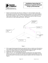
Step 6
Attach the reflector panels (with skirts) by placing them on the ribs and sliding them
inward carefully guiding them until the rib and panel holes align. Place the seam hard-
ware in the fourth hole from the outboard edge on both sides of the panel to set panel
bay spacing, finger tighten only. Install remaining reflector panel hardware, finger tight
only. Note: Panels should be installed opposite each other to ensure proper balancing
of the enclosure assembly. Panel 1, Panel 7, Panel 4, Panel 10, etc. as shown in Figure
7. All panels are interchangeable except panels 1, 2 and 12 due to Logo positioning. Do
not install panel 6 or tighten any panel hardware at this time.
Figure 7
Note: All panels are interchangeable
except panels 1, 2 and 12.
Reference Panel 1 to rear view of hub
to identify top.
Note: All reflector panel hardware
is 1/4-20 x 1-1/4” Socket Head
Capscrews (45055-2), 1/4” Lock
Washers (9974-15) and 1/4” Hex
Nuts (9999-57).
Reference Drawing 240272
Note: Do not install panel six at
this time to allow easier access to
reflector center for future compo-
nent installation.
12:00
6:00
3:00
9:00

Subreflector
Support Brackets
Step 1
18
Installation Procedures
Attach four 206278 lifting tabs across the second and third pairs of reflector seam holes
from reflector center on ribs 1, 4, 7 and 10, as shown in Figure 8. Note: Do not fully
tighten lifting tab hardware at this time.
Figure 8
206278
Lifting Tab
1/4 x 1-1/4”
Socket Head
Capscrew
(45055-2)
1/4”
Lock
Washer
(9974-15)
1/4”
Hex
Nut
(9999-57)
Note: To be removed after reflec-
tor installation on ground mount.
Reference Drawing 240272

Step 2
Step 3
19
Installation Procedures
Attach the four 302518 Subreflector Support Brackets at the 15th (outer most) reflector
panel hole position from reflector center on ribs 2, 5, 8, and 11 as shown in Figure 9.
Note: Do not fully tighten subreflector support bracket hardware at this time.
Figure 9
Check reflector panels to ensure seam widths are even and panels are not overlapped
or interfering with each other. If needed gently rock the reflector back and forth to help
even the panel seam gaps.
1/4” Lock Washer
(9974-15)
1/4 x 1-1/4” Socket Head
Capscrew (45055-2)
1/4” Hex Nut
(9999-57)
302518
Subreflector Strut
Support Bracket
Panel
Reference Drawing 240272

Rotating Tube
Assembly
Step 1
Step 2
Step 3
20
Installation Procedures
Note: Applicable feed installation drawings are included with each feed system.
Install 302356 Rotating Tube Assembly as shown in Figure 10. Note: Rotating Tube
must be attached to Hub prior to attaching support struts to Rotating Tube.
Ensure 302507 Support Struts attach to ribs 2, 5, 8 and 11 as shown. Note: Ensure all
support struts are attached to same side of reflector rib and rotating tube mounting tab.
Fully tighten mounting hardware except for 3 bolts that attach polarization drive as shown
in Figure 11.
Upon completion of the installation of the feed rotating tube assembly, install reflector
panel #6 as described in Step 6 on page 17.
Tighten reflector panel seam hardware in concentric circles in a clockwise direction
beginning with inner hardware and progressively working outward.
Figure 10
302356
Rotating Tube Assembly
302507
Rotating Tube
Support Strut
302507
Rotating Tube
Support Strut
3/8”
Hex Nut
(9999-60)
3/8”
Lock Washer
(9974-63)
3/8”
Flat Washer
(9997-145)
Rib or Rotating Tube
302507
Rotating Tube
Support Strut
1/2” ID x 1” OD
Flat Washer
(9997-65)
1/2 x 1/2”
Shoulder Bolt
(9858-19)
302511
Rib
302649
Hub
302356
Rotating Tube
Assembly
3/8 x 1-3/4” Bolt (9963-146),
Flat Washer (9997-146),
Lock Washer (9974-63)
and Nut (9999-60)
Reference Drawing 240272
Install Reflector
Panel 6
Apply Sealant
368036-4
between
surfaces.
/