
004_03
Instructions for installation,
use and maintenance
07/2007
ELECTRIC FRY-TOP
AGB 604/WP
·
AGB 606/WP
·
AGB 605/WP
AGB 609/WP
AGB 610/WP
AGB 551/WP
·
AGB 553/WP
·
AGB 552/WP
AGB 558/WP
·
AGB 560/WP
·
AGB 559/WP
AGB 536/WP
·
AGB 538/WP
·
AGB 537/WP
AGB 543/WP
·
AGB 544/WP
·
AGB 545/WP

004
-
03 - Electric fry-top
2
Models and dimensions page 3
Technical data 9
Installation instructions 10
Installation 10
Legal and technical requisites 10
Installation 10
Wiring 10
Unipotential 10
Start-up 10
Using the appliance 11
Ignition 11
Special precautions 11
INDEX
Cleaning and taking care
of the appliance
page 11
What to do if not using the appliance for
a long time 11
What to do if something goes wrong 11
Maintenance 11
WEEE Directive 11
Wiring diagrams 12-15
Warning 16

BCDA BCDA
BA BA
C
D
004
-
03 - Electric fry-top
3
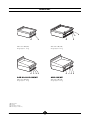
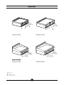
400 x 650 x 300 (440)
Weight approx. 35 kg
600 x 650 x 300 (440)
Weight approx. 48 kg
AGB 604-605-606/WP
400 x 650 x 300 (440)
Weight approx. 35 kg
AGB 609/WP
600 x 650 x 300 (440)
Weight approx. 48 kg
Main switch
Fat tray
Pilot lamp (voltage)
Pilot lamp (resistances)
Dimensions
A
B
C
D

A
A
B
C
D
A
B
C
D
A
004
-
03 - Electric fry-top
4
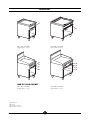
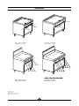
Main switch
Fat tray
Pilot lamp (voltage)
Pilot lamp (resistances)
400 x 700 x 870 (1080)
Weight approx. 69 kg
600 x 700 x 870 (1080)
Weight approx. 82 kg
AGB 551-552-553/WP
400 x 700 x 870 (1080)
Weight approx. 69 kg
600 x 700 x 870 (1080)
Weight approx. 82 kg
Dimensions
A
B
C
D

BCDA ADC
CDA
B
CDA
A
D
D
A
C
C
B
B
A
C
D
A
C
D
004
-
03 - Electric fry-top
5
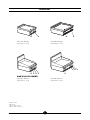
600 x 650 x 300 (440)
Weight approx. 48 kg
800 x 650 x 300 (510)
Weight approx. 70 kg
800 x 650 x 300 (440)
Weight approx. 70 kg
AGB 610/WP
600 x 650 x 300 (440)
Weight approx. 48 kg
Main switch
Fat tray
Pilot lamp (voltage)
Pilot lamp (resistances)
Dimensions
A
B
C
D

BCDA
CDA
A
C
D
A
D
C
ADCB
C
ADCB
A
A
004
-
03 - Electric fry-top
6
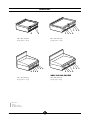
600 x 700 x 870 (1080)
Weight approx. 82 kg
600 x 700 x 870 (1080)
Weight approx. 82 kg
AGB 558-559-560/WP
800 x 700 x 870 (1080)
Weight approx. 102 kg
800 x 700 x 870 (1080)
Weight approx. 102 kg
Main switch
Fat tray
Pilot lamp (voltage)
Pilot lamp (resistances)
Dimensions
A
B
C
D

BCDA
B
DAC
BA
BA
004
-
03 - Electric fry-top
7
400 x 700 x 300 (440)
Weight approx. 35 kg
600 x 700 x 300 (440)
Weight approx. 48 kg
AGB 536-537-538/WP
400 x 700 x 300 (510)
Weight approx. 35 kg
600 x 700 x 300 (510)
Weight approx. 48 kg
Main switch
Fat tray
Pilot lamp (voltage)
Pilot lamp (resistances)
Dimensions
A
B
C
D

DAC
BCDA
BA
AD
DA
C
C
B
AD
DA
C
C
B
004
-
03 - Electric fry-top
8
600 x 700 x 300 (440)
Weight approx. 48 kg
800 x 700 x 300 (510)
Weight approx. 70 kg
600 x 700 x 300 (510)
Weight approx. 48 kg
AGB 543-544-545/WP
800 x 700 x 300 (510)
Weight approx. 70 kg
Main switch
Fat tray
Pilot lamp (voltage)
Pilot lamp (resistances)
Dimensions
A
B
C
D

004
-
03 - Electric fry-top
9
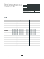
Technical data
The data plate is located on the rigth hand side of the con-
trol panel and contains all the data needed for connecting
it up to the mains electricity supply.
TIPO/TYPE
CAT/KAT GAS/GAZ G30 G31 G20 G25
II2H3B/P P mbar 30 30 20 -
II2H3+ P mbar 30 37 20
-
-
II2H3+ P mbar 28 37 20 -
25II2L3B/P P mbar 30 30
II2ELL3B/P P mbar 50 50 20 20
II2E+3+ P mbar 28 37 20 25
II2H3B/P P mbar 50 50 20 -
I2E P mbar - - 20 -
--II2H3B/P P mbar 30 30
II2H3+ P mbar 28 37 20 -
--
--
I3B/P P mbar 30 30
I3+ P mbar 28 37
SE FI DK CZ SK SI
IT CH PT
ES IE GB GR
NL
DE
FR BE
AT CH
LU
EE LV LT
EE LV LT
NO MT CY IS HU
CY
MOD.
MOD.
ART.
N.
N.
Qn kW
m
3
/h
MADE IN ITALY
Predisposto a gas: - Gas preset: - Prevu pour gaz:
Eingestelt für Gas: - Preparado para gas: -
Geschuckt voor:
V AC kW Hz
THE APPLIANCE MUST BE CONNECTED IN COMPLIANCE WITH THE LAWS IN FORCE
AND INSTALLED IN A WELL-VENTILATED ROOM. READ THE INSTRUCTION MANUALS
BEFORE INSTALLING AND USING THE APPLIANCE.
THE APPLIANCE MUST BE INSTALLED BY QUALIFIED PERSONNEL.
Model
AGB 604-605-606/WP
AGB 536-537-538/WP
AGB 551-552-553/WP
AGB 609/WP
AGB 610/WP
AGB 543-544-545/WP
AGB 558-559-560/WP
FRY-TOP
Dim.: LxWxH (total h)
of work surface
400 x 650 x 300 (440)
400 x 700 x 300 (510)
400 x 700 x 870 (1080)
400 x 650 x 300 (440)
400 x 700 x 300 (510)
400 x 700 x 870 (1080)
600 x 650 x 300 (440)
600 x 700 x 300 (510)
600 x 700 x 870 (1080)
600 x 650 x 300 (440)
600 x 700 x 300 (510)
600 x 700 x 870 (1080)
600 x 650 x 300 (440)
600 x 700 x 300 (510)
600 x 700 x 870 (1080)
600 x 650 x 300 (440)
600 x 700 x 300 (510)
600 x 700 x 870 (1080)
800 x 650 x 300 (440)
800 x 700 x 300 (510)
800 x 700 x 870 (1080)
800 x 650 x 300 (440)
800 x 700 x 300 (510)
800 x 700 x 870 (1080)
Voltage rating
230 V 3 or 400 V 3N
230 V 3 or 400 V 3N
230 V 3 or 400 V 3N
230 V 3 or 400 V 3N
230 V 3 or 400 V 3N
230 V 3 or 400 V 3N
230 V 3 or 400 V 3N
230 V 3 or 400 V 3N
230 V 3 or 400 V 3N
230 V 3 or 400 V 3N
230 V 3 or 400 V 3N
230 V 3 or 400 V 3N
230 V 3 or 400 V 3N
230 V 3 or 400 V 3N
230 V 3 or 400 V 3N
230 V 3 or 400 V 3N
230 V 3 or 400 V 3N
230 V 3 or 400 V 3N
230 V 3 or 400 V 3N
230 V 3 or 400 V 3N
230 V 3 or 400 V 3N
230 V 3 or 400 V 3N
230 V 3 or 400 V 3N
230 V 3 or 400 V 3N
Power
5.0 kW
5.0 kW
5.0 kW
5.0 kW
5.0 kW
5.0 kW
6.75 kW
6.75 kW
6.75 kW
6.75 kW
6.75 kW
6.75 kW
6.75 kW
6.75 kW
6.75 kW
6.75 kW
6.75 kW
6.75 kW
10 kW
10 kW
10 kW
10 kW
10 kW
10 kW
Lead wire / Section
4 x 1.5 mm
2
or
5 x 1.5 mm
2
4 x 1.5 mm
2
or
5 x 1.5 mm
2
4 x 1.5 mm
2
or
5 x 1.5 mm
2
4 x 1.5 mm
2
or
5 x 1.5 mm
2
4 x 1.5 mm
2
or
5 x 1.5 mm
2
4 x 1.5 mm
2
or
5 x 1.5 mm
2
4 x 2.5 mm
2
or
5 x 2.5 mm
2
4 x 2.5 mm
2
or
5 x 2.5 mm
2
4 x 2.5 mm
2
or
5 x 2.5 mm
2
4 x 2.5 mm
2
or
5 x 2.5 mm
2
4 x 2.5 mm
2
or
5 x 2.5 mm
2
4 x 2.5 mm
2
or
5 x 2.5 mm
2
4 x 2.5 mm
2
or
5 x 2.5 mm
2
4 x 2.5 mm
2
or
5 x 2.5 mm
2
4 x 2.5 mm
2
or
5 x 2.5 mm
2
4 x 2.5 mm
2
or
5 x 2.5 mm
2
4 x 2.5 mm
2
or
5 x 2.5 mm
2
4 x 2.5 mm
2
or
5 x 2.5 mm
2
4 x 2.5 mm
2
or
5 x 2.5 mm
2
4 x 2.5 mm
2
or
5 x 2.5 mm
2
4 x 2.5 mm
2
or
5 x 2.5 mm
2
4 x 2.5 mm
2
or
5 x 2.5 mm
2
4 x 2.5 mm
2
or
5 x 2.5 mm
2
4 x 2.5 mm
2
or
5 x 2.5 mm
2

004
-
03 - Electric fry-top
10
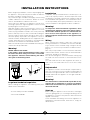
Before beginning installation, remove all packaging from
the appliance. Some parts are protected with an adhesive
film which should be carefully removed.
Any remnants of glue should be thoroughly cleaned using
suitable substances such as benzine. Under no circum-
stances should abrasive substances be used.
Fit the legs to the appliance; the appliance must be level-
led using a spirit level. Slight irregularities can be levelled
by adjusting the feet themselves.
With table models, make sure that the base chosen is ca-
pable of supporting the weight of the appliance. The main
switch or plug should be located in the vicinity of the ap-
pliance and easy of access. We recommend installing the
machine under a range hood so that all the fumes are re-
moved as quickly as possible. If the appliance is to be in-
stalled near walls, dividing walls, kitchen equipment or de-
corative pannelling, these should be in non-inflammable
material or covered with non-inflammable material.
Make sure that all fire prevention standards and safety pre-
cautions are strictly adhered to.
Warning!
MODEL AGB 551-552-553/WP
if this model is going to be mounted on its own, it must
be fixed to the floor. Fixing accessories are included.
The appliance should be fitted following the indica-
tions given in the drawing below.
Legal and technical requisites
When installing the appliance, the following safety stan-
dards must be adhered to:
- Local accident prevention standards
- Current CEI standards.
Installation
Installation, start-up and maintenance should only be car-
ried out by expert personnel. All work required to install
the appliance should be carried out in compliance with all
local standards and regulations. The manufacturers decli-
ne all responsibility where poor performance is due to in-
correct installation in disregard of the above conditions.
Warning!
In compliance with international regulations, when
connecting the appliance to the mains power supply, a
device with a minimum aperture of 3 mm between con-
tacts must be fitted upstream of the appliance, al-
lowing omnipolar disconnection of the appliance from
the mains.
Wiring
When choosing the lead wire, make sure it has the fol-
lowing characteristics: it should be at least of the H07 RN-
F type and its section should be large enough for the ap-
pliance (see "Technical specifications and dimensions",
page 9).
Wire entry on top models is on the back wall, and under-
neath all other models. In both cases the terminal board is
at the front, behind the control panel.
Pass the wire through the core hitch and wire clamp, plug
the leads into their terminals on the board and secure
them.
The earth lead must be a little longerthan the others so
that it is the last lead to disconnect if the wire clamp
breaks.
Unipotential
The appliance must be connected up to a unipotential sy-
stem. The connection screw is located on all top models at
the back on the right hand side, while in other models it is
located underneath the appliance on the right hand side.
It is labelled.
Warning!
The manufacturers cannot be held responsible for any
damage due to inadequate or incorrect installation.
Under such circumstances the guarantee will be consi-
dered null and void.
Start-up
Before using the appliance for the first time, thoroughly
clean the grilling plate (see “Cleaning and Taking Care of
the Appliance”) to remove the protective film of mineral oil
applied in the factory.
Check installation and wiring, then turn the appliance on
following the instructions below, and leave on, empty, for
about 15 mins.
INSTALLATION INSTRUCTIONS
RETRO
BACK
ARRIERE
RÜCKSEITE
1

004
-
03 - Electric fry-top
11
Warning!
- Beware of inexpert handling!
Ignition
Check that the fat tray is in place. Turn on the main switch
upstream of the appliance. Turn the thermostat to any po-
sition between 50°C and 300°C; the pilot lights will come
on; the green one shows that the appliance is on, the yel-
low one shows that the resistances are on.
As soon as the required temperature is reached, the yel-
low light goes off.
To turn the appliance off, simply turn the knob back to '0'.
Note: Appliances AGB 543/WP, AGB 558/WP
have 2 separate, independent cooking areas.
Special precautions
It is recommanded to keep cleaning the plate during use,
using a scraper or a dampf cloth to remove particles of
food which could start smoking and causing unpleasant
smells.
CLEANING AND TAKING CARE OF THE
MACHINE
Warning!
Never clean the appliance with jets of water, whether
direct or pressurised.
Never clean the appliance before it has cooled down.
Before starting to clean the appliance, disconnect from
the mains.
Remove, empty and wash the fat tray.
Remove any remaining particles of food using the scaper
or a dampf cloth.
The plate and steel parts should be washed in warm water
using a neutral detergent.
Rinse the plate with a soft cloth to get rid of all traces of
detergent.
Thoroughly dry the appliance.
Avoid using abrasive or corrosive detergents which could
damage the steel.
After cleaning the appliance, grease the plate with vegeta-
ble oil.
What to do if not using the appliance
for a long time
Thoroughly clean and dry the machine as described.
Disconnect the power supply.
Grease the plate with vegetable oil.
USING THE APPLIANCE
What to do if something goes wrong
If anything goes wrong, immediately turn the appliance
off, then turn off the power supply at the switch located
upstream of the appliance, and call the aftersales depart-
ment.
MAINTENANCE
All maintenance should be carried out by qualified per-
sonnel only. Before carrying out any maintenance work,
unplug the appliance or turn off the switch upstream of the
appliance.
THE 2002/96/EC DIRECTIVE (WEEE):
information to users
This informational note is meant only for owners
of equipment marked with the symbol shown in
Fig. A on the adhesive label featuring the techni-
cal specifications applied on the actual product
(the label also giving the serial number).
This symbol indicates that the product is classified, accor-
ding to the regulations in force, as an item of electrical and
electronic equipment and conforms to EU Directive
2002/96/EC (WEEE) meaning that, at the end of its service
life, it must be treated separately from domestic waste, i.e.
it must be handed in free of charge to a separate waste
electrical and electronic equipment collection centre or re-
turned to the reseller when buying a new equivalent item
of equipment.
The user is responsible for delivering the unit at the end of
its life to the appropriate collection facilities. Failure to do
so shall result in the user being subject to the penalties
prescribed by the legislation in force on waste.
Suitable separated collection so that the unit no longer
used can be sent off for environmentally compatible recy-
cling, treatment and disposal helps avoid possible negati-
ve effects on the environment and on health and facilitates
the recycling of the product's component materials.
For more detailed information on available collection sy-
stems, contact the local waste disposal service or the
shop you purchased the unit from.
Producers and importers fulfil their responsibility for envi-
ronmentally compatible recycling, treatment and disposal
both directly and by joining a collective scheme.

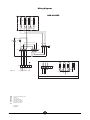
400V 3N
B1
F1
F2
1mA 2 345
6
12
3
456
L1 L2 L3 N
P1P2 P3 12 22 32
11 21 31
P4
H2 H1
R1 R1 R1
1234
230V 3
1mA2 345
6
L1 L 2 L3
12
3
12 22 32
4
4
56
R1
PE
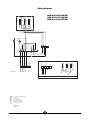
AGB 604-605-606/WP
AGB 536-537-538/WP
AGB 551-552-553/WP
mA
B1
F1
H1
H2
R1
F2
Line input terminal board
Switch
Thermostat
Green pilot lamp
Orange pilot lamp
Resistance 1650 W
Safety thermostat
Total power:
5000 W
004
-
03 - Electric fry-top
12
Wiring diagrams

004
-
03 - Electric fry-top
13
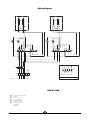
400V 3N
B1
F1
F2
1mA 2 345
6
12
3
456
L1 L2 L3 N
P1P2 P3 12 22 32
11 21 311234
P4
H2 H1
R1 R1 R1 R1
12 22 32
11 21 31
78
230V 3
1mA2 345
6
L1 L 2 L3
12
3
12 22 32
456
78
R1
PE
AGB 609/WP
mA
B1
F1
H1
H2
R1
F2
Line input terminal board
Switch
Thermostat
Green pilot lamp
Orange pilot lamp
Resistance 1650 W
Safety thermostat
Total power:
6750 W
Wiring diagrams

004
-
03 - Electric fry-top
14
1mA2 345
6
L1 L 2 L3
B1
F1
F2
1mA 2 345
6
12
3
4
L1 L2 L3 N
P1
P2 P3 12 22 32
11 21 31
P4
H2 H1
R1 R1
12
34
B1
F1
12
3
4
P1
P2 P3 12 22 32
11 21 31
P4
H2 H1
R1 R1
1234
PE
PE
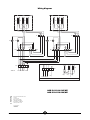
400V 3N
230V 3
AGB 610/WP
mA
B1
F1
H1
H2
R1
F2
Line input terminal board
Switch
Thermostat
Green pilot lamp
Orange pilot lamp
Resistance 1650 W
Safety thermostat
Total power:
6750 W
Wiring diagrams

004
-
03 - Electric fry-top
15
B2
F1
F2
1mA 2 345
6
12
3
456
L1 L2 L3 N
P1P2 P3 12 22 32
11 21 31
P4
H2 H1
R1 R1 R1
31 21 11
32 22 12
1234
B2
F1
F2
12
3
456
P1P2 P3 12 22 32
11 21 31
P4
H2 H1
R1 R1 R1
31 21 11
32 22 12
1234
1 2 345
6
L1 L2 L3
12
3
12 22 32
456
R1
400V 3N
230V 3
PE
PE
mA
AGB 543-544-545/WP
AGB 558-559-560/WP
mA
B1
F1
H1
H2
R1
F2
Line input terminal board
Switch
Thermostat
Green pilot lamp
Orange pilot lamp
Resistance 1650 W
Safety thermostat
Total power:
10000 W
Wiring diagrams

004
-
03 - Electric fry-top
16
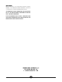
WARNING
DUE TO ITS POLICY OF CONTINUAL PRODUCT IMPRO-
VEMENT, THE MANUFACTURER RESERVES THE RIGHT
TO MAKE ANY CHANGES DEEMED NECESSARY.
THE MANUFACTURER CANNOT BE HELD RESPONSI-
BLE IF THE INSTRUCTIONS CONTAINED IN THIS MA-
NUAL ARE NOT OBSERVED.
THIS DOCUMENTATION IS ONLY INTENDED FOR
QUALIFIED TECHNICIANS WHO ARE AWARE OF THE
RESPECTIVE SAFETY REGULATIONS.
WHIRLPOOL EUROPE srl
V.le Guido Borghi, 27
I – 21025 Comerio – VA
-
 1
1
-
 2
2
-
 3
3
-
 4
4
-
 5
5
-
 6
6
-
 7
7
-
 8
8
-
 9
9
-
 10
10
-
 11
11
-
 12
12
-
 13
13
-
 14
14
-
 15
15
-
 16
16


Ask a question and I''ll find the answer in the document
Finding information in a document is now easier with AI
Related papers
-
Whirlpool AGB 508/WP User guide
-
-
-
-
-
-
Whirlpool AGB 532/WP User guide
-
Whirlpool AGB 433/WP User guide
-
Whirlpool AGB 528/WP User guide
-
Other documents
-
 EMME M64V Datasheet
-
Electrolux EHG7833X User manual
-
Aeg-Electrolux 79553G-M User manual
-
Zanussi ZAF2GX/2 User manual
-
ABB PFEA 111 User manual
-
Progress PAG6430E-B User manual
-
Electrolux EHT6433K User manual
-
IKEA 40182277 PRO D31 AN User guide
-
-
Johnson Controls YORK BCHO-94G Datasheet
