Page is loading ...

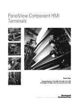
Installation Instructions
PanelView 800 HMI Terminals
Catalog Numbers 2711R-T4T, 2711R-T7T, 2711R-T10T
About This Publication
This document provides instructions on how to install, wire, ground, and troubleshoot PanelView™ 800
terminals. It does not provide information on how to configure or run applications on the following devices:
2711R-T4T, 2711R-T7T, 2711R-T10T
Topic Page
Environment and Enclosure 3
Catalog Number Explanation 6
About the Terminals 6
Install the Terminal 9
USB Ports 14
Choose a Power Supply 15
Remove the Power Terminal Block 16
Connect Power 17
Ground the Terminal 18
Connect Devices 19
Troubleshooting 20
Battery Replacement 21
Specifications 23
Additional Resources 25

2 PanelView 800 HMI Terminals
Publication 2711R-IN001A-EN-P - January 2015
Important User Information
Solid-state equipment has operational characteristics differing from those of electromechanical
equipment. Safety Guidelines for the Application, Installation and Maintenance of Solid State
Controls (Publication SGI-1.1
available from your local Rockwell Automation sales office or online
at http://www.rockwellautomation.com/literature/) describes some important differences
between solid-state equipment and hard-wired electromechanical devices. Because of this
difference, and also because of the wide variety of uses for solid-state equipment, all persons
responsible for applying this equipment must satisfy themselves that each intended application of
this equipment is acceptable.
In no event will Rockwell Automation, Inc. be responsible or liable for indirect or consequential
damages resulting from the use or application of this equipment.
The examples and diagrams in this manual are included solely for illustrative purposes. Because
of the many variables and requirements associated with any particular installation, Rockwell
Automation, Inc. cannot assume responsibility or liability for actual use based on the examples
and diagrams.
No patent liability is assumed by Rockwell Automation, Inc. with respect to use of information,
circuits, equipment, or software described in this manual.
Reproduction of the contents of this manual, in whole or in part, without written permission of
Rockwell Automation, Inc., is prohibited.
Throughout this manual, when necessary, we use notes to make you aware of safety
considerations.
WARNING: Identifies information about practices or circumstances that can cause an
explosion in a hazardous environment, which may lead to personal injury or death,
property damage, or economic loss.
ATTENTION: Identifies information about practices or circumstances that can lead to
personal injury or death, property damage, or economic loss. Attentions help you identify
a hazard, avoid a hazard and recognize the consequences.
SHOCK HAZARD: Labels may be on or inside the equipment (for example,
drive or motor) to alert people that dangerous voltage may be present.
BURN HAZARD: Labels may be on or inside the equipment (for example, drive
or motor) to alert people that surfaces may reach dangerous temperatures.
IMPORTANT
Identifies information that is critical for successful application and understanding of the
product.

PanelView 800 HMI Terminals 3
Publication 2711R-IN001A-EN-P - January 2015
Environment and Enclosure
ATTENTION: This equipment is intended for use in a Pollution Degree 2 industrial
environment, in overvoltage Category II applications (as defined in IEC 60664-1), at
altitudes up to 2000 m (6562 ft) without derating.
This equipment is not intended for use in residential environments and may not provide
adequate protection to radio communication services in such environments.
This equipment is supplied as open-type equipment. It must be mounted within an
enclosure that is suitably designed for those specific environmental conditions that will
be present and appropriately designed to prevent personal injury resulting from
accessibility to live parts. The enclosure must have suitable flame-retardant properties to
prevent or minimize the spread of flame, complying with a flame spread rating of 5VA or
be approved for the application if nonmetallic. The interior of the enclosure must be
accessible only by the use of a tool. Subsequent sections of this publication may contain
additional information regarding specific enclosure type ratings that are required to
comply with certain product safety certifications.
In addition to this publication, see the following:
• Industrial Automation Wiring and Grounding Guidelines, publication 1770-4.1
for
additional installation requirements.
• NEMA Standard 250 and IEC 60529, as applicable, for explanations of the degrees of
protection provided by enclosures.

4 PanelView 800 HMI Terminals
Publication 2711R-IN001A-EN-P - January 2015
North American Hazardous Location Approval
The following information applies when
operating this equipment in hazardous
locations:
Informations sur l’utilisation de cet équipement
en environnements dangereux:
Products marked "CL I, DIV 2, GP A, B, C, D" are suitable for
use in Class I Division 2 Groups A, B, C, D, Hazardous
Locations and nonhazardous locations only. Each product is
supplied with markings on the rating nameplate indicating
the hazardous location temperature code. When combining
products within a system, the most adverse temperature
code (lowest "T" number) may be used to help determine the
overall temperature code of the system. Combinations of
equipment in your system are subject to investigation by the
local Authority Having Jurisdiction at the time of installation.
Les produits marqués "CL I, DIV 2, GP A, B, C, D" ne
conviennent qu'à une utilisation en environnements de Classe
I Division 2 Groupes A, B, C, D dangereux et non dangereux.
Chaque produit est livré avec des marquages sur sa plaque
d'identification qui indiquent le code de température pour les
environnements dangereux. Lorsque plusieurs produits sont
combinés dans un système, le code de température le plus
défavorable (code de température le plus faible) peut être
utilisé pour déterminer le code de température global du
système. Les combinaisons d'équipements dans le système
sont sujettes à inspection par les autorités locales qualifiées
au moment de l'installation.
WARNING: EXPLOSION
HAZARD
• Do not disconnect equipment
unless power has been removed
or the area is known to be
nonhazardous.
• Do not disconnect connections
to this equipment unless power
has been removed or the area is
known to be nonhazardous.
Secure any external
connections that mate to this
equipment by using screws,
sliding latches, threaded
connectors, or other means
provided with this product.
• Substitution of components may
impair suitability for Class I,
Division 2.
• If this product contains
batteries, they must only be
changed in an area known to be
nonhazardous.
AVERTISSEMENT: RISQUE
D’EXPLOSION
• Couper le courant ou s’assurer
que l’environnement est classé
non dangereux avant de
débrancher l'équipement.
• Couper le courant ou s'assurer
que l’environnement est classé
non dangereux avant de
débrancher les connecteurs.
Fixer tous les connecteurs
externes reliés à cet équipement
à l'aide de vis, loquets
coulissants, connecteurs filetés
ou autres moyens fournis avec ce
produit.
• La substitution de composants
peut rendre cet équipement
inadapté à une utilisation en
environnement de Classe I,
Division 2.
• S’assurer que l’environnement
est classé non dangereux avant
de changer les piles.

PanelView 800 HMI Terminals 5
Publication 2711R-IN001A-EN-P - January 2015
Prevent Electrostatic Discharge
ATTENTION: This equipment is sensitive to electrostatic discharge, which can cause internal
damage and affect normal operation. Follow these guidelines when you handle this equipment:
• Touch a grounded object to discharge potential static.
• Wear an approved grounding wrist-strap.
• Do not touch connectors or pins on component boards.
• Do not touch circuit components inside the equipment.
• Use a static-safe workstation, if available.
• Store the equipment in appropriate static-safe packaging when not in use.
ATTENTION: This product is intended to be mounted to a well-grounded mounting surface such
as a metal panel. Additional grounding connections from the power supply's mounting tabs or
DIN rail (if used) are not required unless the mounting surface cannot be grounded. Refer to
Industrial Automation Wiring and Grounding Guidelines, Rockwell Automation publication
1770-4.1
, for additional information.
ATTENTION: If this equipment is used in a manner not specified by the manufacturer, the
protection provided by the equipment maybe impaired.
ATTENTION: Do not place the module in direct sunlight. Prolonged exposure to direct sunlight
could degrade the LCD.
ATTENTION: The USB device port is not intended for Customer use. The USB host port cable is
not to exceed 3.0 m (9.84 ft).

6 PanelView 800 HMI Terminals
Publication 2711R-IN001A-EN-P - January 2015
Catalog Number Explanation
About the Terminals
PanelView 800 terminals are operator interface devices for monitoring and controlling devices attached to a
controller. HMI applications are created using Connected Components Workbench software, then
downloaded to the terminal.
PanelView 800 Terminal – 2711R-T4T
Catalog No. Operator Input Size Display Type
2711R-T4T Touch screen and function keys 4 in. Color TFT
2711R-T7T Touch screen 7 in.
2711R-T10T Touch screen 10 in.
Item Description Item Description
1 Power status LED
(1)
(1)
The Power Status LED is red when in screen saver or dimmer mode and green when in normal (operational) mode.
7 10/100 Mbit Ethernet port
2 Touch display, function keys 8 RS-232 port
3 24V DC power input 9 RS-422 and RS-485 port
4 USB device port
(2)
(2)
The USB device port is not intended for Customer use.
10 USB host port
5 Micro-SD (Secure Digital) card slot 11 Diagnostic status indicator
6 Mounting slots 12 Replaceable real-time clock battery
2
3
6
12
1
10
4
5
67
8
9
11

PanelView 800 HMI Terminals 7
Publication 2711R-IN001A-EN-P - January 2015
PanelView 800 Terminal – 2711R-T7T
Item Description Item Description
1 Power status LED
(1)
(1)
The Power Status LED is red when in screen saver or dimmer mode and green when in normal (operational) mode.
7 Replaceable real-time clock battery
2 Touch display 8 USB host port
3 Mounting slots 9 Diagnostic status indicator
4 RS-422 and RS-485 port 10 Micro-SD (Secure Digital) card slot
5 RS-232 port 11 24V DC power input
6 10/100 Mbit Ethernet port 12 USB device port
(2)
(2)
The USB device port is not intended for Customer use.
21
4 5 63 3
7
8
12
9
11
10

8 PanelView 800 HMI Terminals
Publication 2711R-IN001A-EN-P - January 2015
PanelView 800 Terminal – 2711R-T10T
Parts List
PanelView 800 terminals ship with these items:
•Power terminal block
• RS-422/RS-485 5-pin terminal block
• Lithium battery for real-time clock (pre-installed)
• Panel cutout template
• Mounting levers (4 for 2711R-T4T, 6 for 2711R-T7T, and 8 for 2711R-T10T)
Item Description Item Description
1 Power status LED
(1)
(1)
The Power Status LED is red when in screen saver or dimmer mode and green when in normal (operational) mode.
7 Replaceable real-time clock battery
2 Touch display 8 USB host port
3 Mounting slots 9 Diagnostic status indicator
4 RS-422 and RS-485 port 10 Micro-SD (Secure Digital) card slot
5 RS-232 port 11 24V DC power input
6 10/100 Mbit Ethernet port 12 USB device port
(2)
(2)
The USB device port is not intended for Customer use.
21
4 5 63 3
7
98
10
11
12

PanelView 800 HMI Terminals 9
Publication 2711R-IN001A-EN-P - January 2015
Install the Terminal
Before installing the terminal in a panel, review minimum clearances, panel guidelines, panel cutout
dimensions, and product dimensions.
Minimum Spacing
Plan for adequate space around the terminal, inside the enclosure, for ventilation and cabling. Consider heat
produced by other devices in the enclosure.
The ambient temperature around the terminal must be 0…50 °C (32…122 °F).
Mounting Angle
You can mount the terminal vertically against the panel, or tilted forward or backwards, up to a 60° angle. For
mounting angles greater than 60°, the operating temperature is restricted to 40 °C (104 °F).
Panel Guidelines
Supporting panels must be at least 16 gauge to provide proper sealing against water and dust and to provide
proper support. The panel surface must be flat and free of imperfections to maintain an adequate seal and
NEMA Type ratings.
Catalog No. Top Bottom Sides Back
2711R-T4T 51 mm (2 in.) 51 mm (2 in.) 51 mm (2 in.) 51 mm (2 in.)
2711R-T7T 51 mm (2 in.) 51 mm (2 in.) 25 mm (1 in.) 51 mm (2 in.)
2711R-T10T 51 mm (2 in.) 25 mm (1 in.) 25 mm (1 in.) 51 mm (2 in.)
WARNING: When you insert or remove the micro-SD Card while power is on, an
electrical arc can occur. This could cause an explosion in hazardous location installations.
Be sure that power is removed or the area is nonhazardous before proceeding.
TIP
The minimum spacing requirements are sufficient for connecting cables and inserting or
removing a memory card. Plan for additional clearance if using the USB host port on the
back of the unit.

10 PanelView 800 HMI Terminals
Publication 2711R-IN001A-EN-P - January 2015
Panel Cutout Dimensions
Use the template shipped with your terminal to mark the cutout dimensions.
Mount the PanelView 800 Terminal in a Panel
Mounting levers secure the PanelView 800 terminal to the panel.
Follow these steps to mount the terminal in a panel.
1. Cut an opening in the panel using the template shipped with the terminal.
2. Make sure the sealing gasket is properly positioned on the terminal.
This gasket forms a compression type seal. Do not use sealing compounds.
3. Place the terminal in the panel cutout.
Catalog No. Height, Approx., mm (in.) Width, Approx., mm (in.)
2711R-T4T 99.0 ±0.5 (3.89 ±0.02) 119.0 ±0.5 (4.68 ±0.02)
2711R-T7T 125.0 ±0.5 (4.92 ±0.02) 179.0 ±0.5 (7.05 ±0.02)
2711R-T10T 206.0 ±0.5 (8.11 ±0.02) 269.0 ±0.5 (10.59 ±0.02)
ATTENTION: Follow these guidelines when mounting the terminal in a panel.
• Disconnect all electrical power from the panel before making the panel cutout.
• Make sure the area around the panel cutout is clear.
• Take precautions so metal cuttings do not enter any components already installed in the
panel.
• Failure to follow these instructions may result in personal injury or damage to panel
components.
WARNING: If you connect or disconnect the serial cable with power applied to this module or
the serial device on the other end of the cable, an electrical arc can occur. This could cause an
explosion in hazardous location installations.
Be sure that power is removed or the area is nonhazardous before proceeding.
WARNING: When used in a Class I, Division 2, hazardous location, this equipment must be
mounted in a suitable enclosure with proper wiring method that complies with the governing
electrical codes.
IMPORTANT
The terminal temperature must be greater than 0 °C (32 °F) during panel installation.

PanelView 800 HMI Terminals 11
Publication 2711R-IN001A-EN-P - January 2015
4. Insert all mounting levers into the mounting slots on the terminal.
Slide each lever until the short, flat side of lever touches the surface of the panel.
5. When all levers are in place, slide each lever an additional notch or two until you hear a click.
6. Rotate each lever in direction indicated until it is in the final latch position.
Follow the latching sequence for the optimum terminal fit.
Mounting slots
Short, flat side of mounting lever
Mounting levers
Rotate until notch in lever aligns with
proper alignment mark on terminal.
Notch
Six alignment marks
Latching sequence for 2711R-T4T Latching sequence for 2711R-T7T Latching sequence for 2711R-T10T
14
32
14
32
56
14
32
57
86

12 PanelView 800 HMI Terminals
Publication 2711R-IN001A-EN-P - January 2015
Use this table as a guide to provide an adequate gasket seal between the terminal and the panel.
Remove the PanelView 800 Terminal from the Panel
Follow these steps to remove the terminal from the panel.
1. Disconnect power to the terminal.
2. Release the mounting lever by rotating it in the direction indicated, slide it to the bottom of the
mounting slot, and remove it.
3. Grip the sides of the bezel and gently pull the terminal out of the panel opening.
Terminal Markings for
Alignment
Lever
Position
Panel Thickness Range
Typical
Gauge
1 1.52…2.01 mm (0.060…0.079 in.) 16
2 2.03…2.64 mm (0.08…0.104 in.) 14
3 2.67…3.15 mm (0.105…0.124 in.) 12
4 3.17…3.66 mm (0.125…0.144 in.) 10
5 3.68…4.16 mm (0.145…0.164 in.) 8/9
6 4.19…4.75 mm (0.165…0.187 in.) 7
6
1
1
2
3
4
5
6
44881

PanelView 800 HMI Terminals 13
Publication 2711R-IN001A-EN-P - January 2015
Product Dimensions
PanelView 800 Terminal – 2711R-T4T
PanelView 800 Terminal – 2711R-T7T
a
b
c
d
a
b
c
d

14 PanelView 800 HMI Terminals
Publication 2711R-IN001A-EN-P - January 2015
PanelView 800 Terminal – 2711R-T10T
USB Ports
You can power USB peripherals directly from the PanelView 800 terminal. If the USB peripheral is not
powered directly from the PanelView USB port either:
• install the USB peripheral in the same enclosure as the PanelView terminal and make sure it is
connected to the same ground system.
• connect to the USB peripheral through a galvanically isolated hub.
PanelView 800 Dimensions
Catalog No.
Height, Approx. Width, Approx. Overall Depth,
Approx.
Mounted Depth,
Approx.
abcd
2711R-T4T 116 mm (4.57 in.) 138 mm (5.43 in.) 43 mm (1.69 in.) 39 mm (1.54 in.)
2711R-T7T 144 mm (5.67 in.) 197 mm (7.76 in.) 54 mm (2.13 in.) 50 mm (1.97 in.)
2711R-T10T 225 mm (8.86 in.) 287 mm (11.30 in.) 55 mm (2.17 in.) 51 mm (2.01 in.)
WARNING: If you connect or disconnect the communications cable with power applied to this
module or any device on the network, an electrical arc can occur. This could cause an explosion
in hazardous location installations.
Be sure that power is removed or the area is nonhazardous before proceeding.
a
b
c
d

PanelView 800 HMI Terminals 15
Publication 2711R-IN001A-EN-P - January 2015
Choose a Power Supply
Use a dedicated 24V DC, Class 2 Safety Extra-low Voltage (SELV) or Protective Extra-low Voltage (PELV)
power supply to power each PanelView Terminal.
PanelView 800 devices have been tested to operate with 1606-XLP power supplies. To use another power
supply, review the criteria in the table.
WARNING: If you connect or disconnect the USB cable with power applied to this module or any
device on the USB network, an electrical arc can occur. This could cause an explosion in
hazardous location installations.
Be sure that power is removed or the area is nonhazardous before proceeding.
ATTENTION: Use a Class 2, Safety Extra-low Voltage (SELV), or Protective Extra-low Voltage
(PELV) power supply as required by local wiring codes for your installation. These power supplies
provide protection so that under normal and single-fault conditions, the voltage between the
conductors, and between conductors and functional earth, does not exceed a safe value.
WARNING: When you insert or remove connection(s) while power is on, an electrical arc can
occur. This could cause an explosion in hazardous location installations.
Be sure that power is removed or the area is nonhazardous before proceeding. Repeated
electrical arcing causes excessive wear to contacts on both the module and its mating connector.
Worn contacts may create electrical resistance that can affect module operation.
WARNING: Do not connect directly to line voltage. Line voltage must be supplied by a suitable,
approved isolating transformer or power supply having short circuit capacity not exceeding
100 VA maximum or equivalent.
Power Supply Criteria
If the PanelView 800 terminal Use a Description
Connects to equipment with isolated
communication ports
SELV or PELV power supply Other equipment can share this power
supply with the PanelView 800 device
provided that no ground loops are
created. A PELV power source internally
connects the negative power terminal
to chassis ground.
Does not connect to other equipment
Connects to equipment with nonisolated
communication ports
Dedicated, isolated, and
ungrounded SELV source to
power each terminal
This prevents ground loops from
damaging the devices.

16 PanelView 800 HMI Terminals
Publication 2711R-IN001A-EN-P - January 2015
Remove the Power Terminal Block
PanelView 800 terminals ship with a power terminal block installed. You can remove the power terminal
block for ease of installation, wiring, and maintenance.
Follow these steps to remove the terminal block.
1. Insert the tip of a small, flat-blade, screwdriver into the terminal block access slot.
2. Gently pry the terminal block away from the terminal to release the locking mechanism.
Follow these steps to replace the terminal block.
1. Press the terminal block base in first with the block leaning outward.
2. Gently push the top of the terminal block back to a vertical position to snap in the locking tab.
ATTENTION: Disconnect all power before installing or replacing components. Failure to
disconnect power may result in electrical shock or damage to the terminal.
WARNING: When you connect or disconnect the Removable Power Terminal Block (RTB) while
the module is powered, an electrical arc can occur. This could cause an explosion in hazardous
location installations.
Be sure that power is removed or the area is nonhazardous before proceeding.
Access slot

PanelView 800 HMI Terminals 17
Publication 2711R-IN001A-EN-P - January 2015
Connect Power
All PanelView 800 terminals connect to a 24V DC power source. The table shows the power ratings for each
device.
The internal, nonisolated power supply is protected against reverse polarity of the DC+ and DC-
connections.
The input power terminal block supports these wire sizes.
Power Ratings
Catalog No. Input Voltage Range Power Consumption, Max
2711R-T4T 18…32V DC (24V DC nom) 9 W (0.39 A)
2711R-T7T 11 W (0.40 A)
2711R-T10T 14 W (0.48 A)
ATTENTION: Connecting DC+ or DC- source to the functional earth terminal may damage the
device. Miswiring the DC+ source to the DC- input while connected to other equipment through
nonisolated ports may cause a ground loop current and damage the device.
WARNING: Use supply wires suitable for 30 °C (86 °F) above surrounding ambient.
WARNING: If you connect or disconnect wiring while the power is on, an electrical arc can
occur. This could cause an explosion in hazardous location installations.
Be sure that power is removed or the area is nonhazardous before proceeding.
Wire Specifications for Input Power Terminal Block
Wire Type Dual-wire Gauge
(1)
(1)
Two-wire maximum per terminal.
Single-wire
Gauge
Terminal Screw
Torque
Stranded or solid Cu 90 °C (194 °F) 0.33…1.31 mm
2
(22…16 AWG)
0.33…2.08 mm
2
(22…14 AWG)
0.45…0.56 Nm
(4…5 lb-in.)
ATTENTION: Disconnect all power before installing or replacing components. Failure to
disconnect power may result in electrical shock or damage to the terminal.

18 PanelView 800 HMI Terminals
Publication 2711R-IN001A-EN-P - January 2015
Follow these steps to connect power.
1. Verify that the terminal is not connected to a power source.
2. Secure the 24V DC power wires to the terminal block.
3. Secure the functional earth ground wire to the functional earth ground terminal screw on the
terminal block.
4. Apply 24V DC power to the terminal.
Ground the Terminal
PanelView 800 terminals have a functional earth terminal that you must connect to a low-impedance earth
ground. The functional earth connection is on the power input terminal block. The negative power terminal
is not internally connected to earth ground.
The functional earth terminal wiring requires a minimum wire gauge.
ATTENTION: Do not wire more than 2 conductors on any single terminal.
ATTENTION: The functional earth connection to ground is mandatory. This connection is
required for noise immunity, reliability, and Electromagnetic Compliance (EMC) with the
European Union (EU) EMC directive for CE-mark conformance.
Functional Earth Wire Specifications
FE Symbol Wire Type Wire Gauge Terminal Screw Torque
Stranded or solid Cu 90 °C (194 °F) 2.08…3.31 mm
2
(14…12 AWG)
0.45…0.56 Nm (4…5 lb-in)
Functional earth ground
to ground bus
DC+
DC-

PanelView 800 HMI Terminals 19
Publication 2711R-IN001A-EN-P - January 2015
Connect Devices
Use these cables for connecting devices to PanelView 800 terminals.
RS-422/RS-485 Port
The RS-422/RS-485 port is an isolated port that supports point-to-point communications. RS-422
supports both Full-Duplex and Half-Duplex mode. RS-485 only supports Half-Duplex mode.
• In Full-Duplex mode, both devices can transmit and receive simultaneously.
The transmit and receive pair are wired individually.
• In Half-Duplex mode, only one device can transmit at a time while the other device receives. A
single differential, twisted pair connects to both receive and transmit pairs (R and T and on one
wire, R- and T- on the other).
The RS422/485 port has integrated 120 ohm termination between the R and R- signal pair. This value is
compatible with RS422 and RS485 electrical specifications. Additional termination on the PanelView 800
terminal end of communication cables is not required.
Cables for PanelView 800 Terminals
Cat. No. Description
2711P-CBL-EX04 Ethernet crossover CAT5 cable 4.3 m (14 ft)
1747-CP3 Serial 9-pin D-shell to 9-pin D-shell null modem cable
1761-CBL-PM02 Serial 9-pin D-shell to 8-pin mini DIN cable, 2 m (6.56 ft)
2711C-CBL-AB03 RS-485 5-pin to RJ45 cable
RS-422/RS-485 Connector Pinout
Pin Signal
1T
2T–
3R
4R–
5 S (Shield)

20 PanelView 800 HMI Terminals
Publication 2711R-IN001A-EN-P - January 2015
Troubleshooting
If your terminal does not start up correctly, check for adequate power and indicator states during powerup.
Check for Adequate Power
A terminal that does not receive adequate power could cause unpredictable behavior.
Verify the power requirements in the Specifications table.
Interpret the LED Indicators at Startup
The PanelView 800 terminals have indicators to isolate operating problems. They can be seen through the
battery cover on the back of the unit.
• Comm indicator for communications
• Fault indicator for hardware faults
At startup, the Fault indicator is off, except for a few brief flashes, and the Comm indicator is on. If the
indicators remain off, check the power cable. After a successful startup, both indicators are off and controlled
by the application running on the terminal.
The table shows the indicator states if the terminal stops during startup.
Fault Indicator States During Startup
Fault (Red)
Indicator State
Comm (Green)
Indicator State
Description Recommended Action
Potentially recoverable errors
Blinking Off Last firmware download failed. Reload the firmware.
Blinking Blinking EBC boot loader firmware failed or
is missing.
Reload the firmware.
Blinking On Windows CE OS firmware failed or
is missing.
Reload the firmware.
Nonrecoverable or fatal errors
On Off Fatal hardware error. Replace the terminal.
/