Page is loading ...

Installation Instructions
Original Instructions
POINT I/O Cold Junction Compensation
Wiring Base Assembly
Catalog Number
1734-TBCJC
Topic Page
Important User Information 2
Environment and Enclosure 3
Prevent Electrostatic Discharge 4
Special Conditions for Safe Use 4
Electrical Safety Considerations 5
Before You Begin 5
Install the Wiring Base 6
Install the Removable Terminal Block 6
Remove a Mounting Base 8
Specifications 9

2 Rockwell Automation Publication 1734-IN583C-EN-P - January 2019
POINT I/O Cold Junction Compensation Wiring Base Assembly
Important User Information
Solid-state equipment has operational characteristics differing from those of electromechanical
equipment. Safety Guidelines for the Application, Installation and Maintenance of Solid-state Controls
(Publication SGI-1.1
available from your local Rockwell Automation sales office or online at
http://www.rockwellautomation.com/literature/
) describes some important differences between solid-
state equipment and hard-wired electromechanical devices. Because of this difference, and also because of
the wide variety of uses for solid-state equipment, all persons responsible for applying this equipment
must satisfy themselves that each intended application of this equipment is acceptable.
In no event will Rockwell Automation, Inc. be responsible or liable for indirect or consequential damages
resulting from the use or application of this equipment.
The examples and diagrams in this manual are included solely for illustrative purposes. Because of the
many variables and requirements that are associated with any particular installation, Rockwell
Automation, Inc. cannot assume responsibility or liability for actual use based on the examples
and diagrams.
No patent liability is assumed by Rockwell Automation, Inc. with respect to use of information, circuits,
equipment, or software described in this manual.
Reproduction of the contents of this manual, in whole or in part, without written permission of
Rockwell Automation, Inc., is prohibited.
Throughout this manual, when necessary, we use notes to make you aware of safety considerations.
WARNING: Identifies information about practices or circumstances that can cause an
explosion in a hazardous environment, which may lead to personal injury or death, property
damage, or economic loss.
ATTENTION: Identifies information about practices or circumstances that can lead to
personal injury or death, property damage, or economic loss. Attentions help you identify a
hazard, avoid a hazard and recognize the consequences.
SHOCK HAZARD: Labels may be on or inside the equipment (for example, drive or motor)
to alert people that dangerous voltage may be present.
BURN HAZARD: Labels may be on or inside the equipment (for example, drive or motor) to
alert people that surfaces may reach dangerous temperatures.
IMPORTANT
Identifies information that is critical for successful application and understanding of
the product.

Rockwell Automation Publication 1734-IN583C-EN-P - January 2019 3
POINT I/O Cold Junction Compensation Wiring Base Assembly
Environment and Enclosure
ATTENTION:
This equipment is intended for use in a Pollution Degree 2 industrial
environment, in overvoltage Category II applications (as defined in EN/IEC 60664-1),
at altitudes up to 2000 m (6562 ft) without derating.
This equipment is not intended for use in residential environments and may not
provide adequate protection to radio communication services in such environments.
This equipment is supplied as open-type equipment for indoor use. It must be
mounted within an enclosure that is suitably designed for those specific
environmental conditions that will be present and appropriately designed to
prevent personal injury resulting from accessibility to live parts. The enclosure
must have suitable flame-retardant properties to prevent or minimize the spread
of flame, complying with a flame spread rating of 5V A or be approved for the
application if nonmetallic. The interior of the enclosure must be accessible only by
the use of a tool. Subsequent sections of this publication may contain more
information regarding specific enclosure type ratings that are required to comply
with certain product safety certifications.
In addition to this publication, see the following:
• Industrial Automation Wiring and Grounding Guidelines,
publication 1770-4.1
, for additional installation requirements.
• NEMA Standard 250 and EN/IEC 60529, as applicable, for explanations of the
degrees of protection provided by enclosures.
ATTENTION: Read this document and the documents listed in the Additional
Resources section about installation, configuration, and operation of this
equipment before you install, configure, operate, or maintain this product. Users
are required to familiarize themselves with installation and wiring instructions in
addition to requirements of all applicable codes, laws, and standards.
Installation, adjustments, putting into service, use, assembly, disassembly, and
maintenance are required to be carried out by suitably trained personnel in
accordance with applicable code of practice. In case of malfunction or damage, no
attempts at repair should be made. The module should be returned to the
manufacturer for repair. Do not dismantle the module.

4 Rockwell Automation Publication 1734-IN583C-EN-P - January 2019
POINT I/O Cold Junction Compensation Wiring Base Assembly
Prevent Electrostatic Discharge
Special Conditions for Safe Use
ATTENTION: This equipment is sensitive to electrostatic discharge, which can
cause internal damage and affect normal operation. Follow these guidelines
when you handle this equipment:
• Touch a grounded object to discharge potential static.
• Wear an approved grounding wriststrap.
• Do not touch connectors or pins on component boards.
• Do not touch circuit components inside the equipment.
• Use a static-safe workstation, if available.
• Store the equipment in appropriate static-safe packaging when not in use.
ATTENTION:
• This product is grounded through the DIN rail to chassis ground. Use zinc
plated chromate-passivated steel DIN rail to assure proper grounding. The use
of other DIN rail materials (for example, aluminum or plastic) that can corrode,
oxidize, or are poor conductors, can result in improper or intermittent
grounding. Secure DIN rail to mounting surface approximately every 200 mm
(7.8 in.) and use end-anchors appropriately. Be sure to ground the DIN rail
properly. Refer to Industrial Automation Wiring and Grounding Guidelines,
publication 1770-4.1
, for more information.
• Do not remove or replace an Adapter Module while power is applied.
Interruption of the backplane can result in unintentional operation or
machine motion.
• Do not discard the end cap. Use this end cap to cover the exposed
interconnections on the last mounting base on the DIN rail. Failure to do so
could result in equipment damage or injury from electric shock.
• If this equipment is used in a manner not specified by the manufacturer, the
protection provided by the equipment may be impaired.
At the end of its life, this equipment should be collected separately from any
unsorted municipal waste.

Rockwell Automation Publication 1734-IN583C-EN-P - January 2019 5
POINT I/O Cold Junction Compensation Wiring Base Assembly
Electrical Safety Considerations
Before You Begin
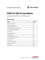
The wiring base consists of a base (1) and a removable terminal block (Catalog
Number 1734-RTBCJC) (4). The 1734-TBCJC wiring base uses screw-
clamp termination.
Use this diagram to identify the external features of the module.
POINT I/O™ Cold Junction Compensation Wiring Base Assembly
ATTENTION:
• This equipment is certified for use only within the surrounding air temperature
range of -20…+55 °C (-4…+131 °F). The equipment must not be used
outside of this range.
• Use only a soft dry anti-static cloth to wipe down equipment. Do not use any
cleaning agents.
For use with 1734-IT2I Thermocouple Input Module
Description Description
1 Wiring base 4 Removable Wiring Block (RTB)
2 Mechanical keying (orange) 5 Interlocking side pieces
3 RTB removal handle 6 DIN rail locking screw (orange)
1
2
4
3
5
6
+
_
+
_
Shield
3
4
5
6
7
0
1
0
1

6 Rockwell Automation Publication 1734-IN583C-EN-P - January 2019
POINT I/O Cold Junction Compensation Wiring Base Assembly
Install the Wiring Base
1. Position the wiring base vertically above the installed units (adapter,
power supply, or existing module).
2. Slide the wiring base down allowing the interlocking side pieces to
engage the adjacent module or adapter.
3. Press firmly to seat the mounting base on the DIN rail. The mounting
base snaps into place.
4. To remove the wiring base from the DIN rail, remove the module, and
use a small bladed screwdriver to rotate the base locking screw to a
vertical position. This releases the locking mechanism. Then lift straight
up to remove.
Install the Removable Terminal Block
A Removable Terminal Block (RTB) is supplied with your wiring base assembly.
To remove, pull up on the RTB handle. This allows the mounting base to be
removed and replaced as necessary without removing any of the wirings. To
reinsert the Removable Terminal Block, proceed as follows.
1. Insert the end opposite the handle into the base unit.
This end has a curved section that engages with the wiring base.
2. Rotate the terminal block into the wiring base until it locks itself
in place.
WARNING: When you connect or disconnect the Removable Terminal Block (RTB)
with field-side power applied, an electrical arc can occur. This can cause an
explosion in hazardous location installations.
Be sure that power is removed or the area is nonhazardous before proceeding.

Rockwell Automation Publication 1734-IN583C-EN-P - January 2019 7
POINT I/O Cold Junction Compensation Wiring Base Assembly
3. If an I/O module is installed, snap the RTB handle into place on
the module.
WARNING: For 1734-RTBS and 1734-RTB3S, to latch and unlatch the wire, insert
a bladed screwdriver (catalog number 1492-N90 – 3 mm diameter blade) into
the opening at approximately 73° (blade surface is parallel with top surface of the
opening) and push up gently.
0
1
Hook the RTB end into the
mounting base end, and rotate
until it locks into place.
44012
73°
85°

8 Rockwell Automation Publication 1734-IN583C-EN-P - January 2019
POINT I/O Cold Junction Compensation Wiring Base Assembly
Remove a Mounting Base
To remove a wiring base, you must remove any module installed in the base and
any installed module to the right of the base. Remove the removable terminal
block (if wired).
1. Snap open the RTB removal handle, or remove the removable
terminal block.
2. Squeeze the module locking mechanism and pull up to remove
the module(s).
3. Turn the wiring base locking screw to a vertical position to unlock the
base from the DIN rail.
4. Slide the wiring base up to release it from its mating units.
Refer to the user manual for keying information, specifications, and information
on how to configure your module.
WARNING: For 1734-TOPS and 1734-TOP3S, to latch and unlatch the wire, insert
a bladed screwdriver (catalog number 1492-N90 – 3 mm diameter) into the
opening at approximately 97° (blade surface is parallel with top surface of the
opening) and press in (do not push up or down).
97°

Rockwell Automation Publication 1734-IN583C-EN-P - January 2019 9
POINT I/O Cold Junction Compensation Wiring Base Assembly
Specifications
General Specifications
Attribute Value
Terminal base screw torque 0.5...0.6
N•m (5...7 lb-in.)
Supply voltage 28.8V DC, 120/240V AC
Supply current 10 A maximum
Dimensions, approx., HxWxD
65 x 12 x 133.4 mm
(2.56 x 0.472 x 5.25 in.)
Wire category
(1)
(1) Use this Conductor Category information for planning conductor routing as described in the appropriate System Level
Installation Manual. Also refer to Industrial Automation Wiring and Grounding Guidelines, publication 1770-4.1
, for
more information.
2 - on signal ports
Wire size
0.25…2.5 mm
2
(24…14 AWG) thermocouple wire
1.2 mm (3/64 in.) insulation maximum
Mass 97.5 g (3.44 oz)
Environmental Specifications
Attribute Value
Temperature, operating
IEC 60068-2-1 (Test Ad, operating cold),
IEC 60068-2-2 (Test Bd, operating dry heat),
IEC 60068-2-14 (Test Nb, operating thermal shock):
-20…+55 °C (-4…+131 °F)
Temperature, surrounding air, max. 55 °C (131 °F)
Temperature, nonoperating
IEC 60068-2-1 (Test Ab, unpackaged nonoperating cold),
IEC 60068-2-2 (Test Bb, unpackaged nonoperating dry heat),
IEC 60068-2-14 (Test Na, unpackaged nonoperating thermal shock):
-40…+85 °C (-40…+185 °F)
Relative humidity
IEC 60068-2-30 (Test Db, unpackaged damp heat):
5…95% noncondensing
Vibration
IEC 60068-2-6 (Test Fc, operating):
5 g @ 10...500Hz
Shock, operating
IEC 60068-2-27 (Test Ea, unpackaged shock):
30 g

10 Rockwell Automation Publication 1734-IN583C-EN-P - January 2019
POINT I/O Cold Junction Compensation Wiring Base Assembly
Shock, nonoperating
IEC 60068-2-27 (Test Ea, unpackaged shock):
50 g
Emissions IEC 61000-6-4
ESD immunity
IEC 61000-4-2:
6 kV contact discharges
8 kV air discharges
Radiated RF immunity
IEC 61000-4-3:
10V/m with 1 kHz sine-wave 80% AM from 80...2000 MHz
10V/m with 200 Hz 50% pulse 100% AM @ 900 MHz
10V/m with 200 Hz 50% pulse 100% AM @ 1890 MHz
10V/m with 1 kHz sine-wave 80% AM from 2000...2700 MHz
EFT/B Immunity
IEC 61000-4-4:
±2 kV at 5 kHz on power ports
±2 kV at 5 kHz on signal ports
Surge transient immunity
IEC 61000-4-5:
±1 kV line-line (DM) and ±2 kV line-earth (CM) on signal ports
Conducted RF immunity
IEC 61000-4-6:
10V rms with 1 kHz sine-wave 80% AM from 150 kHz…80 MHz
Enclosure type rating None (open-style)
Environmental Specifications
Attribute Value

Rockwell Automation Publication 1734-IN583C-EN-P - January 2019 11
POINT I/O Cold Junction Compensation Wiring Base Assembly
Certifications
Certification
(When Product Is Marked)
(1)
(1) See the Product Certification link at http://www.rockwellautomation.com/global/certification/overview.page for
Declaration of Conformity, Certificates, and other certification details.
Value
c-UL-us
Terminal blocks – Component
UL recognized. See UL File E195367.
CE
European Union 2014/30/EU EMC Directive, compliant with:
• EN 61326-1; Measurement/Control/Laboratory use, Industrial requirements
• EN 61000-6-2; Industrial Immunity
• EN 61000-6-4; Industrial Emissions
• EN 61131-2; Programmable Controllers (Clause 8, Zone A & B)
European Union 2011/65/EU RoHS, compliant with:
• EN 50581; Technical documentation
European Union 2014/35/EU LVD, compliant with:
• EN 61131-2; Programmable Controllers (Clause 11)
RCM
Australian Radiocommunications Act, compliant with:
• AS/NZS CISPR 11; Industrial Emissions
KC
Korean Registration of Broadcasting and Communications Equipment,
compliant with:
• Article 58-2 of Radio Waves Act, Clause 3
EAC
• Russian Customs Union TR CU 020/2011 EMC Technical Regulation
• Russian Customs Union TR CU 004/2011 LV Technical Regulation

12 Rockwell Automation Publication 1734-IN583C-EN-P - January 2019
POINT I/O Cold Junction Compensation Wiring Base Assembly
Notes:

Rockwell Automation Publication 1734-IN583C-EN-P - January 2019 13
POINT I/O Cold Junction Compensation Wiring Base Assembly
Notes:

14 Rockwell Automation Publication 1734-IN583C-EN-P - January 2019
POINT I/O Cold Junction Compensation Wiring Base Assembly
Notes:

Rockwell Automation Publication 1734-IN583C-EN-P - January 2019 15
POINT I/O Cold Junction Compensation Wiring Base Assembly
Rockwell Automation Support
Use the following resources to access support information.
Documentation Feedback
Your comments will help us serve your documentation needs better. If you have any
suggestions on how to improve this document, complete the How Are We Doing? form
at http://literature.rockwellautomation.com/idc/groups/literature/documents/du/ra-
du002_-en-e.pdf.
Technical Support
Center
Knowledgebase Articles, How-to Videos,
FAQs, Chat, User Forums, and Product
Notification Updates.
www.rockwellautomation.com/
knowledgebase
Local Technical
Support Phone
Numbers
Locate the phone number for your country.
www.rockwellautomation.com/global/
support/get-support-now.page
Direct Dial Codes
Find the Direct Dial Code for your product.
Use the code to route your call directly to a
technical support engineer.
www.rockwellautomation.com/global/
support/direct-dial.page
Literature Library
Installation Instructions, Manuals,
Brochures, and Technical Data.
www.rockwellautomation.com/literature
Product Compatibility
and Download Center
(PCDC)
Get help determining how products interact,
check features and capabilities, and find
associated firmware.
www.rockwellautomation.com/global/
support/pcdc.page

Allen-Bradley, POINT I/O, Rockwell Automation, Rockwell Software and TechConnect are trademarks of Rockwell Automation, Inc.
EtherNet/IP is a trademark of ODVA, Inc.
Trademarks not belonging to Rockwell Automation are property of their respective companies.
Rockwell Otomasyon Ticaret A.Ş., Kar Plaza İş Merkezi E Blok Kat:6 34752 İçerenköy, İstanbul, Tel: +90 (216) 5698400
Rockwell Automation maintains current product environmental information on its website at
http://www.rockwellautomation.com/rockwellautomation/about-us/sustainability-ethics/product-environmental-compliance.page
.
Publication 1734-IN583C-EN-P - January 2019 PN-528081
Supersedes Publication 1734-IN583B-EN-P - July 2015 Copyright © 2019 Rockwell Automation, Inc. All rights reserved. Printed in Singapore.
/