Page is loading ...

OPERATOR MANUAL
Harmony® vLED Surgical Lighting System
(10/15/14) P136824-104


i
Introduction Operator Manual P136824-104
A WORD FROM STERIS CORPORATION
©2014, STERIS Corporation. All rights reserved. Printed in U.S.A.
This manual contains important information on proper use and care
of this surgical lighting system. All operators and department heads
are urged to carefully review and become familiar with the warnings,
cautions and instructions contained herein. Your new surgical
lighting fixture features an advanced, state-of-the-art design, with
cool, shadow-reduced light and ease of maneuverability. It produces
light of a quality necessary for the most demanding and complex of
surgical procedures.
A thorough preventive maintenance program is essential for safe
and proper operation of your surgical light. You are encouraged to
contact STERIS concerning our annual maintenance agreement.
Under the terms of this agreement, preventive maintenance,
adjustments and replacement of worn parts are done on a
scheduled basis to verify lighting fixture performance according to
its specifications and to help avoid untimely or costly downtime.
STERIS maintains a nationwide staff of well-equipped, factory-
trained technicians to provide this service, as well as expert repair
services. Contact STERIS for details. STERIS is also able to provide
Customer training; contact STERIS Customer Service for more
information.
Any ancillary equipment (e.g., monitors, video recorders, etc.) that is
to be used with this lighting system must comply with all applicable
medical equipment standards.
Complete instructions for uncrating and installing this equipment, as
well as an equipment drawing, have been furnished. If missing,
contact STERIS and provide the unit’s serial number and model
numbers to receive replacement copies.
Indications for Use The Harmony® vLED Surgical Lighting System is a variable pattern,
variable intensity surgical lighting fixture designed to provide visible
illumination of the surgical field or the patient for the operating room
staff.
Advisory The following is an important message from STERIS about the
advantages and limitations associated with the use of high
intensity surgical lighting systems.
Because of the variety of surgical procedures performed and the
wide range of individual preferences of surgical staffs, it is desirable
that a surgical lighting system be capable of selective control across
a wide range of illumination intensities. The Illuminating Engineering
Society (IES) stresses that in addition to providing control of
intensity, surgical lighting systems should provide shadow control,
correct color rendition, and a suitable depth of field to provide sharp,
consistent lighting into deep body cavities. As illumination levels
increase, however, radiant heat also increases. Therefore, the IES
cautions that for most operations, radiant heat should be kept to a
minimum. The user of surgical lights should utilize the lowest
possible illumination level suitable for the procedure, especially in

ii
P136824-104 Operator Manual Introduction
certain neurological or intestinal procedures on delicate, thin, dry or
abnormal tissue. Furthermore, for the protection of surgically exposed
tissues and for the comfort and efficiency of the surgeon and assistants,
radiant energy can be effectively controlled by limiting the time of
exposure at higher illumination levels. Extra care must be taken when the
light fields from multiple lightheads are overlapped on the surgical site,
since this condition creates a risk of too much heat.
An international standard for the safety of surgical lights established by the
International Electrotechnical Commission (IEC) sets minimum and
maximum levels of illumination and maximum levels of radiant heat that
can be emitted from a single surgical luminaire. The vLED Surgical
Lighting System has been designed to comply with this international
standard and to provide a wide range of illumination levels while
minimizing the potentially damaging infrared heat in the surgical field.
The illumination level of Harmony vLED Surgical Lights can be adjusted
through several intensity settings via conveniently located controls on
either the wall-mounted control center or the lighthead handle. The
illumination level also decreases as the pattern size increases. Maximum
illuminance can exceed 12,000 fc for the smallest pattern size of the
Harmony vLED lighthead and can be adjusted by intensity control or
pattern size control throughout the entire range specified by the IEC.
Manufactured by:
STERIS Corporation
2720 Gunter Park East
Montgomery, AL 36109 • USA
Distributed by:
STERIS Surgical Technologies SAS
645, rue des Châtaigniers
BAT 405-B2-F
45774 Saran Cedex
FRANCE
Class 1 Equipment
Ordinary Equipment (enclosed equipment without protection of ingress of
water)
Equipment not suitable for use in the presence of a flammable anesthetic
mixture with air or oxygen or nitrous oxide.
Suitable for continuous operation.
The base language of this document is ENGLISH.
Any translations must be made from the base
language document.
STERIS Ltd.
Chancery House
190 Waterside Road
Hamilton Industrial Park
Leicester LE5 1QZ UK

iii
Table of Contents Operator Instructions P136824-104
TABLE OF CONTENTS
Section
Number Description Page
1 Safety Precautions ........................................................................................................................ 1-1
2 Installation Verification ................................................................................................................. 2-1
2.1 Pre-operation Checklist ......................................................................................................................... 2-1
2.1.1 Check Suspension Movement ..................................................................................................... 2-1
2.1.2 Check System Operation ............................................................................................................. 2-1
2.1.3 Check Optional Video Camera Operation.................................................................................... 2-2
2.2 Check Optional Monitor Support Arms ................................................................................................. 2-2
2.3 Harmony vLED Optical Performance..................................................................................................... 2-3
2.4 Environmental Conditions...................................................................................................................... 2-4
2.5 Power Requirements ............................................................................................................................. 2-4
3 Operating Instructions .................................................................................................................. 3-1
3.1 Intensity Controls ................................................................................................................................... 3-1
3.1.1 Activate the Harmony vLED System ............................................................................................ 3-1
3.1.2 Harmony vLED Wall Control Unit................................................................................................. 3-2
3.1.3 Surgeon's Intensity Control Buttons............................................................................................. 3-3
3.2 Harmony vLED Lightheads vLED Module Status Indications................................................................ 3-4
3.3 Lighthead Positioning ............................................................................................................................ 3-5
3.4 Harmony vLED Lighthead Pattern Adjustment ...................................................................................... 3-6
3.5 Lighthandle and Lighthandle Cover ....................................................................................................... 3-7
3.5.1 Installing and Using Lighthandle and Lighthandle Cover ............................................................. 3-7
3.5.2 Metal Sterilizable Handle ............................................................................................................. 3-7
3.6 Install Monitor Yoke Handle Disposable Sterile Covers......................................................................... 3-8
3.7 Harmony vLED Monitor Arms .............................................................................................................. 3-10
3.8 Video Camera Installation or Removal ................................................................................................ 3-11
3.9 Install Camera Disposable Sterile Cover ............................................................................................ 3-12
3.10 Video Camera Operation ..................................................................................................................... 3-13
3.11 Guidelines for Maximizing Video Image .............................................................................................. 3-15
3.12 ACT Enabled System .......................................................................................................................... 3-16
4 Cleaning the Equipment................................................................................................................ 4-1
4.1 Cleaning Equipment .............................................................................................................................. 4-1
4.2 General Cleaning/Disinfecting Procedure.............................................................................................. 4-2
4.3 Areas To Be Cleaned Before Each Use ................................................................................................ 4-3
5 Operator Troubleshooting ............................................................................................................ 5-1
5.1 Operator Troubleshooting Table ............................................................................................................ 5-1
5.2 Wall Control Faults ................................................................................................................................ 5-3

iv
P136824-104 Operator Instructions Table of Contents
Section
Number Description Page
TABLE OF CONTENTS
6 Maintenance................................................................................................................................... 6-1
6.1 Preventive Maintenance ........................................................................................................................ 6-1
6.2 Inspect Suspension ............................................................................................................................... 6-1
6.3 Inspect Wall Control............................................................................................................................... 6-1
6.4 Optional Service Disconnect Switch ...................................................................................................... 6-2
7 Replacement Parts ........................................................................................................................ 7-1
8 Waste Disposal Guidelines........................................................................................................... 8-1
9 AppendiX–EMC Compliance Technical Data ............................................................................. 9-1

LIST OF FIGURES
v
Table of Contents Operator Instructions P136824-104
Figure 3-1. Harmony vLED Wall Control (with Optional Camera Controls) ............................................................3-1
Figure 3-2. Harmony vLED Lighthead.....................................................................................................................3-3
Figure 3-3. Lighthead vLED Module Status Indicator .............................................................................................3-4
Figure 3-4. Lighthead Positioning ...........................................................................................................................3-5
Figure 3-5. Light Pattern Adjustment ......................................................................................................................3-6
Figure 3-6. Standard Lighthandle............................................................................................................................3-9
Figure 3-7. Harmony vLED Monitor Arm ...............................................................................................................3-10
Figure 3-8. Optional Camera Installation ..............................................................................................................3-11
Figure 3-9. Install Disposable Sterile Camera Cover ............................................................................................3-12
Figure 6-1. Optional Service Disconnect Switch .....................................................................................................6-2

vi
P136824-104 Operator Instructions Table of Contents
Healthcare
Capital Equipment

vii
P136824-104 Installation Instructions Table of Contents
LIST OF TABLES
Table Title Page
Table 1-1. Definition of Symbols....................................................................................................................... 1-5
Table 2-1. Harmony vLED Lighthead Optical Performance ............................................................................. 2-3
Table 3-1. vLED Intensity Control..................................................................................................................... 3-2
Table 3-2. Harmony vLED Camera Features Summary................................................................................. 3-13
Table 3-3. Brightness and Focus Mode Summary ......................................................................................... 3-14
Table 5-1. Operator Troubleshooting ............................................................................................................... 5-1
Table 5-2. Wall Control Fault Codes ................................................................................................................ 5-3
Table 7-1. Harmony® vLED Lighting System Replacement Parts.................................................................... 7-2
Table 9-1. Guidance and Manufacturer’s Declaration – Electromagnetic Emissions – for all ME Equipment
and ME Systems (per IEC 60601-1-2 clause 5.2.2.1 c) Table 1).................................................... 9-1
Table 9-2. Guidance and Manufacturer’s Declaration –
Electromagnetic Immunity for all ME Equipment and ME Systems ................................................ 9-2
Table 9-3. Guidance and Manufacturer’s Declaration – Electromagnetic Immunity for ME equipment
and ME Systems that are not Life-Supporting ................................................................................ 9-3
Table 9-4. Recommended Separation Distances Between Portable and Mobile RF communications
Equipment and the Harmony vLED System.................................................................................... 9-4

viii
Table of Contents Installation Instructions P136824-104
Healthcare
Capital Equipment

1-1
Safety Precautions Operator Manual P136824-104
1
The following Safety Precautions must be observed when operating or servicing this Harmony® vLED Surgical
Lighting System. WARNING indicates the potential for personal injury and CAUTION indicates the potential for
damage to equipment. For emphasis, certain Safety Precautions are repeated throughout the manual. It is
important to review ALL Safety Precautions before operating or servicing the unit.
Strictly following these Safety Precautions enhances your ability to safely and effectively utilize the unit and helps
the Customer avoid improper maintenance methods which may damage the unit or render it unsafe. It is
important to understand that these Safety Precautions are not exhaustive; Customers are encouraged to develop
their own safety policies and procedures to enhance and complement these Safety Precautions.
WARNING – PERSONAL INJURY HAZARD AND/OR EQUIPMENT DAMAGE HAZARD:
WARNING – PERSONAL INJURY HAZARD:
WARNING – POSSIBLE PATIENT INJURY HAZARD:
Safe and reliable operation of this equipment requires regularly scheduled preventive maintenance, in
addition to the regular performance of routine maintenance. Contact STERIS Service Engineering to
schedule preventive maintenance.
Repairs and adjustments to this equipment should be made only by fully qualified service personnel.
Maintenance performed by inexperienced, unqualified personnel or installation of unauthorized parts
could cause personal injury, invalidate the warranty or result in costly equipment damage. Contact
STERIS Service regarding service options.
Do not attempt to clean lighthead unless power is turned off and the lighthead has cooled sufficiently.
Do not attempt to adjust suspension system. Refer servicing to qualified service personnel.
Avoid looking directly at high-intensity light from the lighthead. Eye injury may result.
FPM monitor arm uses adjustable tension force to support equipment weight. Do not remove equipment
from the arm’s shelf unless the arm has been locked in place by a trained and authorized technician.
Do not modify this equipment without authorization of the manufacturer.
Connecting electrical equipment to the Multiple Socket Outlet (MSO) effectively leads to creating a
Medical Electrical (ME) system, and the result can be a reduced level of safety.
Failure to engage the lighthandle cover completely may result in cover falling from lighthead during the
procedure.
!
!
!
!
!
!
!
!
!
SAFETY PRECAUTIONS 1

1-2
P136824-104 Operator Manual Safety Precautions
WARNING – STERILITY ASSURANCE HAZARD:
WARNING – BIOHAZARD:
WARNING – DISPOSAL HAZARD:
WARNING – SHOCK AND BURN HAZARD:
WARNING – EXPLOSION HAZARD:
WARNING – ELECTRIC SHOCK HAZARD:
Do not use the surgeon’s control buttons unless a disposable sterile cover is installed. If the sterilizable
lighthandle (metal) is used without a disposable cover, the sterility of the surgical environment may be
compromised.
Sterile disposable covers for handles and camera are intended for single use only.
Universal precautions must be observed when disposing of any single use disposable item.
This product contains materials which may require disposal through appropriately licensed and permitted
hazardous waste management firms. The materials listed in SECTION 8 are contained within the Harmony
vLED Surgical Lighting System. When disposing of the lighting fixture or its parts, ensure proper disposal
of hazardous and other regulated waste in compliance with national, state and local regulations.
Disconnect all utilities to lighting fixture before servicing. Do not install the lighting fixture unless all
utilities have been properly locked out. Always follow OSHA Lockout-Tagout and electrical safety-related
work practice standards.
To avoid risk of electric shock, this equipment must only be connected to a supply mains with protective
earth.
Do not use this lighting system in the presence of flammable anesthetics.
Do not remove covers or perform service other than as described in this operator manual. Refer servicing
to qualified service personnel.
The OFF position on the system ON/OFF touch pad of the wall control turns off control to camera and
lightheads, but system is still energized. This mode is referred to as STANDBY, and the ON/OFF LED
flashes once per second while system is in this mode.
The ON/OFF switch under the canopy only removes power from the load side of the system. Any system
wiring located between this switch and the utility junction box is still energized.
!
!
!
!
!
!
!
!
!
!

1-3
Safety Precautions Operator Manual P136824-104
WARNING – PINCHING HAZARD:
WARNING – LASER RADIATION:
Pinch points are created during extreme articulation of the suspension system. Do not place hands on or
near the suspension knuckle during lighthead articulations.
CAUTION: Class 3R invisible laser radiation when canopy opened. Avoid direct eye exposure.
CAUTION: Use of controls or adjustments or performance of procedures other than those specified in the
manual may result in hazardous radiation exposure.
CAUTION: CLASS 1 LASER PRODUCT
CAUTION – POSSIBLE EQUIPMENT DAMAGE:
Appropriate components of this lighting system have been tested and found in compliance with IEC
60601-1-2: 2007, Medical Electrical Equipment – Part 1: General Requirements for Safety;
Electromagnetic Compatibility (EMC). There is, however, a potential for electromagnetic or other
interference between this equipment and other devices. Should you experience interference, relocate this
device or minimize the use of the affected equipment while this device is in operation.
When installing or removing the video camera, be careful to place it in a secure location to prevent it from
rolling, dropping and breaking. Also, to avoid scratching the lens surface, do not stand camera up with
lens side facing down.
Use of any disinfectant solution OTHER than Germicidal Surface Wipes Disinfecting/Deodorizing/
Cleaning Wipes may cause discoloration of the lens surface. Other cleaning solutions have NOT been
tested for compatibility or effectiveness. Always follow manufacturer instructions for concentrations and
use of cleaning products.
Use only recommended cleaning/disinfecting and/or anti-static agents on this light. Staining, pitting and/
or discoloration could occur if a phenolic-, iodophor-, or glutaraldehyde-based disinfectant is used on the
surfaces of this light. Also, use of alcohol or aerosol spray cleaner/disinfectants containing a substantial
amount of alcohol in the formula can damage the polycarbonate lens.
Cleaning and disinfecting agents used on this lighting system must be certified by their manufacturer to
be compatible with the following materials: polycarbonate, polyetherimide, santoprene.
DO NOT SPRAY any cleaning product directly onto the lighthead, modem chassis or any system
components. Dampen a soft cloth with the cleaning solution and wring out the excess moisture.
Do not use floor cleaners on this equipment.
Do not scratch optical coating on accessible portions of optic assembly when cleaning; always wear
rubber gloves and use only a clean, white, lint-free cloth when wiping external surfaces.
Prevent leakage of fluids into interior of lighthead or wall control. Any such leakage could impair or
damage the lighting system.
!
!
!
!
!
!
!
!
!
!
!
!
!

1-4
P136824-104 Operator Manual Safety Precautions
Portable and mobile RF communications equipment used in close proximity to the wall control or canopy
controls units may temporarily affect the operation of the Harmony vLED System equipment.
Use of ACCESSORIES, transducers and cables other than those specified, with the exception of
transducers and cables sold by the manufacturer of this device as replacement parts for internal
components, may result in increased EMISSIONS or decreased IMMUNITY of the Harmony vLED
System. Accessories or replacement parts not listed in the Operator or Maintenance Manuals should not
be used.
Avoid potential EMISSIONS interference. The Harmony vLED system should not be used adjacent to or
stacked with other equipment. If adjacent or stacked use is necessary, the equipment or system should
be observed to verify normal operation in the configuration in which it will be used.
Accessories or replacement parts not listed in the Operator or Maintenance Manuals should not be used
as it may affect EMC or result in equipment damage.
Medical Electrical Equipment needs special precautions regarding EMC and needs to be installed and
put into service according to the EMC information provided in this manual.
Do not clean control center with Betadine®a solutions or allow such solutions to contact keypad and
display surfaces. Use of such solutions may cause discoloration of control center keypad and display.
Do not bump lightheads into walls or other equipment.
The FPM monitor spring arm lacks an upper-limit stop. Use care when moving the arm upward to help
avoid hitting the ceiling or objects above the arm.
a. Betadine® is a registered trademark of Purdue Pharma, L.P.
CAUTION – POSSIBLE EQUIPMENT DAMAGE: (CONTINUED)
!
!
!
!
!
!
!
!

1-5
Safety Precautions Operator Manual P136824-104
The following symbols appear on the Harmony vLED Surgical Lighting System:
Table 1-1. Definition of Symbols
Symbol Definition
ON-OFF
Lighthead (designation and intensity)
LED Module(s) Requires Service
Protective Earth (Ground)
Attention, consult manual for further instructions
Consult instructions before use
Hot, Potential Burn Hazard
Serial Number of Unit
V~ Voltage Rating of Unit, Alternating Current
A Amperage Rating of Unit
Hz Frequency Rating of Unit
+ Increase Intensity (Surgeon's Control Buttons or Wall Control)
- Decrease Intensity (Surgeon's Control Buttons or Wall Control)
Camera ON/OFF indicator
SN

1-6
P136824-104 Operator Manual Safety Precautions
Zoom
Rotate
Manual Focus
Auto Mode (Brightness or Focus)
Potential Impact Hazard
Potential Pinch-Point Hazard
Brightness
Battery Backup
Fault
Laser Radiation
Table 1-1. Definition of Symbols (Continued)
Symbol Definition

2-1
Installation Verification Operator Manual P136824-104
Equipment Drawings showing all of the space and utility
requirements were sent to the purchaser after the order for this
surgical light was received. The clearance space shown on the
drawing is necessary for proper installation, operation and
maintenance of this fixture.
Installation and Uncrating Instructions were furnished with the
Lighting Fixture.
If any of these documents are missing or misplaced, contact
STERIS, giving the serial and model numbers of the equipment.
Replacement copies will be sent to you promptly.
2.1 Pre-operation
Checklist
Before operating the equipment, complete the pre-operation
checklist. It is essential to the safe operation and continuing
maintenance of this equipment to verify that the installation is
complete and correct.
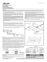
2.1.1 Check Suspension
Movement
Check all suspension joints for compromised integrity, such as loose
fasteners or components.
❑Verify that suspension system moves through all articulations
smoothly without binding. Lightheads and monitors should move
smoothly and easily. When positioned, the lighthead support
arms (or monitor support arms) should not drift. If binding or
drifting is present in suspension movements, call your STERIS
service representative to make adjustments.
2.1.2 Check System Operation Verify that electrical power to the control center is on.
.❑When wall control ON/OFF switch is OFF, wall control ON/OFF
LED flashes. Turn control ON by pressing wall control ON/OFF
touch pad. Verify that wall control touch pads function. Check
intensity levels for each system lighthead. If optional camera
module is installed, check camera controls.
NOTE: Turn power OFF to each lighthead using intensity
controls, and to optional camera (if installed) when testing is
complete.
❑Check vLED Module Failure Indicators: If LED Module(s)
Requires Service graphic on wall control display is lit, one or
more modules may require service.
❑Check vLED Module Failure LED: If the LED on any of the
lightheads is blinking, one or more LED modules may require
service. Check lighthead status LED.
❑Check Intensity Controls at Each Surgeon's Control: Verify
that the intensity level can be increased and decreased at each
lighthead using the surgeon's control buttons.
WARNING – ELECTRIC SHOCK
HAZARD: Do not remove covers
or perform service other than as
described in this operator
manual. Refer servicing to
qualified service personnel.
!
WARNING – PINCHING HAZARD:
Pinch points are created during
extreme articulation of the
suspension system. Do not place
hands on or near the suspension
knuckle during lighthead
articulations.
!
WARNING – ELECTRIC SHOCK
HAZARD: The OFF position on
the system ON/OFF touch pad of
the wall control turns OFF control
to camera and lightheads, but
system remains energized. This
mode is referred to as STANDBY,
and the ON/OFF LED flashes once
per second while system is in this
mode.
!
vLED Module(s) Requires Service
Indicator
INSTALLATION VERIFICATION 2

2-2
P136824-104 Operator Manual Installation Verification
2.1.3 Check Optional Video
Camera Operation
Turn the vLED system ON. Install video camera in lighthandle (see
SECTION 3.8, VIDEO CAMERA INSTALLATION OR REMOVAL, PAGE 3-11.
Press the Camera Control button on the touch pad to turn ON the
camera.
❑Video: Verify that a clear signal is reaching the video display
device (monitor) from the camera. (Check cable connection
between video output connector at control center and monitor, if
necessary.)
❑Harmony vLED Wall Control: Verify zoom, rotation and focus
functions with the control center switches.
2.2 Check Optional
Monitor Support Arms
The Harmony vLED Surgical Lighting System can include up to three
lightheads and up to two monitor arms (max.). Verify smooth and
easy movement (without binding) through the monitor arm(s) ranges
of articulations. Verify that monitor, or monitors, receive video
signals.
Camera Control Button
on Wall Control

2-3
Installation Verification Operator Manual P136824-104
2.3 Harmony vLED
Optical Performance
Important: Values are typical for the small pattern size at highest
intensity setting (unless otherwise noted) at 100 cm (39-3/8") from
the lighthead. Definitions and measurements are in accordance with
IEC 60601-2-41.
Table 2-1. Harmony vLED Lighthead Optical Performance
Feature Harmony vLED
Maximum Central Illuminance 160,000 lux
Peak Total Irradiance < 500 W/m2
Pattern Size
Fixed 18 cm (7")
Adjustable 18 cm (7") – 28 cm (11")
D50 Diameter 62% of small beam pattern (see
Pattern Size)
Depth of Illumination (to 20%)
(to 60%)
97 cm (38")
53 cm (21")
Color Temperature (CCT) 4,400K ± 300
General Color Rendering Index (CRI) Up to 96
Deep Saturated Red Color Rendering
Index (R9)
Up to 98
Shadow Control
Single Mask 44%
Double Mask 43%
Cavity 100%
Single mask w/ Cavity 44%
Double mask w/ Cavity 43%
LED Life 50,000 hours at full intensity

2-4
P136824-104 Operator Manual Installation Verification
2.4 Environmental
Conditions
2.5 Power
Requirements
Three Lighthead System (system running)
For sealed-ceiling applications Control Center Ambient = 60°C (140°F) Maximum
Room Ambient = 20 to 25°C (68 to 77°F)
Interstitial space temperature has minimal effect on the canopy ambient in a completely sealed ceiling
application.
For vented-ceiling applications (1/4" [6 mm]
minimum gap between ceiling and ceiling plate)
Control Center Ambient = 60°C (140°F) Maximum
Room Ambient = 20 to 25°C (68 to 77°F)
To avoid adverse thermal effects on canopy control electronics, thermal contributions from interstitial space
and room ambient temperatures must NOT result in canopy ambient temperatures exceeding 60°C (140°F).
Recommended Transport/Storage Temperature
(not exceeding 15 weeks)
2 to 38°C (36 to 100°F)
Recommended Relative Humidity 30 to 75%
Atmospheric Pressure 500 to 1060 hPascals
Two-Lighted System 100 – 240 Vac, 50/60 Hz
5-2A
500 Watts at 100 Vac
480 Watts at 240 Vac
Typical Lighthead Wattage Harmony vLED: 40 Watts
Recommended ac line fuse current rating 20 A
/