Page is loading ...


EB-UHD-SDI
Evaluation Board Kit User Guide
Rev.3
PDS-061679 September 2019
2 of 41
Semtech
Proprietary & Confidential
www.semtech.com
Revision History
Contents
1. Quick Start Guide.............................................................................................................................................6
1.1 System Block Diagram ......................................................................................................................6
1.2 Start Up Sequence ..............................................................................................................................7
1.3 Configuration 1 — Internal Loopback
(EBK-GS12142/82 Only) ...........................................................................................................................9
1.4 Configuration 2 — External Loopback .................................................................................... 10
1.5 Configuration 3 — Optical Mode (EBK-GS12142/82 Only) .............................................. 11
1.6 Configuration 4 — Cable EQ PRBS Generator ....................................................................... 13
1.7 Configuration 5—Cable Driver PRBS Generator .................................................................. 14
2. Software User Guide.................................................................................................................................... 15
2.1 Installing the SRDVariant Software GUI ................................................................................... 15
2.2 GUI Operation ................................................................................................................................... 19
2.2.1 Getting Started..................................................................................................................... 19
2.2.2 Device Settings Tab............................................................................................................ 20
2.2.3 Main Tab ................................................................................................................................. 20
2.3 Additional GUI Features ................................................................................................................ 22
2.3.1 Cable Driver Misc. Tab ....................................................................................................... 22
2.3.2 Cable Equalizer Misc. Tab .................................................................................................23
2.3.3 PRBS Tab................................................................................................................................. 24
2.3.4 Eye Monitor ........................................................................................................................... 26
3. Schematics ...................................................................................................................................................... 29
4. Board Layout .................................................................................................................................................. 35
5. Bill of Materials............................................................................................................................................... 37
Version ECO Date Changes and/or Modifications
3 048327 September 2019
Further updates made to support the 3rd
revision of the board.
2 046006 March 2019
Updates made to support the 3rd revision
of the Evaluation Board. Updated Figure A,
Figure B, and all Figures in Quick Start
Guide, Software User Guide, Schematics,
Board Layout, and updated the Bill of
Materials.
1 041413 October 2018
Updated Quick Start Guide, Software User
Guide, Schematics, Board Layout, and Bill
of Materials.
0 039462 November 2017 New document.

EB-UHD-SDI
Evaluation Board Kit User Guide
Rev.3
PDS-061679 September 2019
3 of 41
Semtech
Proprietary & Confidential
www.semtech.com
General Description
This document provides guidance on how to use the EB-UHD-SDI evaluation board to
facilitate evaluating the performance of the Semtech devices on the board.
Familiarity with the following product Data Sheets is recommended prior to reading this
document, or using an evaluation board kit.
There are currently three different versions of this board available, which can be
individually ordered to enable evaluation of different Semtech devices.
1. The Semtech devices featured in the kit EBK-GS12341/281 are:
• GS12341 (PDS-061928) 12G UHD-SDI Reclocking Adaptive Cable Equalizer
Single Cable Equalizer Input, Dual Trace Driver outputs
• GS12281 (PDS-061385) 12G UHD-SDI Reclocking
Single Trace Equalizer Input, Dual Cable Driver outputs
2. The Semtech devices featured in the kit EBK-GS12142/82 are:
• GS12142 (PDS-061389) Dual Input 12G UHD-SDI Reclocking Adaptive Cable Equalizer + Trace Equalizer
Dual inputs — Cable Equalizer and Trace Equalizer, Dual Trace Driver outputs
• GS12182 (PDS-061384) 12G UHD-SDI Dual Input Reclocking Cable Driver
Dual Trace Equalizer inputs, Dual Cable Driver outputs
3. The Semtech devices featured in the kit EBK-GS12241/81 are:
• GS12241 (PDS-061386) 12G UHD-SDI Reclocking Adaptive Cable Equalizer
Single Cable Equalizer input, Dual Trace Driver outputs
• GS12281 (PDS-061385) 12G UHD-SDI Reclocking Cable Driver
Single Trace Equalizer input, Dual Cable Driver outputs
Overview
The EB-UHD-SDI evaluation board can be powered and evaluated out-of-the-box as a
standalone kit, with or without software control. Connecting to a PC (using the supplied
USB cable) enables the evaluation of advanced features which are accessible through
the host interface / Graphical User Interface (GUI).
The following features are available out-of-the-box without any configuration required:
• 12G SDI equalization 12G SDI cable driver external routing
• 12G SDI equalization 12G SDI cable driver internal routing [EBK-GS12142/82 only]
• 10G 100Ω SMA TX/RX with SFP+ loopback [EBK-GS12142/82 only]
• 12G PRBS7 generator Cable EQ (100Ω SMA Output)
• 12G PRBS7 generator Cable Driver (SDI Output)
For a quick evaluation, refer to the Quick Start Guide section of this document.
Kit Contents
• Semtech EB-UHD-SDI Evaluation Board, configured as per the kit ordered as described above.
• 2x SMA cables
• 5V Power Supply
• Micro USB Cable (for GUI communication)
Note: SFP+ transceiver is not provided.

EB-UHD-SDI
Evaluation Board Kit User Guide
Rev.3
PDS-061679 September 2019
4 of 41
Semtech
Proprietary & Confidential
www.semtech.com
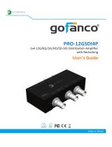
Figure A: EB-UHD-SDI Inputs, Outputs and Power Connections
CD VCCO
SELECT
JP8
3.3V
2.5V
GS12142 or GS12241 Cable Equalizer
(U23)
Optional SFP+ transceiver
(EBK - GS12142/82)
(J2)
GS12182 or GS12281 Cable Driver
(U20)
USB
(J8)
Mode Selector Switch
(SW2)
Output
(J6)
JP7 EQ V
CCO
Select
Output
(J12)
Input
(J4)
Input
(J3)
Input
(J1)
Output
(J5)
Power (+5V)
(J11)
Jumpers
(EBK - GS12142/82)
(JP3, JP6)
Jumpers
(EBK - GS12142/82)
(JP5, JP4)
JP8 CD V
CCO
Select
DECEMBER 2018
EB-UHD SDI REV 3
MADE IN CANADA
Table A: Connector Descriptions
Designator Description
J1 (SDI) Input of the GS12142, GS12241 or GS12341 Cable Equalizer.
J5 (SDO) Output of the GS12182 or GS12281 Cable Driver.
J8
Micro USB – Used to access advanced functionality via GUI. For Software User Guide, see
Section 2.
J3 (TXO_N), J4 (TXO_P) DDI0 – Input to the GS12182 or GS12281 Trace Equalizer.
J6 (RXO_P), J12(RXO_N) DDO0 – Output of the GS12142, GS12241 or GS12341 Trace Driver.
JP8
CD V
CCO
voltage select. Can be set to 2.5V or 3.3V.
J11 +5V Power Supply.
J2 SFP+ transceiver connector.
JP3 (PRSNT), JP4 (TX_RATE),
JP5 (RX_RATE), JP6 (TX_DIS)
Use for configuration of the optical module (not included). Refer to the optical module data
sheet for more information.
JP7
EQ V
CCO
voltage select. Can be set to 1.8V or 2.5V.

EB-UHD-SDI
Evaluation Board Kit User Guide
Rev.3
PDS-061679 September 2019
5 of 41
Semtech
Proprietary & Confidential
www.semtech.com
Figure B: Top Views EBK-GS12142/82 (left), and EBK-GS12241/81 or EBK-GS12341/281 (right)
Figure C: Front View
Figure D: Rear View
CD VCCO
SELECT
JP8
3.3V
2.5V
CD VCCO
SELECT
JP8
3.3V
2.5V
DECEMBER 2018
EB-UHD SDI REV 3
MADE IN CANADA
DECEMBER 2018
EB-UHD SDI REV 3
MADE IN CANADA
(EBK - GS12142/82)
Power (+5V)
Input
(J3)
Input
(J4)
Output
(J12)
Output
(J6)

EB-UHD-SDI
Evaluation Board Kit User Guide
Rev.3
PDS-061679 September 2019
6 of 41
Semtech
Proprietary & Confidential
www.semtech.com
1. Quick Start Guide
1.1 System Block Diagram
Figure 1-1: System Block Diagram
GS12142/
GS12241/
GS12341
SFP+Tr
a
nsceive
r
GS12182
/
G
S
122
81
GS12341/241/281/142/182 Data Path - 75Ω single-ended
GS12341/241/281/142/182 Data Path - 100Ω dierential
7
5Ω BNC
(
J1
)
7
5Ω BNC
(
J5
)
50
Ω
S
MA
(
J6
)
5
0
Ω
S
MA
(
J12
)
50Ω SMA
(
J3
)
50Ω SMA
(
J4
)
(
J2
)
GS12142/182 Data Path - 100Ω dierential *
Fiber Optical Interface*
Note: *Only applies to the EBK-GS12142/82.
DDO0
SDI
DDO1
DDI
SDO1
DDI1
SDO0
DDI0

EB-UHD-SDI
Evaluation Board Kit User Guide
Rev.3
PDS-061679 September 2019
7 of 41
Semtech
Proprietary & Confidential
www.semtech.com
1.2 Start Up Sequence
1. Shunt Configuration
There are two shunts that need to be in place on the board before applying power.
• JP7—EQ V
CCO
Select Set this to 1.8V/2.5V as desired for the evaluation
Note: If evaluating the output pre-emphasis features, it is suggested to place
this at 2.5V
• JP8—CD V
CCO
Select Set this to 2.5V/3.3V as desired for the evaluation
Note: If evaluating the output pre-emphasis features, it is suggested to place
this at 3.3V
2. Connect to USB Interface or use in stand-alone mode.
Note:
• For further information on GUI installation, use, and features, see all of Section 2.
• Stand-alone mode does not require a USB connection to the device. For more
information on stand-alone mode see Step 4
• If using GUI control and the board or microcontroller is reset, the GUI will need
to be reconnected to the Evaluation Board. See 2.2.1 Getting Started for
information on reconnecting the Evaluation Board
3. Power
Apply a 5V power supply to the board using the TP3 and TP1 or via the barrel jack.
Note: Do not apply more than 5.5V. If power has been correctly applied, D15 will light.
If there is a fault, D5 or D43 will light. If D15 does not light, check the voltage and polarity
of the source.
4. Stand-Alone Mode
Stand-alone mode allows for use of the evaluation board without connection to a PC.
The available modes using this control are outlined in Table 1-2: SW2 Mode Selection.
To use the evaluation board in this mode, please see the following steps:
1. Complete Steps 1-3 as listed above.
2. Set SW2 to the desired mode.

EB-UHD-SDI
Evaluation Board Kit User Guide
Rev.3
PDS-061679 September 2019
8 of 41
Semtech
Proprietary & Confidential
www.semtech.com
5. Modes and Indicators
Figure 1-2: SW2
Table 1-1: Indicators
IC LED Number GPIO Pin Test Point Default Function
GS12142/241/341 D1 GPIO0 TP2 LOS Indicator (Output)
GS12142/241/341 D2 GPIO1 TP5 PLL Lock Indicator (Output)
GS12142/241/341 D3 GPIO2 TP6
Input Select (Input, GS12142) / Sleep Control
(Input, GS12241/341)
GS12142/241/341 D4 GPIO3 TP7 Output 1 Disable (Input)
GS12182/281 D36 GPIO0 TP19 LOS Indicator (Output)
GS12182/281 D37 GPIO1 TP21 PLL Lock Indicator (Output)
GS12182/281 D38 GPIO2 TP20 Sleep Control (Input)
GS12182/281 D39 GPIO3 TP16 Output 1 Disable (Input)
Notes:
1. See “GPIO Control” in 2.2.2 Device Settings Tab for further information on changing GPIO functions.
Table 1-2: SW2 Mode Selection
SW2[3:1] Mode Description
111
Internal Loopback
(EBK-GS12142/82 Only)
Uses Internal trace to connect Cable EQ to Cable Driver See Section 1.3
for more details.
110 External Loopback
Cable EQ output and Cable Driver input routed to external SMA
connectors See Section 1.4 for more details.
101 Optical Mode (EBK-GS12142/82 Only) Uses the connections to the SFP cage. See Section 1.5 for more details.
100 Cable EQ PRBS Generator
Configures the Cable EQ to generate 12G PRBS7 on both outputs. See
Section 1.6 for more details.
011 Cable Driver PRBS Generator
Configures the Cable Driver to generate 12G PRBS7 on both outputs.
See Section 1.7 for more details.
SW2 Mode
Selection

EB-UHD-SDI
Evaluation Board Kit User Guide
Rev.3
PDS-061679 September 2019
9 of 41
Semtech
Proprietary & Confidential
www.semtech.com
1.3 Configuration 1 — Internal Loopback
(EBK-GS12142/82 Only)
Internal Loopback mode uses DDO1 on the GS12142 and DDI1 on the GS12182 via an
on board trace. This is the default mode for boards with GS12182/42 parts.
To use the evaluation board in Internal Loopback mode, complete one of the four
methods described below, then apply a SDI signal to the Cable EQ input (J1). The output
is available as a SDI signal on the Cable Driver Output (J5).
Note: The numbers found in the parentheses refer to the given figure and are used to
show locations in the GUI.
1. Set SW2 to 111 as described in Table 1-2.
2. Using the GUI, ensure that the Input Select Mode on the GS12182 is set to “CSR,”
then set Input to DDI1. See
Figure 2-10 (2).
3. Set Input Select Mode to “Pin” and toggle the GPIO pin that is set to “Input Select”.
For more detail on how to set a GPIO to Input Select see
Section 2.2.2 to set the
GPIO pin to Pin Control, and Figure 2-10 (2) for the location of Input Select Mode in
the GUI.
4. In the Device Settings tab of the GUI set Evaluation Board Mode Select (4) to SDI
Trace Mode. See
Figure 2-9 (4).
Figure 1-3: Configuration 1 — Internal Loopback
CD VCCO
SELECT
JP8
3.3V
2.5V
DECEMBER 2018
EB-UHD SDI REV 3
MADE IN CANADA
SEMTECH

EB-UHD-SDI
Evaluation Board Kit User Guide
Rev.3
PDS-061679 September 2019
10 of 41
Semtech
Proprietary & Confidential
www.semtech.com
1.4 Configuration 2 — External Loopback
External Loopback mode uses DDO0 on the GS12341/241/142 via the external SMA
connectors RX0P and RX0N (J6,J12) and uses DDI0 on the GS12281/182 via the external
SMA connectors TX0P and TX0N (J4,J3). This is the default mode for the
EBK-GS12341/281 and EBK-GS12241/81 boards.
To use the evaluation board in External Loopback mode, complete one of the four
methods described below, then apply a SDI signal to the Cable EQ input (J1). The output
is available as a 100Ω differential signal on the SMA connectors RX0P and RX0N (J6, J12).
The Cable Driver will use the SMA connectors TX0P and TX0N as an input if a 100Ω
differential signal is applied to these inputs the SDI output will be available on the Cable
Driver output (J5).
Since the EBK-GS12341/281 and EBK-GS12241/81 boards do not have Internal
Loopback mode the correct way to loop the parts back is to use this mode and connect
RX0P (J6) to TX0P (J4) and RX0N (J12) to TX0N (J3) with the pair of SMA cables provided
with the kit.
Note: The numbers found in the parentheses refer to the given figures listed below and
are used to show locations in the GUI.
1. Set SW2 to 110 as described in Table 1-2.
2. Using the GUI, ensure that the Input Select Mode on the GS12182 is set to “CSR,”
then set Input to DDI0. See
Figure 2-10 (2).
3. Set Input Select Mode to “Pin” and toggle the GPIO pin that is set to “Input Select”.
For more detail on how to set a GPIO to Input Select see
Section 2.2.2 to set the
GPIO pin to Pin Control, and Figure 2-10 (2) for the location of Input Select Mode in
the GUI.
4. In the Device Settings tab of the GUI set Evaluation Board Mode Select to SDI
External Mode. See
Figure 2-9 (4).
Figure 1-4: Configuration 2 — External Loopback
CD VCCO
SELECT
JP8
3.3V
2.5V
DECEMBER 2018
EB-UHD SDI REV 3
MADE IN CANADA
SEMTECH

EB-UHD-SDI
Evaluation Board Kit User Guide
Rev.3
PDS-061679 September 2019
11 of 41
Semtech
Proprietary & Confidential
www.semtech.com
1.5 Configuration 3 — Optical Mode (EBK-GS12142/82 Only)
Optical mode is intended for use with a user provided SFP module inserted into the on
board SFP Cage (J2) Optical Mode connects SDO1 on the GS12182 to the Tx inputs on
the SFP module via an impedance matching network. It also connects the Rx outputs of
the SFP module to DDI on the GS12142. Pins 3,6,7,9 on the SFP connector are pulled up
to VCC and can be connected to ground via the 4 jumpers near the SFP connectors.
Ensure that the jumper positions are correct for the module in use.
To use the evaluation board in Optical Mode, first insert an SFP module and ensure the
jumpers are correctly configured. Complete one of the four methods described below,
then apply a 100Ω differential signal to the Cable Driver input TX0P and TX0N (J4, J3).
The output is available as a 100Ω differential signal on the SMA connectors RX0P and
RX0N (J6, J12).
Note: The numbers found in the parentheses refer to the given figures listed below and
are used to show locations in the GUI.
1. Set SW2 to 101 as described in Table 1-2.
2. Using the GUI, ensure that the Input Select Mode on the GS12142 is set to “CSR,”
then set Input to DDI. See
Figure 2-10 (2).
3. Set Input Select Mode to “Pin” and toggle the GPIO pin that is set to “Input Select”.
For more detail on how to set a GPIO to Input Select see
Section 2.2.2 to set the
GPIO pin to Pin Control, and Figure 2-10 (2) for the location of Input Select Mode in
the GUI.
4. In the Device Settings tab of the GUI set Evaluation Board Mode Select to
Optical Mode. See
Figure 2-9 (4).
Table 1-3: SFP Pin Functionality
SFP Pin
Number
Function
Jumper
Number
3Tx Disable JP6
6 Module Presence JP3
7RS0 JP5
9RS1 JP4


EB-UHD-SDI
Evaluation Board Kit User Guide
Rev.3
PDS-061679 September 2019
13 of 41
Semtech
Proprietary & Confidential
www.semtech.com
1.6 Configuration 4 — Cable EQ PRBS Generator
Cable EQ PRBS mode configures the GS12341/241/142 to generate PRBS7 at 12G from
the device’s internal clock on its outputs. Other settings are available via the GUI, see
Section 2.3.3 for details.
To use the evaluation board in Cable EQ PRBS mode, complete one of the three methods
described below. The output is available as a 100Ω differential signal on the SMA
connectors RX0P and RX0N (J6,J12) as well as the trace going to the Cable Driver
(EBK-GS12142/82 boards only).
Note: The numbers found in the parentheses refer to the given figures listed below and
are used to show locations in the GUI.
1. Set SW2 to 100 as described in Table 1-2.
2. Using the GUI, select the Cable EQ, go to the PRBS tab, and tick Enable, select the
desired rate and pattern and then click Configure for PRBS Gen. See
Section 2.3.3
for details.
3. In the Device Settings tab of the GUI set Evaluation Board Mode Select to PRBS
Generator (GS12241/GS12142). See
Figure 2-9 (4).
Figure 1-6: Configuration 4—Cable EQ PRBS Generator
CD VCCO
SELECT
JP8
3.3V
2.5V
DECEMBER 2018
EB-UHD SDI REV 3
MADE IN CANADA
SEMTECH

EB-UHD-SDI
Evaluation Board Kit User Guide
Rev.3
PDS-061679 September 2019
14 of 41
Semtech
Proprietary & Confidential
www.semtech.com
1.7 Configuration 5—Cable Driver PRBS Generator
Cable Driver PRBS mode configures the GS12281/182 to generate PRBS7 at 12G from
the device’s internal clock on its outputs. Other settings are available via the GUI, see
Section 2.3.3 for details.
To use the evaluation board in Cable Driver PRBS mode, complete one of the three
methods described below. The output is available as a SDI signal on the BNC connector
SDO (J5) as well as the trace going to the SFP connector (EBK-GS12142/82 boards only).
Note: The numbers found in the parentheses refer to the given figures listed below and
are used to show locations in the GUI.
1. Set SW2 to 100 as described in Table 1-2.
2. Using the GUI, select the Cable EQ, go to the PRBS tab, and tick Enable, select the
desired rate and pattern and then click Configure for PRBS Gen. See
Section 2.3.3 for
details.
3. In the Device Settings tab of the GUI set Evaluation Board Mode Select to PRBS
Generator (GS12281/GS12182). See
Figure 2-9 (4).
Figure 1-7: Configuration 5—Cable Driver PRBS Generator
CD VCCO
SELECT
JP8
3.3V
2.5V
DECEMBER 2018
EB-UHD SDI REV 3
MADE IN CANADA
SEMTECH

EB-UHD-SDI
Evaluation Board Kit User Guide
Rev.3
PDS-061679 September 2019
15 of 41
Semtech
Proprietary & Confidential
www.semtech.com
2. Software User Guide
This section provides instructions for using the software associated with the
EB-UHD-SDI.
2.1 Installing the SRDVariant Software GUI
The SRDVariant Setup Wizard is shown in Figure 2-1.
Click “I accept the agreement” as shown in Figure 2-1, and then click “Next.”
Figure 2-1: License Agreement
Before continuing with the setup, confirm that you meet the system requirements. Click
“Next”.

EB-UHD-SDI
Evaluation Board Kit User Guide
Rev.3
PDS-061679 September 2019
16 of 41
Semtech
Proprietary & Confidential
www.semtech.com
Figure 2-2: Software Requirements
Now, select the destination where you would like the software GUI to be installed. Click
“Next.”
Figure 2-3: Select Destination Location
Next, select the start menu folder. Click “Next.”


EB-UHD-SDI
Evaluation Board Kit User Guide
Rev.3
PDS-061679 September 2019
18 of 41
Semtech
Proprietary & Confidential
www.semtech.com
Figure 2-6: Ready to Install
Lastly, check “Launch SRDVariant” and click “Finish” to complete the installation and
launch the GUI.
Figure 2-7: Finish Installation
Note: This application requires Microsoft.NET Framework 4.0 to be installed.
When it is desired to use the Evaluation Board with a GUI interface, it is required that the
Evaluation Board is connected to a PC through the internal USB interface.

EB-UHD-SDI
Evaluation Board Kit User Guide
Rev.3
PDS-061679 September 2019
19 of 41
Semtech
Proprietary & Confidential
www.semtech.com
2.2 GUI Operation
2.2.1 Getting Started
Upon launching the GUI you will start at the main tab as shown in Figure 2-8.
To connect the GUI to the evaluation board and begin operation, complete the
following steps.
Note: The numbers found in the parentheses refer to the given figures listed below and
are used to show locations in the GUI.
1. Connect the Evaluation Board to your computer using the supplied USB cable.
2. Press Scan for Dongles (1).
3. Click the dropdown menu to the left of the Scan for Dongles button and select
EB-UHD-SDI (2).
Now the PC is connected to the Evaluation Board. To get the current device status press
the Refresh button (3). You may also right click on any area of the GUI to bring up
another Refresh button.
Additionally, there is an auto refresh function which can be used. This will automatically
update the GUI once per second. To enable this, tick the Auto box that is found to the
left of the Refresh button (3).
Figure 2-8: Evaluation Board Main Tab
1
3
EB UHD-SDI
2

EB-UHD-SDI
Evaluation Board Kit User Guide
Rev.3
PDS-061679 September 2019
20 of 41
Semtech
Proprietary & Confidential
www.semtech.com
2.2.2 Device Settings Tab
The Device Settings Tab has several items to be noted, they are as follows.
Note: The numbers found in the parentheses refer to Figure 2-9 and are used to show
locations in the GUI.
•GPIO Control (1)
On this tab you can set each of the 4 x GPIO to an Input or an Output, and set
each of the GPIOs to the desired function via the dropdown menus. See the part
Data Sheet for a description of each possible GPIO function.
• Select Target Device (2)
Selects the Cable EQ or Cable Driver as the current target for GUI control.
• Input Visualizer (3)
Shows a render of the board with the active data path highlighted
• Evaluating Board Mode Select (4)
Making a selection in this menu will load a pre-programmed mode into the
evaluation board
Figure 2-9: Main Tab Features Cable Equalizer Mode
2.2.3 Main Tab
The Main Tab has several features for exploring the functionality of the evaluation
board. Some notable items are called out in Table 2-1. For a full description of each
control, please see the device Data Sheets.
Note: The numbers found in the parentheses refer to Figure 2-10 and Figure 2-11 and
are used to show locations in the GUI.
1
2
4
4
3
EB UHD-SDI
/