Page is loading ...

Screw Terminals
Pin Description Comments
U out
GND U
Shield
I out
GND I
Analog Out
U out Voltage output
0 ... 5 V; 0 ... 10 V; -5 ... +5 V;
-10 ... +10 V; R
i
appr. 30 Ohm
I out Current output 4 ... 20 mA; R
L
≤ 500 Ohm
GND U/I
Ground analog
output
Galvanically isolated from
supply
SyncIn/
TrigIn
Input
synchronization
or triggering
Low logic level (LLL) or high
logic level (HLL), switchable
via bridge „HLL“.
SyncIn / TrigIn
GND
Shield
SyncOut
GND
Error 1
GND
Shield
Error 2
GND
HLL
Digital I/O
SyncOut
Synchronous
output
Error 1 / 2 Error outputs
GND Ground potentials
All GND are connected
to each other and to the
operating voltage ground.
HLL
Switching logic
level of digital I/O
open: LLL (Low logic level);
bridge: HLL (High logic level)
24 VDC Operating voltage ± 15 %, I
max
< 1 A
24 VDC
GND
Shield
Power
GND
Operating voltage
ground
GND is galvanically con-
nected to GND of switching
outputs, synchronization and
encoder input.
Shield
Shields to respective output/input, connector
housing
The plug-in screw terminals are designed for a conductor cross-section of 0.14 mm² up to
1.5 mm². The screw terminals are mounted with two screws on the controller and can be re-
moved for the wiring or a quick controller change.
LEDs
Status
Off No error
If the EtherCAT interface is active,
then the meaning of the Status-
LED is conform with the EtherCAT
guidelines.
Red flashing Processing error
Red Error during synchronization
Intensity
Red flashing
Dark signal acquisition in
progress
Red Signal in saturation
Yellow Signal too low
Green Signal ok
Range
Red flashing
Dark signal acquisition in
progress
Red No target or out of range
Yellow Midrange
Green
Target in the measuring
range
Assembly
Place the controller IFC2461/2471LED on a level surface, or install it at a location of your choice
(e.g. in a switch cabinet) using a DIN EN 60715 mounting rail (DIN rail TS35).
To remove, push the controller upwards, and pull it forwards.
i
When attaching the controller, ensure that no connections, operating or display elements are
covered.
Dimensional Drawing IFC2461/2471LED
218 (8.58)
120 (4.72)
123.8 (4.87)
(can be removed)
76.2 (3)
81.2 (3.2)
R 30
approx
.
63
(2.48)
Sensor cable
(optical fiber)
Fitting panel
for DIN rail
approx. 75
(2.95)
Sensor Cable, Optic Fiber
Do not shorten or lengthen the optical fibers. A damaged sensor cable cannot be repaired, but
replaced only.
i
Avoid any contamination of the connector, mechanical stress, bending the cable.
Minimum bending radius: 30 mm fixed, 40 mm permanent flexible
Mounting Sensor, Installation Bracket
The optical sensors of series
IFS240x measure with mi-
crometer accuracy.
i
Please ensure careful
handling during instal-
lation and operation!
Use an installation
bracket or use the
mounting area resp.
mounting thread to
mount IFS 240x sen-
sors.
Sensor
IFS2402-x
IFS2403-x
IFS2405-0.3
IFS2405-1
IFS2406-3
IFS2406-10
IFS 2405-3
IFS 2405-10
IFS2405-28
IFS2405-30
IFS2406-2,5
IFS2407/90-0,3
Adapter
MA2402-4
•
MA2403 •
MA2400-27 •
MA2405-34 •
MA2405-54 •
MA2405-62 •
MA2406-20 •
Mounting thread •
Ethernet, EtherCAT
Potential isolated RJ 45 standard connector for connecting the controller IFC2461 to an Ethernet
network (PC) or the EtherCAT bus system.
The controller is connected with a PC or generally with a network via the Ethernet interface. The
internal websites can be accessed in the controller with a web browser and so the controller can
be operated.
Encoder Inputs
Three encoders can be connected simultaneously and powered with 5 V
using the 15-pin HD-sub connector.
Each encoder provides A, B and N signals (zero pulse, reference, index).
The maximum pulse frequency is 1 MHz.
Values for A, B, N: TTL level
2.4 V ≤ High ≤ 5 V
0 V ≤ Low ≤ 0.5 V
Reference value: GND
Encoder supply 5 V: 5 V each, max. 150 mA
Encoder
Encoder Pin Signal Encoder Pin Signal Encoder Pin Signal
1
5 A1
2
4 A2
3
3 A3
15 B1 14 B2 13 B3
10 N1 9 N2 8 N3
1 GND1 6 GND2 11 GND3
2 5V-1 7 5V-2 12 5V-3
Cover Screen Cover Screen Cover Screen
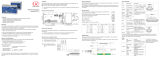
Analog Output
Analog outputs can either be used for distance or thickness measurements. Only one type of
measurement can be transmitted at any given time.
The analog output has a resolution of 16 bit. Either the voltage or the current output on the control-
ler can be used at any given time.
Start of measuring
range
End of measuring
range
10 V
11.4 V
0 V
Analog
output
LED “Range”
Standard characteristic
Error
Error
Target
Target in measuring range
Assembly Instructions
confocalDT 2461
confocalDT 2471LED
Functions
- Distance measurement against reflecting (mirroring and diffuse) surfaces
- Thickness measurement of transparent objects
- Triggering, synchronization and further functions
- Ethernet- or EtherCAT interface
- Measuring rate up to 25 kHz respectively 70 kHz
Warnings
Connect the power supply in accordance to the safety regulations for electrical equipment. The
power supply may not exceed the specified limits.
> Danger of injury, damage to or destruction of the system
Protect the optical fiber ends from dirt and contamination, protect the cables from damage.
> Failure of the measurement device
Avoid shock and vibration to the controller or the sensor.
> Damage to or destruction of the system
Notes on CE Identification
The following applies to the confocalDT 2461/2471LED system:
- EU directive 2014/30/EC
- EU directive 2011/65/EC, “RoHS“ category 9
The system satisfies the requirements of the standards
- EN 61000-6-3 / EN 61326-1 (Class B) Interference emission
- EN 61000-6-2 / EN 61326-1 Immunity to interference
Proper Environment
- Protection class IP 40 (Controller)
IP 40 - 64 (Sensor)
- Operating temperature
Controller: +5 ... +50 °C (+41 ... +122 °F)
Sensor: +5 ... +70 °C (+41 ... +158 °F)
- Storage temperature: -20 ... +70 °C (-4 ...+158 °F)
For further informations about the system read the instruction manual. You will find this online at:
www.micro-epsilon.com/download/manuals/man--confocalDT-2451-2461-2471--en.pdf or on the
delivered CD.
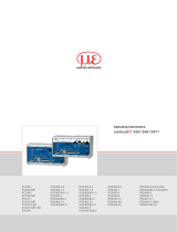
MICRO-EPSILON MESSTECHNIK
GmbH & Co. KG
Königbacher Str. 15 · 94496 Ortenburg
www.micro-epsilon.com
X9771238.03-A031068MSC
*X9771238.03-A03*

Quick Guide
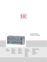
Structure of the Components
- Controller
- Power supply
- Laptop / PC + USB -> Ethernet adapter + Ethernet cable
- Sensor and clamp
Connect the components together and mount the sensor into the clamp.
Patch cable
Run
BECKHOFF EK1122
X1
X2
SyncIn / TrigIn
GND
Shield
SyncOut
GND
Error 1
GND
Shield
Error 2
GND
HLL
24 VDC
GND
Shield
U out
GND U
Shield
I out
GND I
Power
Digital I/O
RS422Encoder
Analog Out
confocalDT
Intensity >max
Intensity <min
Intensity ok
Out of range
Midrange
In range
Power On
Ethernet
Sensor
RS422
Encoder
Dark reference
STATUS
PS2020
230 VAC
PE
N L
PS2020
Sensor
Target
Commissioning
The controller is delivered ex factory with the IP address 169.254.168.150.
You can check the IP address of the controller, that are connected to a PC / network, with the
SensorFinder.exe program. You will find this program on the provided CD.
Now start the SensorFinder.exe and click on the button Find sensors.
Select the designated controller from the list.
Click the button Start browser to connect the controller with your default browser.
The start screen of the controller
software should be displayed in the
web browser now.
Select Measurement Program
Go to the menu Preferences > Measurement program.
Select displace Measurement as measurement program to be performed.
Select Sensor
Go to the menu Preferences > Sensor.
Select a sensor from the list. Confirm with Submit.
Perform Dark Reference
This adjustment is necessary after each sensor change; warm-up time controller about 30 min.
Cover the sensor with a piece of dark paper and press the Dark Reference button on con-
troller or the Start dark reference button on the Dark reference web page.
For dark referencing, no object must be within the measuring range, and no ambient or external
light must reach the sensor. Duration about 20 s. Alternatively, you can also perform the dark refer-
ence in the Video signal menu.
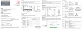
Place Target
Place the target in the midrange.
100 %
50
0
Sensor
SMR
SMR MMR EMR
Displacement
Signal
Target
Measuring range (MR)
The LED range on the front side of the controller shows the position of the target to the sensor.
Red flashing Dark signal acquisition in progress
Red No target, or target outside the measuring range
Yellow Target near the midrange
Green Target within the measuring range
Check Video Signal
Go to the Video signal menu and adjust any settings on the exposure mode, the measu-
ring rate and the detection threshold if applicable.
The recognition threshold should be as low as possible and preferably not be changed.
Menu Measurement
1
It is recommended, to set the scaling manually at first and not to select too fine.
Thickness Measurement
Go to the menu Preferences > Measurement program. Select the thickness
measurement program.
Differing from the previous steps the target material is to considered when measuring the thick-
ness.
Select a material from the database.
confocalDT 2461
Login
Measurement program
Sensor
Averaging/error handling
Zeroing/mastering
Exposure mode/measuring rate
Detection threshold
Material database
Switching outputs
Analog output
Digital interfaces
Output- data rate
Encoder inputs
Trigger mode
Synchronization
Home Preferences Measurement Video signal Help/Info
PS
Polystyrol,
a plastic
1.604079 1.590481 1.584949
PMMI
Polymethacryl
methylimid,
a plastic
1.534000 1.534000 1.534000
Material database
Preferences > Material database
Material name Description
Vacuum, Air Vacuum; air 1.000000 1.000000 1.000000
Fused Silica 1.463126 1.458464 1.456367
Refractive index
n
F
at 486 nm
Refractive index
n
D at
587 nm
Refractive index
n
C at
656 nm
Abbe value n
d
BK7 1.522380 1.516800 1.514320
PMMA
Acrylic glass
1.497761 1.491756 1.489200
Acrylic
Acrylic rosin, e.g
adhesive, lacquer
Crown glass
Quartz glass,
silica
1.497828 1.491668 1.488938
PC
Polycarbonat,
a plastic
1.599439 1.585470 1.579864
Save Setup
Save Settings
The current settings can be saved in the controller in one setup. Otherwise the settings are lost
when switching off.
confocalDT 2461
Settings loading / saving
Login
Measurement program
Sensor
Averaging/error handling
Zeroing/mastering
Exposure mode/measuring rate
Detection threshold
Material database
Switching outputs
Analog output
Digital interfaces
Output-data rate
Encoder inputs
Trigger mode
Synchronization
1
Home Preferences Measurement Video signal Help/Info
Preferences > Settings loading / saving
Setup no.:
Status: OK
Settings loading/saving
Manage setups on PC
Extras
Store settings in the controller permanently (otherwise the settings will be lost when turning off). Various
parameter sets can be stored. When turning on, the last stored parameter is loaded.
Save setup
Activate
Maintaining interface settings:
Maintain interface settings
If the checkbox is activated, the settings for language, password, analog output and network will kept.
Activate
By clicking this button, the selected setup file is loaded in the controller.
Save setup
Clicking this button saves the settings in the selected setup file.
Manage setups on PC Importing/exporting of setup and material settings between PC and controller.
Save Setup
Application flow saving:
Select a setup and click on the Save setup button.
When switching on, the parameter set (setup) is loaded, which is saved in the controller at last.
SMR = Start of measuring range
MMR = Midrange
EMR = End of measuring range
MR = Measuring range
1
/