MICRO-EPSILON confocalDT 2422 Assembly Instructions
- Type
- Assembly Instructions
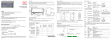
MICRO-EPSILON confocalDT 2422 is a powerful measurement device that offers precise and reliable distance and thickness measurements in various industrial applications. With its advanced confocal technology, it can measure on reflecting (mirroring and diffuse) surfaces and transparent objects with high accuracy. The device features an Ethernet or EtherCAT interface for easy integration into industrial networks, allowing for remote monitoring and control. Additionally, it provides synchronization and triggering capabilities for precise measurements in complex setups.
MICRO-EPSILON confocalDT 2422 is a powerful measurement device that offers precise and reliable distance and thickness measurements in various industrial applications. With its advanced confocal technology, it can measure on reflecting (mirroring and diffuse) surfaces and transparent objects with high accuracy. The device features an Ethernet or EtherCAT interface for easy integration into industrial networks, allowing for remote monitoring and control. Additionally, it provides synchronization and triggering capabilities for precise measurements in complex setups.


-
 1
1
-
 2
2


MICRO-EPSILON confocalDT 2422 Assembly Instructions
- Type
- Assembly Instructions
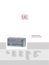
MICRO-EPSILON confocalDT 2422 is a powerful measurement device that offers precise and reliable distance and thickness measurements in various industrial applications. With its advanced confocal technology, it can measure on reflecting (mirroring and diffuse) surfaces and transparent objects with high accuracy. The device features an Ethernet or EtherCAT interface for easy integration into industrial networks, allowing for remote monitoring and control. Additionally, it provides synchronization and triggering capabilities for precise measurements in complex setups.
Ask a question and I''ll find the answer in the document
Finding information in a document is now easier with AI
Related papers
-
 MICRO-EPSILON confocalDT 2421 Assembly Instructions
-
 MICRO-EPSILON confocalDT 2421 / 2422 Quick Manual
-
 MICRO-EPSILON confocal DT 2421/2422 User manual
-
 MICRO-EPSILON confocalDT 2461 Assembly Instructions
-
 MICRO-EPSILON confocalDT 2451/2461/2471 User manual
-
 MICRO-EPSILON confocalDT 2411 EtherCAT Quick Manual
-
 MICRO-EPSILON confocalDT IFD2410 / 2411 / 2415 Operating instructions
-
 MICRO-EPSILON confocalDT 2471 Assembly Instructions
-
 MICRO-EPSILON software Disc Thickness Variation Measurement Owner's manual
-
MICRO-EPSILON colorCONTROL ACS7000 Assembly Instructions


