Page is loading ...

IFD2410-1
IFD2410-3
IFD2410-6
IFD2411-1
IFD2411-2
IFD2411/90-2
IFD2411-3
IFD2411-6
IFD2415-1
IFD2415-3
IFD2415-10
Operating Instructions
confocalDT IFD2410/2411/2415

Confocal chromatic distance and thickness measurement
MICRO-EPSILON
MESSTECHNIK
GmbH & Co. KG
Koenigbacher Str. 15
94496 Ortenburg/Germany
Tel. +49 (0) 8542 / 168-0
Fax +49 (0) 8542 / 168-90
e-mail [email protected]
www.micro-epsilon.com
confocalDT 2410
confocalDT 2411
confocalDT 2415
EtherCAT® is registered trademark and patented technology, licensed by
Beckhoff Automation GmbH, Germany.

confocalDT IFD2410/2411/2415
Contents
1. Safety ........................................................................................................................................ 9
1.1 Symbols Used ................................................................................................................................................. 9
1.2 Warnings .......................................................................................................................................................... 9
1.3 Notes on Product Marking............................................................................................................................. 10
1.3.1 Notes on CE Marking ................................................................................................................... 10
1.3.2 Notes on UKCA Marking .............................................................................................................. 10
1.4 Intended Use ................................................................................................................................................. 10
1.5 Proper Environment ....................................................................................................................................... 10
2. Functional Principle, Technical Data ..................................................................................... 11
2.1 Short Description ........................................................................................................................................... 11
2.2 Measuring Principle ....................................................................................................................................... 11
2.3 Term Definitions, Glossary ............................................................................................................................. 12
2.4 Technical Data for confocalDT IFD2410/2415 ............................................................................................... 13
2.5 Technical Data confocalDT IFD2411 ............................................................................................................. 14
3. Delivery ................................................................................................................................... 15
3.1 Scope of Delivery confocalDT IFD2410/2415 ............................................................................................... 15
3.2 Scope of Delivery confocalDT IFD2411 ........................................................................................................ 15
3.3 Storage .......................................................................................................................................................... 15
4. Mounting ................................................................................................................................. 16
4.1 Preliminary Remarks ...................................................................................................................................... 16
4.2 confocalDT IFD2410/2415 ............................................................................................................................. 16
4.2.1 Circumferential Clamping ............................................................................................................. 16
4.2.2 Direct Screw Connection.............................................................................................................. 17
4.2.3 Electrical Connections, Pin Assignment ...................................................................................... 18
4.2.4 Grounding Concept, Shielding .................................................................................................... 19
4.2.5 Supply Voltage (Power) ................................................................................................................ 19
4.2.6 RS422 ........................................................................................................................................... 20
4.2.7 Ethernet, EtherCAT ....................................................................................................................... 20
4.2.8 Analog Output .............................................................................................................................. 21
4.2.9 Multifunction inputs ...................................................................................................................... 21
4.2.10 Switching Outputs (digital I/O) ..................................................................................................... 22
4.2.11 Synchronization (Inputs/Outputs) ................................................................................................ 23
4.2.11.1 General ...................................................................................................................... 23
4.2.11.2 Internal Synchronization ........................................................................................... 23
4.2.11.3 External Synchronization .......................................................................................... 24
4.2.12 Triggering ...................................................................................................................................... 25
4.2.12.1 General ...................................................................................................................... 25
4.2.12.2 Triggering with Multifunction Input ........................................................................... 25
4.2.12.3 Triggering with Synchronization Input ...................................................................... 25
4.2.12.4 Triggering with Input Encoder 1 ............................................................................... 25
4.2.13 Encoder Inputs ............................................................................................................................. 26
4.3 confocalDT 2411 ............................................................................................................................................ 27
4.3.1 IFC2411 Controller ....................................................................................................................... 27
4.3.2 Sensor Cable, Optical Fiber ......................................................................................................... 27
4.3.3 Dimensional Drawing of Sensors ................................................................................................. 29
4.3.4 Fastening, Mounting Adapter ....................................................................................................... 29
4.3.4.1 General ...................................................................................................................... 29
4.3.4.2 Circumferential Clamping ......................................................................................... 29
4.3.5 Electrical Connections, Pin Assignment ...................................................................................... 31
4.3.6 Grounding Concept, Shielding .................................................................................................... 31
4.3.7 Supply Voltage (Power) ................................................................................................................ 32
4.3.8 RS422 ........................................................................................................................................... 32
4.3.9 Ethernet, EtherCAT ....................................................................................................................... 32
4.3.10 Analog Output .............................................................................................................................. 33
4.3.11 Multifunction Input ........................................................................................................................ 33
4.3.12 Synchronization (Inputs/Outputs) ................................................................................................ 34
4.3.12.1 General ...................................................................................................................... 34
4.3.12.2 Internal Synchronization ........................................................................................... 34
4.3.12.3 External Synchronization Controller ......................................................................... 35
4.3.13 Triggering ...................................................................................................................................... 36
4.3.13.1 General ...................................................................................................................... 36
4.3.13.2 Triggering with Multifunction Input ........................................................................... 36
4.3.13.3 Triggering with Synchronization Input ...................................................................... 36
4.3.13.4 Triggering with Input Encoder 1 ............................................................................... 37
4.3.14 Encoder Input ............................................................................................................................... 37
4.3.15 Handling of the Plug-In Screw Terminals ..................................................................................... 37
4.3.16 Dark Correction IFD2415 .............................................................................................................. 37
4.4 LEDs ............................................................................................................................................................... 38
4.5 Correct and Multifunction Key ....................................................................................................................... 38
5. Commissioning ...................................................................................................................... 39
5.1 Communication Options ................................................................................................................................ 39
5.2 Access via Web Interface .............................................................................................................................. 40
5.3 Positioning the Target .................................................................................................................................... 41
5.4 Select Sensor ................................................................................................................................................. 41
5.5 Presets, Setups, Measurement Configuration Selection .............................................................................. 42
5.6 Video Signal ................................................................................................................................................... 43

confocalDT IFD2410/2411/2415
5.7 Signal Quality ................................................................................................................................................ 44
5.8 Distance Measurement with Website Display ............................................................................................... 45
5.9 Save/Load Settings ........................................................................................................................................ 47
5.10 Dark Correction.............................................................................................................................................. 49
6. Set Sensor Parameters, Web Interface ................................................................................. 51
6.1 Inputs ............................................................................................................................................................. 51
6.1.1 Synchronization ............................................................................................................................ 51
6.1.2 Encoder Inputs ............................................................................................................................ 51
6.1.2.1 Overview, Menu ......................................................................................................... 51
6.1.2.2 Number of Encoders ................................................................................................. 51
6.1.2.3 Interpolation ............................................................................................................. 52
6.1.2.4 Maximum Value ......................................................................................................... 52
6.1.2.5 Effect of Reference Track .......................................................................................... 52
6.1.2.6 Set to Value ............................................................................................................... 52
6.1.2.7 Reset Reference Marker ........................................................................................... 52
6.1.3 Level Function Inputs ................................................................................................................... 53
6.1.4 Terminating Resistor ..................................................................................................................... 53
6.2 Data Recording .............................................................................................................................................. 54
6.2.1 Measuring Rate ............................................................................................................................ 54
6.2.2 Triggering Data Acquisition .......................................................................................................... 55
6.2.2.1 General ...................................................................................................................... 55
6.2.2.2 Triggering Measured Value Acquisition ................................................................... 55
6.2.2.3 Trigger Time Difference ............................................................................................. 56
6.2.3 Reset Counter ............................................................................................................................... 56
6.2.4 Range of Interest Masking ........................................................................................................... 56
6.2.5 Exposure Mode ............................................................................................................................ 57
6.2.6 Peak Separation .......................................................................................................................... 58
6.2.6.1 Peak Modulation ....................................................................................................... 58
6.2.6.2 Detection Threshold ................................................................................................. 58
6.2.7 Number of Peaks, Peak Selection ................................................................................................ 59
6.2.8 Material Selection ......................................................................................................................... 60
6.3 Signal Processing, Calculation ...................................................................................................................... 61
6.3.1 Data Source, Parameters, Calculation Programs ........................................................................ 61
6.3.2 Definitions ..................................................................................................................................... 62
6.3.3 Measurement Averaging .............................................................................................................. 63
6.4 Post-Processing ............................................................................................................................................. 66
6.4.1 Zeroing, Mastering ....................................................................................................................... 66
6.4.2 Statistics ....................................................................................................................................... 68
6.4.3 Data Reduction, Output Data Rate ............................................................................................... 69
6.4.4 Error Handling (Hold Last Value) ................................................................................................. 69
6.5 Outputs .......................................................................................................................................................... 70
6.5.1 Interface RS422 ............................................................................................................................ 70
6.5.2 Ethernet Setup Mode ................................................................................................................... 70
6.5.3 RS422 ........................................................................................................................................... 70
6.5.4 Analog Output .............................................................................................................................. 71
6.5.4.1 Calculating Measured Value from Current Output ................................................... 71
6.5.4.2 Calculation measured value from Voltage Output ................................................... 72
6.5.5 Data Output .................................................................................................................................. 72
6.6 System Settings ............................................................................................................................................. 73
6.6.1 Web Interface Unit ........................................................................................................................ 73
6.6.2 Key Lock ....................................................................................................................................... 73
6.6.3 Loading and Saving ..................................................................................................................... 73
6.6.4 Access Authorization .................................................................................................................... 73
6.6.5 Reset System ................................................................................................................................ 74
6.6.6 Light Source ................................................................................................................................. 74
6.6.7 Boot Mode .................................................................................................................................... 74
7. Thickness Measurement, One-Sided, Transparent Target ................................................... 75
7.1 Requirement .................................................................................................................................................. 75
7.2 Preset ............................................................................................................................................................. 75
7.3 Material Selection .......................................................................................................................................... 75
7.4 Video Signal ................................................................................................................................................... 76
7.5 Signal Processing .......................................................................................................................................... 76
7.6 Measurement Chart ....................................................................................................................................... 77
8. EtherCAT Documentation ...................................................................................................... 78
8.1 General .......................................................................................................................................................... 78
8.2 Introduction .................................................................................................................................................... 78
8.2.1 Structure of EtherCAT® Frames .................................................................................................. 78
8.2.2 EtherCAT® Services ..................................................................................................................... 78
8.2.3 Addressing and FMMUs ............................................................................................................... 79
8.2.4 Sync Manager .............................................................................................................................. 79
8.2.5 EtherCAT State Machine .............................................................................................................. 79
8.2.6 CANopen over EtherCAT.............................................................................................................. 80
8.2.7 Process Data PDO Mapping ........................................................................................................ 80
8.2.8 Service Data SDO Service ............................................................................................................ 80
8.3 CoE – Object Directory .................................................................................................................................. 81
8.3.1 Communication Specific Standard Objects ................................................................................. 81
8.3.1.1 Overview ................................................................................................................... 81
8.3.1.2 Object 1001h: Device Type ....................................................................................... 81
8.3.1.3 Object 1008h: Manufacturer Device Name .............................................................. 81
8.3.1.4 Object 1009h: Hardware Version .............................................................................. 81
8.3.1.5 Object 100Ah: Software Version ............................................................................... 81

confocalDT IFD2410/2411/2415
8.3.1.6 Object 1018h: Device Identification .......................................................................... 81
8.3.1.7 TxPDO Mapping IFD2410, 2411 ............................................................................... 82
8.3.1.8 TxPDO Mapping IFD2415 ......................................................................................... 91
8.3.1.9 Example of TxPDO Mapping .................................................................................. 104
8.3.1.10 Object 1C00h: Synchronous Manager Type .......................................................... 105
8.3.1.11 Object 1C12h: RxPDO Assign ................................................................................ 105
8.3.1.12 Object 1C13h: TxPDO Assign ................................................................................ 105
8.3.1.13 Object 1C32h: Sync Manager Output Parameters ................................................. 106
8.3.1.14 Object 1C33h: Sync Manager Input Parameters ................................................... 106
8.3.2 Manufacturer Specific Objects ................................................................................................... 107
8.3.2.1 Overview ................................................................................................................. 107
8.3.2.2 Object 3001h: User Level ....................................................................................... 108
8.3.2.3 Object 3005h: Information on the IFD241x (further) .............................................. 108
8.3.2.4 Object 3011h: Correction, Channel 1 ..................................................................... 108
8.3.2.5 Object 3020h: Load, Save, Factory Setting ............................................................ 109
8.3.2.6 Object 3021h: Preset .............................................................................................. 109
8.3.2.7 Object 3022h: Measurement Settings .................................................................... 109
8.3.2.8 Object 303Fh: Error IFD241x .................................................................................. 110
8.3.2.9 Object 3101h: Reset ............................................................................................... 110
8.3.2.10 Object 3105h: Factory Settings .............................................................................. 110
8.3.2.11 Object 3107h: Reset Counter ................................................................................. 110
8.3.2.12 Object 3133h: LED Light Source Channel 1 .......................................................... 110
8.3.2.13 Object 3150h: Error IFD241x Channel 1 ................................................................ 110
8.3.2.14 Object 3152h: Sensor Selection Channel 1 ........................................................... 111
8.3.2.15 Object 3153h: Sensor Table ................................................................................... 111
8.3.2.16 Object 3156h: Multilayer Options for Channel 1 .................................................... 111
8.3.2.17 Object 3161h: Peak Selection Channel 1 ............................................................... 111
8.3.2.18 Object 3162h: Peak Options Channel 1 ................................................................. 112
8.3.2.19 Object 31B0h: Digital Interfaces ............................................................................. 112
8.3.2.20 Object 31B1h: Interface Selection .......................................................................... 112
8.3.2.21 Object 31B2h: Error Handling ................................................................................ 112
8.3.2.22 Object 31B3h: Data Reduction ............................................................................... 112
8.3.2.23 Object 31D0h: Analog Output ................................................................................ 113
8.3.2.24 Object 31F3h: Switching Output 1 ......................................................................... 114
8.3.2.25 Object 31F5h: RS422 Output ................................................................................. 115
8.3.2.26 Object 3250h: Exposure Mode Channel 1 ............................................................. 115
8.3.2.27 Object 3251h: Measuring Rate ............................................................................... 115
8.3.2.28 Object 34A0h: Keylock ........................................................................................... 115
8.3.2.29 Object 35A0h: Encoder .......................................................................................... 116
8.3.2.30 Object 35B0 Triggering ........................................................................................... 116
8.3.2.31 Object 35B1 Synchronization ................................................................................. 117
8.3.2.32 Object 3711h: Range of Interest Masking Channel 1 ............................................ 117
8.3.2.33 Object 3800h: Material Information ........................................................................ 117
8.3.2.34 Object 3802h: Edit Material Table ........................................................................... 118
8.3.2.35 Object 3803h: Existing Materials ............................................................................ 118
8.3.2.36 Object 3804h: Select Material for Channel 1 .......................................................... 118
8.3.2.37 Object 3A00h: Mastering, Zeroing .......................................................................... 118
8.3.2.38 Object 3A10h: Statistics .......................................................................................... 119
8.3.2.39 Object 3C00h: Measured Value Calculation Channel 1 ......................................... 120
8.3.2.40 Object 3CBFh: Sys Signals .................................................................................... 121
8.3.2.41 Object 3E00: User Signals ...................................................................................... 121
8.4 Mappable Objects – Process Data .............................................................................................................. 122
8.4.1 Object 6000, 6001: Distance Value ............................................................................................ 122
8.4.2 Object 6010, 6011: Intensity ....................................................................................................... 122
8.4.3 Object 6030: Exposure Time ...................................................................................................... 123
8.4.4 Object 6050, 6051, 6052: Encoder ............................................................................................ 123
8.4.5 Object 6060: Peak Symmetry..................................................................................................... 123
8.4.6 Object 7000: Measured Value Counter ...................................................................................... 124
8.4.7 Object 7001: Timestamp ............................................................................................................ 124
8.4.8 Object 7002: Measuring Rate ..................................................................................................... 124
8.4.9 Object 7C00: Calculated Process Data ..................................................................................... 125
8.5 Error Codes for SDO Services ..................................................................................................................... 125
8.6 Oversampling............................................................................................................................................... 126
8.7 Calculation ................................................................................................................................................... 128
8.7.1 Setting a Filter ............................................................................................................................. 128
8.7.2 Thickness Calculation ................................................................................................................ 128
8.8 Operational Modes ...................................................................................................................................... 129
8.8.1 Free Run ..................................................................................................................................... 129
8.8.2 Distributed Clocks SYNC0 Synchronization .............................................................................. 129
8.8.3 SM2/SM3 Synchronization ......................................................................................................... 129
8.9 Update ......................................................................................................................................................... 129
8.9.1 Update via FoE ........................................................................................................................... 129
8.9.2 Update via EoE ........................................................................................................................... 129
8.10 Meaning of LEDs in EtherCAT Operation .................................................................................................... 130
8.11 EtherCAT Configuration with the Beckhoff TwinCAT© Manager ................................................................ 131
9. Error, Repair ......................................................................................................................... 133
9.1 Web Interface Communication .................................................................................................................... 133
9.2 Changing the Sensor Cable on the Sensors .............................................................................................. 133
9.3 Replacing the Protective Glass on the Sensors .......................................................................................... 133
10. Software Support with MEDAQLib ...................................................................................... 134
11. Disclaimer ............................................................................................................................ 134

confocalDT IFD2410/2411/2415
12. Service, Repair .................................................................................................................... 135
13. Decommissioning, Disposal ................................................................................................ 136
Appendix ............................................................................................................................... 137
A 1 Optional accessories, services ........................................................................................... 137
A 1.1 Optional accessories confocalDT IFD2410/2415 ........................................................................................ 137
A 1.2 Optional Accessories confocalDT IFD2411 ................................................................................................ 137
A 1.3 Services ....................................................................................................................................................... 137
A 2 Factory Settings ................................................................................................................... 138
A 2.1 confocalDT IFD2410/2415 ........................................................................................................................... 138
A 2.2 confocalDT IFD2411 .................................................................................................................................... 138
A 3 Adjustable Mounting Adapter JMA-xx ................................................................................. 139
A 3.1 Functions .................................................................................................................................................... 139
A 3.2 Sensor Mounting, Compatibility .................................................................................................................. 139
A 3.3 Mounting ...................................................................................................................................................... 139
A 3.4 Dimensional Drawing of Mounting Adapter ................................................................................................ 139
A 3.5 Perpendicular Alignment of Sensor............................................................................................................. 140
A 4 Cleaning Optical Components ............................................................................................ 141
A 4.1 Contamination ............................................................................................................................................. 141
A 4.2 Tools and Cleaning Agents ......................................................................................................................... 142
A 4.3 Sensor Protective Glass .............................................................................................................................. 142
A 4.4 Interface between Controller and Sensor Cable ......................................................................................... 143
A 4.5 Interface between Sensor Cable and Sensor ............................................................................................. 144
A 4.6 Preventive Protection ................................................................................................................................... 144
A 5 ASCII Communication with Controller ................................................................................ 145
A 5.1 General ........................................................................................................................................................ 145
A 5.2 Commands Overview .................................................................................................................................. 145
A 5.3 General Commands .................................................................................................................................... 148
A 5.3.1 General ...................................................................................................................................... 148
A 5.3.1.1 Help ........................................................................................................................ 148
A 5.3.1.2 Controller Information ............................................................................................. 148
A 5.3.1.3 Reply type ............................................................................................................... 148
A 5.3.1.4 Parameter Overview ............................................................................................... 148
A 5.3.1.5 Synchronization ..................................................................................................... 149
A 5.3.1.6 Termination Resistor at Sync/Trig ........................................................................... 149
A 5.3.1.7 Boot Sensor ........................................................................................................... 149
A 5.3.1.8 Reset Counter ......................................................................................................... 149
A 5.3.2 User level .................................................................................................................................... 150
A 5.3.2.1 Change User Level ................................................................................................ 150
A 5.3.2.2 Switch to User Level .............................................................................................. 150
A 5.3.2.3 User Level Query ................................................................................................... 150
A 5.3.2.4 Set Standard User .................................................................................................. 150
A 5.3.2.5 Change Password .................................................................................................. 150
A 5.3.3 Level of Multifunction Inputs....................................................................................................... 150
A 5.3.4 Sensor ........................................................................................................................................ 151
A 5.3.4.1 Information on Calibration Tables ........................................................................... 151
A 5.3.4.2 Sensor Information ................................................................................................. 151
A 5.3.4.3 Dark Correction ....................................................................................................... 151
A 5.3.4.4 LED .......................................................................................................................... 151
A 5.3.4.5 Control Input Measurement Light Source .............................................................. 151
A 5.3.5 Triggering .................................................................................................................................... 152
A 5.3.5.1 Select Trigger Source ............................................................................................. 152
A 5.3.5.2 Output of Triggered Values, with/without Averaging .............................................. 152
A 5.3.5.3 Trigger Type ............................................................................................................ 152
A 5.3.5.4 Active Level of Trigger Input ................................................................................... 152
A 5.3.5.5 Software Trigger Pulse ............................................................................................ 152
A 5.3.5.6 Number of Measured Values to be Output ............................................................. 152
A 5.3.5.7 Level Section Trigger Input TrigIn ........................................................................... 153
A 5.3.5.8 Step Size Encoder Triggering ................................................................................. 153
A 5.3.5.9 Minimum Encoder Triggering ................................................................................. 153
A 5.3.5.10 Maximum Encoder Triggering ................................................................................ 153
A 5.3.6 Encoder ...................................................................................................................................... 153
A 5.3.6.1 Number of Available Encoders ............................................................................... 153
A 5.3.6.2 Encoder Interpolation Depth .................................................................................. 153
A 5.3.6.3 Effect of Reference Track ........................................................................................ 153
A 5.3.6.4 Encoder value ......................................................................................................... 154
A 5.3.6.5 Set Encoder Value via Software ............................................................................. 154
A 5.3.6.6 Reset Detection of First Reference Marker ............................................................. 154
A 5.3.6.7 Maximum Encoder Value ........................................................................................ 154
A 5.3.6.8 Number of Active Encoders .................................................................................... 154
A 5.3.7 Setting the RS422 Baud Rate ..................................................................................................... 155
A 5.3.8 Parameter Management, Load/Save Settings ........................................................................... 156
A 5.3.8.1 Load / Save Connection Settings ........................................................................... 156
A 5.3.8.2 Show Changed Parameters .................................................................................... 156
A 5.3.8.3 Export Parameter Sets to PC .................................................................................. 156
A 5.3.8.4 Import Parameter Sets from PC .............................................................................. 156
A 5.3.8.5 Factory Settings ...................................................................................................... 156
A 5.3.8.6 Editing, Storing, Displaying, Deleting Measurement Settings ............................... 157

confocalDT IFD2410/2411/2415
A 5.3.9 Measurement .............................................................................................................................. 157
A 5.3.9.1 Peak count .............................................................................................................. 157
A 5.3.9.2 Peak Selection ........................................................................................................ 157
A 5.3.9.3 Number of Peaks and Switching Refractivity Correction On/Off ............................ 158
A 5.3.9.4 Exposure Mode ....................................................................................................... 158
A 5.3.9.5 Measuring rate ........................................................................................................ 158
A 5.3.9.6 Exposure Time ........................................................................................................ 158
A 5.3.9.7 Range of Interest (ROI) ........................................................................................... 158
A 5.3.9.8 Minimum Threshold Peak Detection ...................................................................... 158
A 5.3.9.9 Peak Modulation ..................................................................................................... 159
A 5.3.10 Material Database ....................................................................................................................... 159
A 5.3.10.1 Material Table .......................................................................................................... 159
A 5.3.10.2 Select Material......................................................................................................... 159
A 5.3.10.3 Show Material Property........................................................................................... 159
A 5.3.10.4 Existing Material in Controller ................................................................................. 159
A 5.3.10.5 Protected Materials in Controller ............................................................................ 159
A 5.3.10.6 Edit Material Table ................................................................................................... 160
A 5.3.10.7 Delete a Material ..................................................................................................... 160
A 5.3.10.8 Add Material ............................................................................................................ 160
A 5.3.11 Edit measured value ................................................................................................................... 160
A 5.3.11.1 Statistical Calculations ............................................................................................ 160
A 5.3.11.2 List of Statistics Signals .......................................................................................... 160
A 5.3.11.3 Selection of Statistics Signal .................................................................................. 161
A 5.3.11.4 List of Possible Statistics Signals to Select ............................................................ 161
A 5.3.11.5 List of Possible Signals to be Parameterized ......................................................... 161
A 5.3.11.6 Parameterization of Master Signals ........................................................................ 161
A 5.3.11.7 List of Possible Signals for Mastering ..................................................................... 161
A 5.3.11.8 Mastering / Zeroing ................................................................................................ 161
A 5.3.11.9 Signal for Mastering with External Source ............................................................. 162
A 5.3.11.10 Mastering with External Source .............................................................................. 162
A 5.3.11.11 Example of Mastering ............................................................................................ 162
A 5.3.11.12 Calculation in channel ........................................................................................... 164
A 5.3.11.13 List of Possible Calculation Signals ........................................................................ 164
A 5.3.11.14 Two-Point Scaling Data Outputs ............................................................................. 164
A 5.3.12 Data Output ................................................................................................................................ 165
A 5.3.12.1 Digital Output Selection .......................................................................................... 165
A 5.3.12.2 Output Data Rate .................................................................................................... 165
A 5.3.12.3 Reduction Counter for Output of measured values ............................................... 165
A 5.3.12.4 Error Handling ......................................................................................................... 165
A 5.3.13 Selection of Measured Values to be Output .............................................................................. 166
A 5.3.13.1 General .................................................................................................................... 166
A 5.3.13.2 Data Selection for RS422 ........................................................................................ 166
A 5.3.13.3 List of Possible Signals for RS422 .......................................................................... 166
A 5.3.13.4 List of Selected Signals, Sequence via Rs422 ....................................................... 166
A 5.3.14 Switching Outputs ...................................................................................................................... 166
A 5.3.14.1 General .................................................................................................................... 166
A 5.3.14.2 Error - Switching Outputs ....................................................................................... 166
A 5.3.14.3 List of Possible Signals for Error Output ................................................................ 166
A 5.3.14.4 Set Signal to be Evaluated ..................................................................................... 166
A 5.3.14.5 Set Limit Values ....................................................................................................... 167
A 5.3.14.6 Set Value ................................................................................................................. 167
A 5.3.14.7 Switching Behavior of Error Outputs ...................................................................... 167
A 5.3.14.8 Switching Hysteresis of Error Outputs ................................................................... 167
A 5.3.15 Analog Output ............................................................................................................................ 167
A 5.3.15.1 Data Selection ......................................................................................................... 167
A 5.3.15.2 List of Possible Signals for Analog Output ............................................................. 167
A 5.3.15.3 Output Range .......................................................................................................... 167
A 5.3.15.4 Set Scaling for DAC ................................................................................................ 168
A 5.3.15.5 Set Scaling Range .................................................................................................. 168
A 5.3.16 System Settings .......................................................................................................................... 168
A 5.3.16.1 Key Lock.................................................................................................................. 168
A 5.3.16.2 Switch EtherCAT to Ethernet Setup Mode ............................................................. 168
A 5.4 Measured Value Format............................................................................................................................... 169
A 5.4.1 Structure ..................................................................................................................................... 169
A 5.4.2 Video Signal ............................................................................................................................... 169
A 5.4.3 Exposure Time ............................................................................................................................ 169
A 5.4.4 Encoder ...................................................................................................................................... 169
A 5.4.5 Measured Value Counter ............................................................................................................ 170
A 5.4.6 Timestamp .................................................................................................................................. 170
A 5.4.7 Measuring Data (Distances and Intensities) .............................................................................. 170
A 5.4.8 Trigger Time Difference .............................................................................................................. 170
A 5.4.9 Differences (thicknesses) ........................................................................................................... 170
A 5.4.10 Statistical Values ......................................................................................................................... 170
A 5.4.11 Peak Symmetry .......................................................................................................................... 170
A 5.5 Measuring Data Formats ............................................................................................................................. 171
A 5.5.1 Data Format RS422 Interface ..................................................................................................... 171
A 5.5.1.1 Video Data ............................................................................................................... 171
A 5.5.1.2 Measured Values .................................................................................................... 171
A 5.6 Warning and Error Messages ...................................................................................................................... 173

confocalDT IFD2410/2411/2415
A 6 Switch between EtherCAT and Ethernet Setup Mode ........................................................ 175
A 7 Switching between Ethernet Setup Mode and EtherCAT ................................................... 175
A 8 Telnet ..................................................................................................................................... 176
A 8.1 General ........................................................................................................................................................ 176
A 8.2 Establishing the Connection ....................................................................................................................... 176
A 8.3 Help on a Command ................................................................................................................................... 177
A 8.4 Error Messages ............................................................................................................................................ 177

Page 9
Safety
confocalDT IFD2410/2411/2415
1. Safety
System operation assumes knowledge of the operating instructions.
1.1 Symbols Used
The following symbols are used in these operating instructions:
CAUTION Indicates a hazardous situation which, if not avoided, may result in minor or moderate injury.
NOTICE
Indicates a situation that may result in property damage if not avoided.
Indicates a user action.
iIndicates a tip for users.
Measurement
Indicates hardware or a software button/menu.
1.2 Warnings
CAUTION Connect the power supply and the display/output device according to the safety regulations for elec-
trical equipment.
> Risk of injury
> Damage to or destruction of the controller
The surface of the sensors or controller heats up to a temperature of over 50°C when all interfaces
are used.
> Risk of injury
NOTICE
The supply voltage must not exceed the specified limits.
> Damage to or destruction of the controller
Avoid shocks and impacts to the controller and the sensor.
> Damage to or destruction of the components
Never fold the optical fiber and do not bend it in tight radii.
> Damage to or destruction of the optical fiber, failure of measuring device
Protect the ends of the optical fiber against contamination (use protective caps).
> Incorrect measurement
> Failure of the measuring device
Protect the cables against damage.
> Failure of the measuring device

Page 10
Safety
confocalDT IFD2410/2411/2415
1.3 Notes on Product Marking
1.3.1 Notes on CE Marking
Please note the following for the confocalDT IFD2410/2411/2415 measuring system:
-EU Directive 2014/30/EU
-EU Directive 2011/65/EU
Products which carry the CE mark satisfy the requirements of the EU directives cited and the relevant applicable har-
monized European standards (EN). The measuring system is designed for use in industrial and home applications and
meets the requirements.
The EU Declaration of Conformity is available to the responsible authorities according to EU Directive, Article 10.
1.3.2 Notes on UKCA Marking
Please note the following for the confocalDT IFD2410/2411/2415 measuring system:
-SI 2016 No. 1091:2016-11-16 The Electromagnetic Compatibility Regulations 2016
-SI 2012 No. 3032:2012-12-07 The Restriction of the Use of Certain Hazardous Substances in Electrical and Electronic
Equipment Regulations 2012
Products which bear the CE mark meet the requirements of the EU directives cited and the relevant applicable harmo-
nized European standards. The measuring system is designed for use in industrial environments.
The UKCA marking and the technical documentation are available to the responsible authorities according to UKCA
directives.
1.4 Intended Use
-The measuring system confocalDT IFD2410/2411/2415 is designed for use in an industrial environment. It is used for
Displacement, distance, movement and thickness measurement,
measuring the position of parts or machine components
-The measuring system must only be operated within the limits specified in the technical data see Chap. 2.4.
The measuring system must only be used in such a way that no persons are endangered or machines are dam-
aged in the event of malfunction or total failure of the sensor.
Take additional precautions for safety and damage prevention in case of safety-related applications.
1.5 Proper Environment
confocalDT IFD2410/2415 confocalDT IFD2411
Sensor Controller
Protection class IP64, front side IP64, front side IP40
Operating temperature range +5 ... +50 °C +5 ... +70 °C +5 ... +50 °C
Storage temperature range -20 ... +70 °C
Humidity 5 ... 95% (non-condensing)
Ambient pressure: Atmospheric pressure
Shock (DIN EN 60068-2-27) 15 g/6 ms on XY axis, 1000 shocks each
Vibration (DIN EN 60068-2-6) 2 g / 20 ... 500 Hz on XY axis, 10 cycles each
EMC As per EN 61000-6-3 / EN 61326-1 (Class B) Emitted interference; EN 61000-6-2
/ EN 61326-1 Immunity to interference

Page 11
Functional Principle, Technical Data
confocalDT IFD2410/2411/2415
2. Functional Principle, Technical Data
2.1 Short Description
The measuring systems consists of:
Controller Controller
(IFC2411)
(IFD2410-x,
IFD2415-x)
Optical fiber (sensor
cable)
Sensor
Sensor
(IFSxxx)
confocalDT IFD2410/2415 confocalDT IFD2411
With the IFD2410/2415, the sensor and
controller form a single unit. It is not
possible to exchange the sensor.
IFC2411 series controllers can be operated with
different sensors. The calibration tables of the sen-
sors required to do so need to be saved in the con-
troller.
The measuring systems use a white LED as an internal light source.
The IFSxxx sensor is passive, since it does not contain any heat sources or moving parts. This prevents heat expansion,
which makes for a highly accurate measurement process.
The controller converts the light signals received from the sensor with a spectrometer, calculates distance or thickness
values with the integrated signal processor (CPU) and transfers the measured data via the interfaces or analog output.
2.2 Measuring Principle
Polychromatic light (white light) is beamed through the sensor onto the target surface. The sensor’s lenses are designed
to focus each wavelength of light used at a specific distance through controlled chromatic aberrations. The light reflected
by the target surface is received by the sensor on the way back and directed to the controller. This is followed by spectral
analysis and the calculation of distances using calibration data saved in the controller.
i The sensor and controller form a single unit, as the linearization table of the sensor is saved in the controller.
This unique measuring principle enables high-precision measurement of applications. It can capture both diffuse and
reflective surfaces. With transparent layer materials, a direct thickness measurement can be carried out in addition to the
displacement measurement. The transmitter and receiver are arranged on one axis to prevent shadowing.
Excellent resolution and small light spot diameter make it possible to measure surface structures. However, it should be
noted that deviations in measured values can occur as soon as the structure is in the order of magnitude of the light spot
diameter or the permissible tilt is exceeded, for example at groove walls.

Page 12
Functional Principle, Technical Data
confocalDT IFD2410/2411/2415
2.3 Term Definitions, Glossary
SMR Start of measuring range. A start of measuring range (SMR) must be kept between each sensor and the target.
Minimal distance between the front sensor face and the target.
MMR Mid of measuring range
EMR End of measuring range (start of measuring range + measuring range)
Maximum distance between the front sensor face and the target.
MB Measuring range
100 %
50
0
Sensor SMR Target
Measuring range (MR)
SMR MMR EMR
Displacement
Signal
Fig. 1 Measuring range and output measuring system
Minimum target thickness see Chapter Technical Data
Maximum target thickness Sensor measuring range x refractive index of target

Page 13
Functional Principle, Technical Data
confocalDT IFD2410/2411/2415
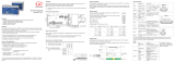
2.4 Technical Data for confocalDT IFD2410/2415
Model IFD2410-1 IFD2410-3 IFD2410-6 IFD2415-1 IFD2415-3 IFD2415-10
Measuring
range
Distance 1.0 mm 3.0 mm 6.0 mm 1.0 mm 3.0 mm 10.0 mm
Minimum thick-
ness 0.05 mm 0.15 mm 0.3 mm 0.05 mm 0.15 mm 0.5 mm
Start of mea-
suring range approx. approx. 15
mm
approx. 25
mm
approx. 35
mm
approx. 10
mm
approx. 20
mm
approx. 50
mm
Resolution Static 1 < 12 nm < 36 nm < 80 nm < 8 nm < 15 nm < 36 nm
dynamic 2 < 50 nm < 125 nm < 250 nm < 38 nm < 80 nm < 204 nm
Measuring rate Continuously adjustable from 100 Hz to 8 kHz Continuously adjustable from 100 Hz to 25 kHz
Linearity 3 Displacement and
distance mea-
surement
< ±0.5 µm < ±1.5 µm < ±3.0 µm < ±0.25 µm < ±0.75 µm < ±2.5 µm
Thickness mea-
surements < ±1.0 µm < ±3.0 µm < ±6.0 µm < ±0.5 µm < ±1.5 µm < ±5.0 µm
Multi-layer measurement - up to 5 layers
Light source Internal white LED
Permissible ambient light 30,000 lx
Light spot diameter 4 12 µm 18 µm 24 µm 8 µm 9 µm 16 µm
Measuring angle 5 ±25° ±19° ±10° ±30° ±24° ±17°
Numerical aperture (NA) 0.45 0.35 0.18 0.55 0.45 0.3
Target material Reflective, diffuse as well as transparent surfaces (e.g. glass)
Supply voltage 24 VDC ±10 %
Power consumption <5.3 W (24 V) <7 W (24 V)
Signal input 2 x encoders (A+, A-, B+, B-, Index)
2 x HTL/TTL multifunction input: Trigger in, slave in, zeroing, master, teach;
1 x RS422 synchronization input: Trigger in, sync in, master/slave, master/slave alternating
Digital interface EtherCAT / RS422 / (Ethernet for configuration)
Analog output 4 … 20 mA / 0 … 5 V / 0 ... 10 V (16 bit D/A converter)
Switching output Error1-Out, Error2-Out
Digital output Sync out
Connection 12-pin M12 connector for supply, encoder, EtherCAT, RS422 and synchronization
17-pin M12 connector for I/O analog and encoder
allows optional extension to 3 m / 6 m / 9 m / 15 m (see accessories for suitable connection
cables)
Mounting Radial clamping, threaded holes, mounting adapter (see accessories)
Temperature
range
Storage -20 ... +70 °C
Operation +5 ... +50 °C
Shock (DIN EN 60068-2-27) 15 g/6 ms on XY axis, 1000 shocks each
Vibration (DIN EN 60068-2-6) 2 g/20 … 500 Hz on XY axis, 10 cycles each
Protection class
(DIN EN 60529)
Sensor IP64, front side
Controller IP65
Material Aluminum housing, passively cooled
Weight approx. 490 g 490 g 490 g 500 g 600 g 800 g
Control and display elements Correct key: Interface selection,
two adjustable functions as well as reset to factory setting after 10 s;
4x color LED for Intensity, Range, RUN and ERR
All data based on constant ambient temperature (24 ± 2°C)
1) Averaged over 512 values, at 1 kHz, in mid of measuring range on test glass
2) RMS noise in relation to mid of measuring range (1 kHz)
3) Maximum deviation from reference system over the entire measuring range, measured on front surface of ND filter
4) In mid of measuring range
5) Maximum sensor tilt up to which a usable signal on a polished glass (n = 1.5) can be obtained at mid of measuring range, in which
the accuracy decreases towards the limit values

Page 14
Functional Principle, Technical Data
confocalDT IFD2410/2411/2415
2.5 Technical Data confocalDT IFD2411
Model IFD2411-1 IFD2411-2 IFD2411/90-2 IFD2411-3 IFD2411-6
Measuring range Distance 1.0 mm 2.0 mm 2.0 mm 3.0 mm 6.0 mm
Start of measuring
range approx. 15 mm 14 mm 9.6 mm 1 25 mm 35 mm
Resolution Static 2 < 12 nm < 40 nm < 40 nm < 40 nm < 80 nm
dynamic 3 < 50 nm < 125 nm < 125 nm < 125 nm < 250 nm
Measuring rate Continuously adjustable from 100 Hz to 8 kHz
Linearity 4 Distance < ±0.5 µm < ±1.0 µm < ±1.0 µm < ±1.5 µm < ±3.0 µm
Thickness < ±1.0 µm < ±2.0 µm < ±2.0 µm < ±3.0 µm < ±6.0 µm
Multi-layer measurement 1 layer
Light source Internal white LED
No. of characteristic curves Saves up to 10 characteristic curves of different sensors,
selection via table in the menu
Permissible ambient light 5 30,000 lx
Light spot diameter 12 µm 10 µm 10 µm 18 µm 24 µm
Measuring angle 6 ±25° ±12° ±12° ±19° ±10°
Numerical aperture (NA) 0.45 0.25 0.25 0.35 0.18
Minimum thickness 7 0.05 mm 0.1 mm 0.1 mm 0.15 mm 0.3 mm
Target material Reflective, diffuse as well as transparent surfaces (e.g. glass)
Synchronization yes
Supply voltage 24 VDC ±10 %
Power consumption <max. 7 W (24 V)
Signal input Sync-In / trig-In; 1 x encoder (A+, A-, B+, B-, Index)
Digital interface EtherCAT / RS422 / (Ethernet for configuration)
Analog output Current: 4 … 20 mA; current: 0 ... 5V & 0 … 10 V (16 bit D/A converter)
Digital output Sync-out
Connection
Optical Plug-in optical fiber via E2000 connector, length 2 m ... 50 m,
min. bending radius 30 mm
Electrical
3-pin supply terminal block;
5-pin I/O terminal block (max. cable length 30 m);
17-pin M12 connector for RS422, analog and encoder;
RJ45 connector for Ethernet (out) / EtherCAT (in/out) (max. cable length 100 m)
Mounting free-standing, DIN rail mounting
Temperature range Storage -20 ... +70 °C
Operation Sensor: +5 … +70 °C | Controller: +5 ... +50 °C
Shock (DIN-EN60068-2-27) 15 g/6 ms on XYZ axis, 1000 shocks each
Vibration (DIN EN 60068-2-6) 2 g/20 … 500 Hz on XYZ axis, 10 cycles each
Protection class
(DIN-EN60529)
Sensor IP64
Controller IP40
Material Aluminum
Weight Sensor Approx. 100 g Approx. 20 g Approx. 30 g Approx. 100 g Approx. 100 g
Controller Approx. 335 g
No. of measurement channels 8 1
Control and display elements Multifunction key: Interface selection, two adjustable functions as well as reset to factory set-
ting after 10 s; 4x color LED for Intensity, Range, RUN and ERR
FSO = Full Scale Output
1) Start of measuring range measured starting at sensor axis
2) Averaged over 512 values, at 1 kHz, in mid of measuring range on test glass
3) RMS noise in relation to mid of measuring range (1 kHz)
4) All data based on constant ambient temperature (25 ± 1°C) with measurement on plane-parallel test glass; data may deviate with
other targets
5) Light type: Incandescent lamp
6) Maximum sensor measuring angle up to which a usable signal on a reflective surface can be obtained at mid of measuring range,
in which the accuracy decreases towards the limit values
7) Pane of glass with refractive index n = 1.5 in mid of measuring range
8) No loss of intensity and linearity thanks to two synchronous measuring channels

Page 15
Delivery
confocalDT IFD2410/2411/2415
3. Delivery
3.1 Scope of Delivery confocalDT IFD2410/2415
1 Sensor IFD241x-x
1 PC2415-1/Y Length 1 m
1 acceptance report
1 quick manual
Carefully remove the components of the measuring system from the packaging and ensure that the goods are for-
warded in such a way that no damage can occur.
Check the delivery for completeness and shipping damage immediately after unpacking.
If there is damage or parts are missing, immediately contact the manufacturer or supplier.
3.2 Scope of Delivery confocalDT IFD2411
1 Controller IFC2411
1 Sensor with sensor cable IFS2404-x
1 RJ patch cable Cat5 2 m
1 acceptance report
1 quick manual
Carefully remove the components of the measuring system from the packaging and ensure that the goods are for-
warded in such a way that no damage can occur.
Check the delivery for completeness and shipping damage immediately after unpacking.
If there is damage or parts are missing, immediately contact the manufacturer or supplier.
3.3 Storage
Temperature range for storage: -20 ... +70 °C
Humidity: 5 ... 95% (non-condensing)
i Protect the lens of the sensor from getting dirty.
Protect the ends of the sensor cable (optical fibers) from getting dirty (applies to the IFD2411).

Page 16
Mounting | Preliminary Remarks
confocalDT 2410/2411/2415
4. Mounting
4.1 Preliminary Remarks
The optical sensors/measuring systems of the confocalDT IFD2410/2411/2415 series measure in the nanometer range.
Observe the maximum tilt between sensor and target.
i Ensure careful handling during installation and operation!
4.2 confocalDT IFD2410/2415
4.2.1 Circumferential Clamping
Mount the IFD241x using a mounting adapter.
Fig. 2 Circumferential clamping with MA240x mounting ring, consisting of mounting block and mounting ring
i Micro-Epsilon recommends using the circumferential clamping.
M5
20 (.79)
10 (.39)
30 (1.18)
23 (.91)
7 (.28)
30 (1.18)
13 (.51)
10 (.39)
C
B
A
Mounting ring Dimension A Dimension B Dimension C
MA2400-27 ø27 ø46 19.75
MA2405-34 ø34 ø50 22
MA2405-54 ø54 ø70 32
Fig. 3 Mounting block and mounting ring MA240x

Page 17
Mounting | confocalDT IFD2410/2415
confocalDT 2410/2411/2415
4.2.2 Direct Screw Connection
Mount the IFD241x using three M3 screws.
1.0 Nm
max. 8
Screwing depth Screw Tightening torque
screw
Minimum Maximum ISO 4762
mm mm 3 pieces Nm
6 8 M3 1.0
Fig. 4 Installation conditions IFD2410 / IFD2415
IFD2410- 1 3 6 IFD2415- 1 3 10
MR 1 3 6 MR 1 3 10
SMR 15 25 35 SMR 10 20 50
A 56 A 82 85 118
B33 B 59 62 ---
C 150 C 176 179 212
D 27 D 27 34 54
Dimension in millimeters
confocal DT
C
71.5
±0.1
A
SMR
free
aperture
B
MR
D
M3 × 8
28
±0.1
14
±0.1
29.5 (1.16)
(2.81)
63 (2.48)
48 (1.89)
Fig. 5 Dimensional drawing IFD2410 / IFD2415, dimensions in mm
The support surfaces around the fastening holes are slightly raised.

Page 18
Mounting | confocalDT IFD2410/2415
confocalDT 2410/2411/2415
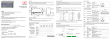
4.2.3 Electrical Connections, Pin Assignment
Source Cable/power supply Interface Terminal
PC2415-1/Y
RS422 / Encoder
PS 2020
Power supply
(optional)
PC2415-x
USB
12-pin male connector
17-pin male connector
Synchronization /
Ref. Encoder Switch / PC / Ethernet
PLC
PC
PC2415-x/OE
IF2001/USB
RS422/USB converter
(optional)
SC2415-x/OE
Analog output
Digital I/O
Encoder
A, B
Fig. 6 Connection examples for confocalDT IFD2411/2415
IFD2410/2415, 12-pin connector PC2415-x/OE PC2415-1/Y IF2001
Signal Pin Wire color Wire color RJ45, pin Signal
V+1 Red Red --- 24VDC
Supply GND 2 Blue Blue --- GND
Data Rx+ Encoder 2A+ 1 3 Brown Brown --- Tx+
Data Rx- Encoder 2A- 4 White White --- Tx-
Data Tx+ Encoder 2B+ 5 Green Green --- Rx+
Data Tx- Encoder 2B+ 6 Yellow Yellow --- Rx-
SYNC+ Encoder 2Ref+ 7 Gray Gray --- ---
SYNC- Encoder 2Ref- 8 Pink Pink --- ---
Shield Housing Black Black --- ---
Industrial Ethernet
9 White/green --- 3 ---
10 Green --- 6 ---
11 White/orange --- 1 ---
12 Orange --- 2 ---
Fig. 7 Pin assignment for 12-pin sensor connector
The PC2415-1/Y cable is included in the scope of delivery.
4
1
2
3
8
7
6
12
910
5
11
Fig. 8 12-pin sensor connector, pin side
1) The pins can be used for either:
- serial communication (TIA/EIA-422-B) and synchronization or
- encoder signals.

Page 19
Mounting | confocalDT IFD2410/2415
confocalDT 2410/2411/2415
IFD2410/2415, 17-pin connector SC2415-x/OE
The SC2415-x/OE cable is available as
an optional accessory.
7
9
15
16
6
5
8
12
1 11 10
13 4 14
2
3
17
Fig. 9 17-pin sensor connector, pin side
Signal Pin Wire color
Analog output 1 White, inside
Analog GND 2 Black
Switching output 2 GND 3 Black
Switching output 2 13 Purple
Multifunction input 1 5 Red
Multifunction input 2 14 Blue
Encoder 1B+ 8 Gray
Encoder 1B- 15 Pink
Encoder 1Ref+ 9 Green
Encoder 1Ref- 16 Yellow
Switching output 1 GND 10 Brown
Switching output 1 11 White
Encoder 1A- 12 Red/blue
Encoder 1A+ 17 Gray/pink
Shield Housing Black
Fig. 10 Pin assignment for 17-pin sensor connector
4.2.4 Grounding Concept, Shielding
All inputs and outputs are galvanically connected to the power supply ground (
supply
GND
); the Ethernet/EtherCAT connections are potential-free.
The ground connections (
supply GND
,
switching output GND
and
analog GND
)
of each connection group are galvanically connected to one another by filters.
The shield connections of each connection group are only connected to the controller
housing. They are used to connect the cable shieldings for individual connections (pow-
er, analog output, switching outputs, synchronization and trigger input).
i For reasons of interference resistance, use the corresponding GND connection for
the analog output and the two switching outputs.
Only use shielded cables shorter than 30 m and connect the cable shield to the
shield or the connector housings.
4.2.5 Supply Voltage (Power)
Nominal value: 24 V DC (20 ... 28 V, P < 7 W).
The sensor is supplied via cable PC2415-1/Y or PC2415-x/OE.
IFD2410
IFD2415
1
2
20 ...
28 VDC
IFD2410/2415
12-pin connector
Power supply PC2415-1/Y
PC2415-x/OE
1V+Red
2 GND Blue
Only turn on the power supply after wiring has been completed.
Connect the inputs for pin 1 and pin 2 on the sensor to a 24 V power supply.
i Power supply only for measuring devices, not to be used for drives or similar sources of impulse interference at the
same time. MICRO-EPSILON recommends using the optionally available PS2020 power supply, for the sensor.

Page 20
Mounting | confocalDT IFD2410/2415
confocalDT 2410/2411/2415
4.2.6 RS422
In addition to Industrial Ethernet, the IFD2410/2415 also supports serial communication via RS422. The PC2415-1/Y or
PC2415-x/OE cables enable serial communication. The IF2001/USB RS422-to-USB converter is available as an optional
accessory.
-Differential signals to EIA-422, galvanically connected to supply voltage.
-Receiver Rx with 120 Ohm internal terminating resistor.
Use a shielded cable with twisted wires.
Cable length less than 30 m.
Connect the ground connections.
IFD2410/2415
12-pin connec-
tor
Signal PC2415-1/Y
PC2415-x/OE
IF2001/USB
3 RX + Brown TX +
4 RX - White TX -
2 Supply GND (blue) GND
5 TX + Green RX +
6 TX - Yellow RX -
Housing Shield Cable shield ---
4.2.7 Ethernet, EtherCAT
Connection
-with an Ethernet network (PC) or
-with the EtherCAT bus system (IN port).
IFD2410/2415, 12-pin connector PC2415-x/OE PC2415-1/Y
PC2415-1/Y12-pin connector
Signal Pin Wire color RJ45, pin
Industrial Ethernet
9 White/green 3
10 Green 6
11 White/orange 1
12 Orange 2
Connect the IFD2410/2415 and network with a shielded Ethernet cable (Cat5E, 2 m patch cable from the scope of
delivery, total cable length shorter than 100 m).
The two LEDs
RUN
and
ERR
indicate that the connection was successful and is active.
The measuring device can be configured via SDOs (EtherCAT), the web interface or by ASCII commands at command
level (e.g. Telnet).
/