Page is loading ...

714-8/16 AND 715-8/16 ZONE
EXPANDERS
Installation Guide
DESCRIPTION
TXD
KYPD LX
Z13+
Z13-
Z14+
Z14-
Z15+
Z15-
Z16+
Z16-
Z9+
Z9-
Z10+
Z10-
Z11+
Z11-
Z12+
Z12-
Z5+
Z5-
Z6+
Z6-
Z7+
Z7-
Z8+
Z8-
Z1+
Z1-
Z2+
Z2-
Z3+
Z3-
Z4+
Z4-
BLK
GRN
YEL
RED
1k Ω EOL
TENS ONES
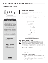
The 714-8 and 714-16 provide
an additional eight or sixteen
supervised zones for connecting
burglary and non-powered fire
alarm initiating devices to the panel.
The 715-8 and 715-16 provide an
additional eight or sixteen 12 VDC
ungrounded (Class B, Style A)
powered zones for connecting
two-wire smoke detectors.
The zone expanders provide
terminal strips, a jumper for LX-Bus
or Keypad Bus designation, and a
transmit data LED to indicate panel
communication.
All fire device installations
must be in accordance with the
manufacturer instructions, NFPA
standards, and Authority Having
Jurisdiction (AHJ) requirements.
Compatibility
• XT30/XT50 Panels and
XR150/XR550 Panels
• 714-8: 1k-4.7k Ohm EOL (LevE
and higher)
• 714-16: 1k Ohm EOL
• 715-8/715-16: 3.3k Ohm
What is Included?
• One 714-8, 714-16, 715-8, or 715-16
Zone Expander
• Eight or Sixteen 1K Ohm
Resistors (714-8/714-16) or 3.3K
Ohm Resistors (715-8/715-16)
• One Model 340 or 350 Enclosure
with Lock and Key
1
PROGRAM THE PANEL
After completing each of the following steps, press CMD to
advance to the next option. Refer to the panel programming guide
as needed.
1. Reset the panel and enter 6653 (PROG) at a keypad.
2. In ZONE INFORMATION, program the expansion zones as
any of the panel’s burglary or fire zone types. You can also
program zones as an Arming (AR) zone type when they are
being used with key switches.
3. Press CMD until STOP displays. Press a top row select key or
area to save programming.
MOUNT THE ENCLOSURE
2
Mount the enclosure in a secure, dry place. It is not necessary
to remove the zone expander circuit board when installing the
enclosure.
The enclosure can be surface or flush mounted using the holes
provided. Each of the four sides have dual 1/2” and 3/4” conduit
knockouts for running wires out of the enclosure. For more
information, refer to Figure 2.
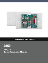
Figure 1: 714-16 Zone Expander
3
The zone expanders provide a 3-pin header with jumper used to
select the connection type.
To connect the expander to the Keypad Bus, place the jumper
across the two leftmost pins. To connect the expander to the LX-
Bus, place the jumper across the two rightmost pins. For more
information, refer to Figure 2.
Connect to the LX-Bus
To wire the 714-8/714-16, join the red, yellow, green, and black
wires to a 4-wire harness and connect it to the LX-Bus.
To wire the 715-8/715-16, connect the red wire to panel Terminal 11
(Smoke power terminal). This allows Sensor Reset to drop power
to the module and devices connected to its zones. Join the yellow,
green, and black wires to a 4-wire harness and connect it to the
LX-Bus.
WIRE THE ZONE EXPANDER

2 714-8/16 AND 715-8/16 INSTALLATION GUIDE | DIGITAL MONITORING PRODUCTS
SET THE ZONE EXPANDER ADDRESS
714-8/16 and 715-8/16 Point Zone Expanders use two rotary switches (TENS and ONES) to set the zone
expander address.
For keypad bus addresses, the ONES switch must be set to a starting address that communicates the status
of the first four zones (Z1 through Z4) on the expansion module. The next consecutive keypad address is
automatically used to communicate the status of the next four zones (Z5 through Z8), etc. For example, when
you set the TENS switch to 0 and the ONES switch to 2, the first four expander zones respond as zones 21
through 24. Expander zones 5 through 8 respond as panel zones 31 through 34, zones 9 through 12 respond as
panel zones 41 through 44, and zones 13 through 16 respond as panel zones 51 through 54. Refer to Table 1.
For LX-Bus addresses, set the switches to match the second two digits of the first panel zone being used. The
next 15 zone addresses communicate the status of the expander zones 2 through 16. For example, if you set
the TENS switch to 3 and the ONES switch to 2, the sixteen zones on the expander respond as panel zones
532 to 547 when connected to LX500. When connected to LX600, the zones respond as 632 to 647. Refer to
Table 2.
4
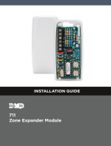
Figure 2: Zone Expander Wiring
From
Keypad Bus
or LX-Bus
TXD
KYPD LX
Z13+
Z13-
Z14+
Z14-
Z15+
Z15-
Z16+
Z16-
Z9+
Z9-
Z10+
Z10-
Z11+
Z11-
Z12+
Z12-
Z5+
Z5-
Z6+
Z6-
Z7+
Z7-
Z8+
Z8-
Z1+
Z1-
Z2+
Z2-
Z3+
Z3-
Z4+
Z4-
BLK
GRN
YEL
RED
714-16: 1k Ω EOL
714-8: 1k-4.7k Ω EOL
715-8/715-16: 3.3k Ω EOL
TENS ONES
Address Switches
0
1
2
3
4
5
6
7
8
9
S2
0
1
2
3
4
5
6
7
8
9
S1
TENS ONES
KYPD LX
KYPD LX
Keypad Bus/LX-Bus
Selection Jumper
Use LX-Bus
Use Keypad Bus
Mounting Holes
To panel
smoke detector
power circuit
To Zone Positive and Negative
Power
Supervision
Relay
3.3k EOL Model 309
2-Wire Smoke Detectors
To Zone Positive and Negative
3.3k Ω EOL Model 309
Smoke Wiring for
715-8/715-16
714-8/714-16:
Connect Red to LX-Bus Wire or Panel Terminal 7
715-8/715-16:
Connect Red to Panel Terminal 11
714-16 Module Specifications
Normal Operating Range 650-2100 Ohms
Zone Resistors 1k Ohm EOL
Max line impedance 100 Ohms
Zone Ground Fault 1500 Ohms or less
Zone Supervision All Zones
714-8 Module Specifications
Normal Operating Range 650-2100 Ohms
Zone Resistors 1k-4.7k Ohm EOL
Max line impedance 100 Ohms
Zone Ground Fault 1500 Ohms or less
Zone Supervision All Zones
715-8/715-16 Module Specifications
Normal Operating Range 1200-6000 Ohms
Zone Resistors 3.3k Ohm EOL
Max line impedance 100 Ohms
Zone Ground Fault 80 Ohms or less
Zone Supervision All Zones
Connect the 714-8/714-16 to the Keypad Bus
1. Connect the red, yellow, green, and black wires to panel Terminals 7, 8, 9, and 10 respectively.
2. Observe polarity and wire the zones.
3. For 714-8 expanders with hardware Level E or higher, install any resistor from 1k-4.7k Ohm. For 714-8 expanders
with hardware Level D or lower and 714-16 expanders, install the included 1KOhm EOL resistors.
Connect the 715-8/715-16 to the Keypad Bus
1. Connect the red wire to panel Terminal 11 (Smoke power terminal). This allows Sensor Reset to drop power to the
module and devices connected to its zones. Alternately, connect red to a regulated, power limited power supply
listed for Fire Protective Signaling through a Model 716 relay. Use the Sensor Reset Output programming to drop
power to the expander.
2. Connect the yellow, green, and black wires to panel Terminals 8, 9, and 10 respectively.
3. Observe polarity and wire the zones.
4. Install the included 3.3K Ohm EOL resistors.

714-8/16 AND 715-8/16 INSTALLATION GUIDE | DIGITAL MONITORING PRODUCTS 3
ADDITIONAL INFORMATION
Wiring Specifications
DMP recommends using 18 or 22 AWG for all LX-Bus and Keypad Bus connections. The maximum wire distance between
any module and the DMP Keypad Bus or LX-Bus circuit is 10 feet. To increase the wiring distance, install an auxiliary
power supply, such as a DMP Model 505-12. Maximum voltage drop between a panel or auxiliary power supply and any
device is 2.0 VDC. If the voltage at any device is less than the required level, add an auxiliary power supply at the end of
the circuit.
To maintain auxiliary power integrity when using 22-gauge wire on Keypad Bus circuits, do not exceed 500 feet. When
using 18-gauge wire, do not exceed 1,000 feet. Maximum distance for any bus circuit is 2,500 feet regardless of wire
gauge. Each 2,500 foot bus circuit supports a maximum of 40 LX-Bus devices.
For additional information refer to the LX-Bus/Keypad Bus Wiring Application Note (LT-2031) and the 710 Bus Splitter/
Repeater Module Installation Guide (LT-0310).
LED Operation
The LED on the zone expanders flashes each time the zone expander responds to a poll from the panel. If there is a
problem with the hardware, panel programming, or the green data wire between the panel and the zone expander zone
expander, the LED stops flashing and System Trouble appears in the keypad display.
KEYPAD
BUS
ADDRESS
SWITCHES ZONE NUMBERS
TENS ONES
XT30/XT50 AND
XR150 SERIES
XR550 SERIES
1 0 1 11 to 14 11 to 14
2 0 2 21 to 24 21 to 24
3 0 3 31 to 34 31 to 34
4 0 4 41 to 44 41 to 44
5 0 5 51 to 54 51 to 54
6 0 6 61 to 64 61 to 64
7 0 7 71 to 74 71 to 74
8 0 8 81 to 84 81 to 84
9 0 9 N/A 91 to 94
10 1 0 N/A 101 to 104
11 1 1 N /A 111 to 114
12 1 2 N /A 121 to 124
13 1 3 N/A 131 to 134
14 1 4 N/A 141 to 144
15 1 5 N/A 151 to 154
16 1 6 N /A 161 to 164
Table 1: Keypad Bus Addresses and Corresponding Zone Numbers
SWITCH XR150/XR550 SERIES XR550 SERIES
TENS ONES LX500 ZONES LX600 ZONES LX700 ZONES LX800 ZONES LX900 ZONES
0 0 500 500 - 515 600 600 - 615 700 700 - 715 800 800 - 815 900 900 - 915
0 1 501 501 - 516 601 601 - 616 701 701 - 716 801 801 - 816 901 901 - 916
0 2 502 502 - 517 602 602 - 617 702 702 - 717 802 802 - 817 902 902 - 917
0 3 503 503 - 518 603 603 - 618 703 703 - 718 803 803 - 818 903 903 - 918
0 4 504 504 - 519 604 604 - 619 704 704 - 719 804 804 - 819 904 904 - 919
... ... ... ... ... ... ... ... ... ... ... ...
8 0 580 580 - 595 680 680 - 695 780 780 - 795 880 880 - 895 980 980 - 995
8 1 581 581 - 596 681 681 - 596 781 781 - 796 881 881 - 896 981 981 - 996
8 2 582 582 - 597 682 682 - 697 782 782 - 797 882 882 - 897 982 982 - 997
8 3 583 583 - 598 683 683 - 698 783 783 - 798 883 883 - 898 983 983 - 998
8 4 584 584 - 599 684 684 - 699 784 784 - 799 884 884 - 899 984 984 - 999
Table 2: LX-Bus and Corresponding Zone Numbers

Designed, engineered, and
manufactured in Springfield, MO
using U.S. and global components.
LT-0401 1.06 20132
714-8/16 AND 715-8/16
ZONE EXPANDERS
Specifications
Operating Voltage 8.8 to 15.0 VDC
Operating Current
714-8/16
Average 20mA + 1.6mA per zone
Alarm 20mA + 2mA per zone
715-8/16
Average 20mA + 4mA per zone
+ 0.1 per 2-wire smoke
Alarm 20mA
+ 58mA per shorted zone
+ 0.1 per 2-wire smoke
+ 30mA per smoke in alarm
Dimensions
340 Enclosure 12.50” W x 9.50” H x 2.85” D
350 Enclosure 17.50” W x 13.50” H x 3.50” D
Ordering Information
714-8 714-8 in gray Model 340 enclosure
714-8-R 714-8 in red Model 340 enclosure
714-8L-G 714-8 in gray Model 350 enclosure
714-8L-R 714-8 in red Model 350 enclosure
714-8PCB 714-8 PCB only
714-16 714-16 in gray Model 340 enclosure
714-16-R 714-16 in red Model 340 enclosure
714-16L-G 714-16 in gray Model 350 enclosure
714-16L-R 714-16 in red Model 350 enclosure
714-16PCB 714-16 PCB only
715-8 715-8 in red Model 340 enclosure
715-8PCB 715-8 PCB only
715-16 715-8 in red Model 340 enclosure
715-16PCB 715-16 PCB only
Accessories
340-G Panel Enclosure, gray
340-R Panel Enclosure, red
350 -G Large Panel Enclosure, gray
350-R Panel Enclosure, red
350-GCAN Panel Enclosure, gray (Canada)
351ONQ ONQ wiring enclosure mounting plate
351PRI PRI wiring enclosure mounting plate
354 Retrofit Mounting Plate
354A Retrofit Mounting Plate
Certifications
California State Fire Marshal (CSFM)
New York City (FDNY COA #6167)
Underwriters Laboratory (UL) Listed
ANSI/UL 365 Police Station Connect Burglar
Alarm Systems
ANSI/UL 609 Local Burglar Alarm Units & Systems
ANSI/UL 864 Fire Protective Signaling Systems
ANSI/UL 985 Household Fire Warning System
Units
ANSI/UL 1023 Household Burglar Alarm System
Units
ANSI/UL 1076 Proprietary Burglar Alarm Units &
Systems
ANSI/UL 1610 Central Station Burglar Alarm Units
ANSI/UL 1635 Digital Alarm Communication
System Units
ULC Subject-C1023 Household Burglar
ULC/ORD-C1076 Proprietary Burglar
ULC S304 Central Station Burglar
ULC S545 Household Fire
TXD
KYPD LX
Z13+
Z13-
Z14+
Z14-
Z15+
Z15-
Z16+
Z16-
Z9+
Z9-
Z10+
Z10-
Z11+
Z11-
Z12+
Z12-
Z5+
Z5-
Z6+
Z6-
Z7+
Z7-
Z8+
Z8-
Z1+
Z1-
Z2+
Z2-
Z3+
Z3-
Z4+
Z4-
BLK
GRN
YEL
RED
1k Ω EOL
TENS ONES
INTRUSION • FIRE • ACCESS • NETWORKS
2500 North Partnership Boulevard
Springfield, Missouri 65803-8877
800.641.4282 | DMP.com
© 2020
COMPLIANCE LISTING SPECIFICATIONS
UL Commercial Burglary
To comply with ANSI/UL 365 Police-Connected Burglary System or ANSI/UL 609 Local Burglary Alarm Systems, the
zone expander must be mounted in the supplied, UL listed enclosure with a tamper.
UL Commercial Fire
See the panel installation guide for details for selecting compatible 2-wire smoke detectors. Any auxiliary power supply
used must be regulated, power limited and listed for Fire Protective Signaling.
ULC Commercial Burglary (XR150/XR550 Series Panels)
Place the zone expander zone expander in a listed enclosure and connect a DMP Model 307 Clip-on Tamper Switch to
the enclosure programmed as a 24-hour zone.
The 714/715 zones can be installed in medium or high risk applications when two zones are used as shown in the Dual
Zone Protection diagram in the XR150/XR550 Canadian Installation guide. Otherwise, 714/715 zones can only be used in
low risk applications.
ULC Residential Fire (XR150/XR550 Series Panels)
Refer to the appropriate panel compliance listing guide for the complete list of UL approved smoke detectors.
/