ADTRAN MX3 Job Aid

Type
Job Aid

ADTRAN MX3 is a versatile data backhaul platform that excels in diverse applications. With support for up to four DS3s, 28 DSX-1 drops, and optional modules for six additional DS1s, it seamlessly adapts to your evolving network needs.

ADTRAN MX3 is a versatile data backhaul platform that excels in diverse applications. With support for up to four DS3s, 28 DSX-1 drops, and optional modules for six additional DS1s, it seamlessly adapts to your evolving network needs.

MX3 Chassis
P/N: 1189001G3
CLEI: M3M2C00A_ _
MX3 CHASSIS
4. Connect the frame ground from the frame ground lug on the rear panel of the MX3 Chassis to the
equipment rack grounding screw using appropriately sized wire that is at least the same gauge as
the power wiring.
5. Test the frame ground connection to ensure proper ground. Using a multimeter set to its lowest
resistance range, place one lead on the rack’s ground strap and the other on the MX3 Chassis frame
ground terminal. The reading should be less than 0.1 ohm. Greater readings should be investigated.
6. Make power connections to the MX3 Chassis.
NOTE: A readily accessible disconnect device, such as a rackmount fuse and alarm panel that is
suitably approved and rated should be incorporated into the fixed wiring.
Connect to a reliably grounded –48 VDC or ±24 VDC source which is electrically isolated
from the AC source.
The branch circuit overcurrent protection should be a fuse or circuit breaker rated –48 VDC,
1.5 amp slow-blow or ±24 VDC, 3 amp slow-blow.
6a. Determine which fuse pairs are to supply power to the chassis.
6b. Remove the fuses from the A and B slots for the pair.
6c. Connect the ends of one wire between the “A” CO VDC supply and the
PWR A terminal on the
MX3 rear panel.
6d. Connect the three remaining wires in the same manner. Connect the “A” CO VDC return with
RET
A; “B” CO VDC supply with PWR B; and “B” CO VDC return with RET B.
7. Apply power and check voltages.
WARNING: Installing fuses in the fuse and alarm panel at this stage will provide power to the
chassis. There will be power to pins and connectors on the rear panel and inside the
chassis. Exercise caution to avoid electrical shock.
7a. Install appropriate fuses (1.5 amp slow-blow, –48 VDC or 3 amp slow-blow, ±24 VDC) in the
slots in the fuse and alarm panel that services the MX3 Chassis.
7b. Using a voltmeter, place the common (normally black) lead on the
RET A post of the DC power
terminal block and the DC volts (normally red) lead on the
PWR A post of the DC power
terminal block. For a –48 VDC supply the reading should be in the operating range of
–42 VDC to –60 VDC. For a ±24 VDC supply the reading should be in the range of ±22 VDC
to ±27 VDC.
7c. Repeat the above step for the RET/PWR B connections.
7d. Remove the fuses from the fuse and alarm panel servicing the MX3 Chassis.
7e. Install the protective cover over the power terminal block.
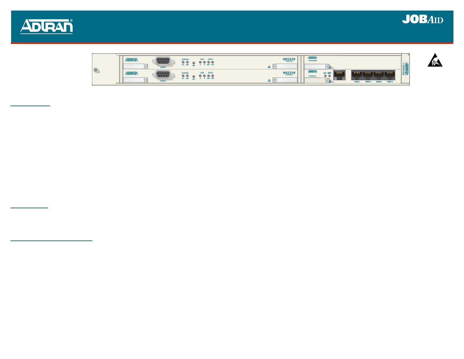
DESCRIPTION
The ADTRAN
®
MX3 Chassis is the foundation for a family of data backhaul products. Supporting up
to four DS3s, 28 DSX-1 drops, and two optional modules capable of processing up to six additional
DS1s, the MX3 platform is well suited to a variety of applications. The MX3 Chassis houses two hot-
swappable controller modules that provide 1:1 redundancy for the DS1 and DS3 interfaces. The
optional modules support a variety of non-redundant services.
WARNING: For configurations utilizing a single controller module, the empty controller module
slot must be occupied by a Controller Blank Plug (P/N 1189005G3). Likewise, empty
module slots must be occupied by a Module Blank Plug (P/N 1189006G3).
Features of the MX3 Chassis include the following:
1:1 Controller card redundancy
Hot-swappable controller and module cards
Optional fan module
NEBS Level 3 compliant
REAR PANEL
The MX3 Chassis rear panel (see illustration on reverse page) is equipped with an Ethernet port, an
alarm output terminal block, auxiliary input terminals, four sets of DS3 in/out jacks, two amphenol
connectors, and DC power connections.
INSTALLATION AND TURNUP
1. After unpacking the unit, inspect it for damage. If damage is found, file a claim with the carrier and
then contact ADTRAN Customer Service. Refer to the Warranty information at the bottom of the
reverse page.
2. Attach the mounting brackets to the MX3 Chassis using the two screws provided for each bracket.
For 19-inch rack applications, attach the brackets with the long flange to the side of the chassis. For
23-inch rack applications, attach the brackets with the short flange to the side of the chassis.
3. Use the appropriate rack type screws to mount the MX3 Chassis into the rack.
WARNING: Care should be taken to not upset the stability of the equipment rack after installation
is complete.
NOTE: The unit must be installed in accordance with the requirements of NEC NFPA 70.
When mounting the MX3 Chassis in a rack, multiple chassis can be mounted in adjacent rack
slots. To allow for proper heat dissipation, certain controller and module combinations may
require an optional Fan module (P/N 1189007G3) obtainable from ADTRAN. Refer to specific
controller card documentation for requirements.
61189001G3-22A
0711
B
A
ETHERNET
MX3RMM
*61189001G3-22A*
C A U T I O N !
SUBJECT TO ELECTROSTATIC DAMAGE
OR DECREASE IN RELIABILITY.
HANDLING PRECAUTIONS REQUIRED.
C A U T I O N !
SUBJECT TO ELECTROSTATIC DAMAGE
OR DECREASE IN RELIABILITY.
HANDLING PRECAUTIONS REQUIRED.
PRICING AND AVAILABILITY 800.827.0807
TECH SUPPORT 800.726.8663
RETURN FOR REPAIR 256.963.8722
www.adtran.com
61189001G3-22A
Warranty: ADTRAN will replace or repair this product within the warranty period if it does not meet its published specifications or fails while in service.
Warranty information can be found online at www.adtran.com/warranty
.
MX3 CHASSIS
WARNING: The DS3 (A-D), Alarm, and Ethernet interfaces MUST NOT be metallically connected
to interfaces which connect to the Outside Plant or its wiring. These interfaces are
designed for use as intra-building interfaces only. The addition of Primary Protectors
is not sufficient protection in order to connect these interfaces metallically to OSP
wiring. This also applies to T/R (DSX-1) interfaces unless otherwise specified by the
controller card documentation.
8. For system management, use CAT 5 cable to connect from the Ethernet network into the female
RJ-45 port labeled
ETHERNET on the MX3 Chassis rear panel.
9. Connect the DS3 interfaces to the BNC connectors, labeled A - D, as needed for the controller. The
receive data from the network is connected to the
IN connectors. The transmit data from the MX3
Chassis is connected to the
OUT connectors.
NOTE: DS3 interfaces must be connected using coaxial cables that have the shields grounded at both
ends.
10. Connect the DSX-1 interfaces to the 64-pin
T/R (IN) and T/R (OUT) amphenol receptacles (female).
NOTE: When looking at the back of the chassis, right exit cables should be used to avoid conflict with
alarm/aux connections, the network management port connection, and DS3 connections.
11. Connect the
CRIT (critical), MAJOR, and MINOR alarm leads from the fuse and alarm panel to the
Common (
C), Normally Open (NO), and Normally Closed (NC) wire-wrap terminals on the MX3
Chassis rear panel as required.
12. Connect the AUX INPUTS (1–15) as specified in the controller card documentation.
13. After steps 11 and 12 have been completed, install the protective cover over the wire-wrap headers.
14. Power may now be applied to the chassis by installing appropriate fuses (1.5 amp slow-blow, –48
VDC or 3 amp slow-blow, ±24 VDC) in the fuse and alarm panel that services the MX3 Chassis.
COMPLIANCE
The MX3 Chassis complies with the requirements covered under UL 60950, NEBS Level 3, and RoHS
Directive 2002/95/EC. It is intended to be installed in restricted access areas only.
This device complies with Part 15 of the FCC rules. Operation is subject to the following two
conditions: (1) This device may not cause harmful interference, and (2) this device must accept any
interference received, including interference that may cause undesired operation.
Code Input Output
Power Code (PC) F C
Telecommunication Code (TC) X
Installation Code (IC) A
Changes or modifications not expressly approved by ADTRAN could void the users authority to
operate this equipment.
CAUTION: Per GR-1089-CORE October 2002, Section 9, this system is designed and intended only
for installation in a DC-C (common) Bonding and Grounding system. It is not intended or
designed for installation in a DC-I (isolated) Bonding and Grounding system.
FUSE REQUIREMENTS
The following table provides the fuse requirements for all MX3 Chassis installations.
MX3 AMPHENOL CONNECTOR PIN ASSIGNMENTS
System Voltage Required Fuse
–48 VDC 1.5 amp, slow-blow
±24 VDC 3 amp, slow-blow
Pin Function Pin Pin Function Pin
1 Ring 1 Tip 1 33 17 Ring 17 Tip 17 49
2 Ring 2 Tip 2 34 18 Ring 18 Tip 18 50
3 Ring 3 Tip 3 35 19 Ring 19 Tip 19 51
4 Ring 4 Tip 4 36 20 Ring 20 Tip 20 52
5 Ring 5 Tip 5 37 21 Ring 21 Tip 21 53
6 Ring 6 Tip 6 38 22 Ring 22 Tip 22 54
7 Ring 7 Tip 7 39 23 Ring 23 Tip 23 55
8 Ring 8 Tip 8 40 24 Ring 24 Tip 24 56
9 Ring 9 Tip 9 41 25 Ring 25 Tip 25 57
10 Ring 10 Tip 10 42 26 Ring 26 Tip 26 58
11 Ring 11 Tip 11 43 27 Ring 27 Tip 27 59
12 Ring 12 Tip 12 44 28 Ring 28 Tip 28 60
13 Ring 13 Tip 13 45 29 N/A N/A 61
14 Ring 14 Tip 14 46 30 N/A N/A 62
15 Ring 15 Tip 15 47 31 N/A N/A 63
16 Ring 16 Tip 16 48 32 FGND FGND 64
  • Page 1 1
  • Page 2 2

ADTRAN MX3 Job Aid

Type
Job Aid

ADTRAN MX3 is a versatile data backhaul platform that excels in diverse applications. With support for up to four DS3s, 28 DSX-1 drops, and optional modules for six additional DS1s, it seamlessly adapts to your evolving network needs.

Ask a question and I''ll find the answer in the document

Finding information in a document is now easier with AI