C A U T I O N !
SUBJECT TO ELECTROSTATIC DAMAGE
OR DECREASE IN RELIABILITY.
HANDLING PRECAUTIONS REQUIRED.
MX3 Remote
Management Module
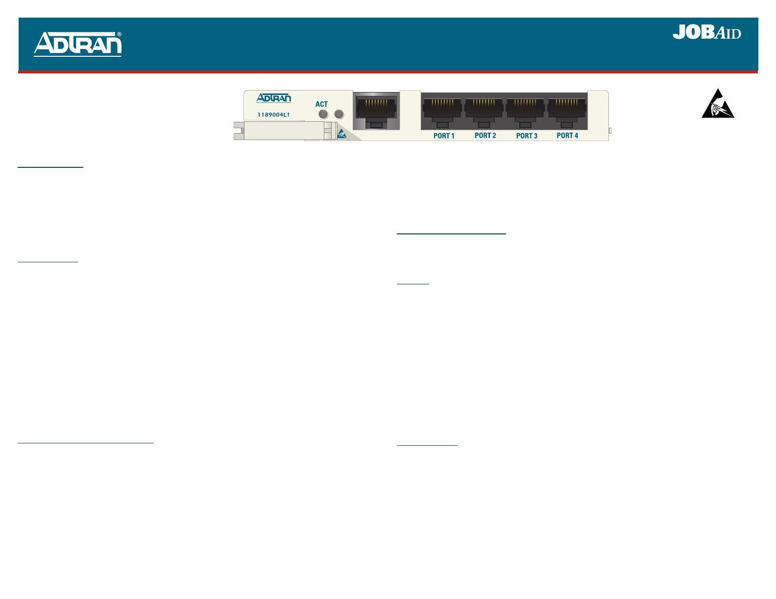
P/N: 1189004L1
CLEI: M3LINT0A_ _
MX3 REMOTE MANAGEMENT MODULE
ADTRAN logo) and right (to the right of Port 4) of the MX3RMM to ensure a good seat of the
MX3RMM pins into the backplane connector.
3. Push the ejector latch against the front panel until it latches.
The MX3RMM initializes and begins a self-test upon insertion into a powered MX3 Chassis. When the
self-test completes the LEDs will reflect the true state of the card.
CONNECT AND LOGON
The MX3 Controller provides the management interface for the MX3RMM. The MX3RMM is
accessed by selecting
MX3RMM from the controller main menu. Refer to specific controller card
documentation for information about connecting and logging in to the system.
Ethernet
The Ethernet jack (ETHERNET) located on the MX3RMM front panel provides LAN access to the
Network. From this port, devices located on the local area network can be remotely managed. This port
has automatic rate detection and performs MDI/MDI-X crossover detection eliminating the need for a
crossover cable. The port can be accessed using standard CAT 5 cable with an RJ-45 connector. The
pin assignments for the RJ-45 connector are listed in the Ethernet Pin List on the reverse page.
WARNING: The Ethernet and Terminal Server Port 1-4 interfaces MUST NOT be metallically
connected to interfaces which connect to the Outside Plant or its wiring. These
interfaces are designed for use as intra-building interfaces only. The addition of
Primary Protectors is not sufficient protection in order to connect these interfaces
metallically to OSP wiring.
When the MX3RMM is installed, the MX3 Chassis rear panel Ethernet interface is redirected to the
MX3RMM and is bridged onto the local area network. Thus, the rear panel Ethernet jack can also be
used for network access.
Terminal Server
The MX3RMM contains four RS-232 interfaces (PORT1, PORT 2, PORT 3, and PORT 4) that provide
the ability to remotely connect to RS-232 managed devices.
WARNING: The 8 pin modular jacks used for the Terminal Server Port 1- 4 interfaces should never
be connected to a telecommunications network and are intended for connection to
RS-232 data interfaces only.
These ports are accessed by establishing a Telnet session to the MX3 system with the port number of
the particular port. The pin assignments for each of the RS-232 interfaces are listed in the PORT 1-4
Terminal Connector Pin List (below).
DESCRIPTION
The ADTRAN
®
MX3 Remote Management Module (MX3RMM) is a plug-in module for the MX3
Chassis (P/N 1189001L1) that provides the capability to remotely manage the MX3 system. The
MX3RMM bridges Ethernet traffic between two Point-to-Point Protocol (PPP) over T1/FT1 interfaces,
a front panel Ethernet jack and the rear chassis Ethernet jack. Both Ethernet jacks provide LAN access
giving a user the ability to remotely manage other systems located on the same network. Additionally,
four terminal server ports located on the front panel provide the capability to remotely manage external
RS232 devices.
LED STATUS
The MX3RMM front panel provides two LEDs for displaying activity and network information. The
NET LED displays status information about both network interfaces. If one of the network interfaces is
disabled, the
NET LED will only show information concerning the enabled network interface. Front
panel LED states are defined as follows:
ACT ! Green..........................Operation is normal
! Red.............................Card failure
! Amber ........................Link present on front panel Ethernet jack
4 Amber (Flashing).......Console open
NET ! Green..........................Network interface is operating and normal
4 Amber (Flashing
once per event)...........Network traffic present on active network interface
! Red.............................LOS on active network interface
! Amber ........................Network interface in test
" Off..............................Network interface not enabled
INSTALLATION AND TURNUP
After unpacking the unit, inspect it for damage. If damage has occurred, file a claim with the carrier,
then contact ADTRAN Customer Service. Refer to the Warranty information at the bottom of the
reverse page.
This module occupies an expansion slot in the MX3 Chassis. Follow the steps listed below to install
the MX3RMM.
1. Pull the ejector latch at the left side of the MX3RMM front panel from the latched or closed
position.
2. Gently, but firmly, slide the MX3RMM into the upper or lower expansion slot taking note of the
left and right guide grooves in the chassis. Simultaneously, apply thumb pressure at the left (on the
61189004L1-22B
0502
NETNET
ETHERNET
MX3RMM
*61189004L1-22B*


