Page is loading ...

Crestron Electronics, Inc. Installation Guide - DOC. 7529A
15 Volvo Drive Rockleigh, NJ 07647 (2036482)
Tel: 888.CRESTRON 09.13
Fax: 201.767.7576 Specifications subject to
www.crestron.com change without notice.
This product is Listed to applicable
UL Standards and requirements by
Underwriters Laboratories Inc.
Further Inquiries
To locate specific information or resolve questions after reviewing this guide, contact Crestron's True Blue Support at
1-888-CRESTRON [1-888-273-7876] or, for assistance within a particular geographic region, refer to the listing of
Crestron worldwide offices at www.crestron.com/offices.
To post a question about Crestron products, log onto Crestron’s Online Help at www.crestron.com/onlinehelp.
First-time users must establish a user account to fully benefit from all available features.
Future Updates
As Crestron improves functions, adds new features and extends the capabilities of the GLS-OIR-C-CN, additional
information may be made available as manual updates. These updates are solely electronic and serve as
intermediary supplements prior to the release of a complete technical documentation revision.
Check the Crestron Web site periodically for manual update availability and its relevance. Updates are identified as
an “Addendum” in the Download column.
WARNING: To avoid fire, shock, or death; turn off power at circuit breaker or fuse and test that power is off before
wiring!
NOTES: Observe the following points.
• To be installed and/or used in accordance with appropriate electrical codes and regulations.
• This product should be installed by a qualified electrician.
• Sensors must be mounted on a vibration free surface.
PREPARING AND CONNECTING WIRES
Strip the ends of the wires approximately 1/4 in (6 mm). Use care to avoid nicking the conductors. Twist together
the ends of the wires that share a connection. Apply solder only to the ends of the twisted wires. Avoid tinning too
far up the wires or the ends become brittle.
Crestron GLS-OIR-C-CN
Passive Infrared Occupancy Sensor with Cresnet
®
Installation Guide
DESCRIPTION
The Crestron
®
Passive Infrared Occupancy Sensor with Cresnet
®
is a low-voltage passive
infrared (PIR) sensor that is directly wired through Cresnet to automatically control lighting or
any other system wide device. The sensor is typically used to turn lights on when a room or
area is occupied and to shut them off when the room or area is vacated. The exact behavior
of the sensor can be configured via software or the IR remote (GLS-REMOTE-ODT/OIR,
sold separately). The passive infrared motion detection provides high immunity to false
triggering and yields a sensor with a 360 degree 2000 square feet coverage area with
excellent performance. Additionally, an integrated photocell allows for easy and custom
adjustments for even the most robust of daylight harvesting applications.
MOUNTING/MASKING LOCATION DIAGRAM
The supplied masks mount in the sensor cover to block the PIR sensor. The half mask is
supplied to allow half of the sensor to be masked. The perforated mask has twelve 30º
removable segments that allow masking particular areas to prevent undesireable triggers
from affecteng the sensor operation.
Masking is not required in the corner mounting application shown below because it cannot
see through a door. By masking a portion of the sensor, traffic through a hallway can be
ignored as in the second example. The following illustrations provide typical application
examples.
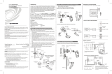
TYPICAL APPLICATION DIAGRAMS
The following diagrams illustrate the typical wiring of a GLS-OIR-C-CN.
Wire GLS-OIR-C-CN
INSTALLATION
The GLS-OIR-C-CN can be installed into a drop ceiling, drywall, or an octagon electrical box.
Refer to the instructions that follow to install the sensor.
The following items are included with the GLS-OIR-C-CN for installation:
• 1/2 Solid PIR mask (1)
• 1/12 Perforated PIR mask (1)
• Hole cutout template (1)
The following items are required for installation:
• Slotted/Phillips screwdriver
• Pencil
• Cutting tools
NOTE: Before securing the sensor to the ceiling, refer to the “Mounting/Masking Location”
and “Detection Range” sections to choose the best orientation. Avoid areas where false
tripping may occur due to outside motion such as an open door. Identify and avoid areas of
possible vibrations and air currents (e.g., projectors, fans, vents) and mount the sensor at
least 5 feet (2 meters) away from these items.
Install Into Drop Ceiling or Drywall
1. Select the location for mounting the sensor and proper masking for the application.
2. Use the supplied hole cutout template to mark the ceiling where the sensor is to be
mounted.
3. Use cutting tools appropriate for the surface to create a hole in the ceiling.
4. Turn the sensor cover counterclockwise to separate it from the GLS-OIR-C-CN.
Install Into Octagon Electrical Box
1. Select the location for mounting the sensor and proper masking for the application.
2. Turn the sensor cover counterclockwise to separate it from the device.
3. Using a Phillips screwdriver, unscrew the the preinstalled screws from the plastic wings
and remove them from the sensor.
4. Mount the GLS-OIR-C-CN to the octagon electrical box using two screws (not
supplied).
Mounting to Octagon Electrical Box
Cresnet
Crestron
Control System
or CLS-C6
External
Photocell
Cresnet
Crestron
Control System
or CLS-C6
Octagon
Electrical
Box
GLS-OIR-C-CN
(Cover Removed)
Mounting Screws
(Not Supplied)
Cover
5. Place the GLS-OIR-C-CN into the hole and secure the sensor to the drywall or ceiling
tile using the preinstalled screws. The preinstalled screws have plastic “wings” that
secure the occupancy sensor to the ceiling. When the screws are tightened the wings
open and clamp against the surface of the ceiling. The screws should be secured
tightly enough so that the device cannot spin in the ceiling opening. Refer to the
illustration below for a typical mounting scenario.
Mount GLS-OIR-C-CN to Drywall or Drop Ceiling
6. Place the cover on the device and twist to secure. Align the arrows on the device with
the arrows under the cover. Twist the cover clockwise. The cover snaps into place.
Wire GLS-OIR-C-CN with Photocell
5. Place the cover on the device and twist to secure. Align the arrows on the device with
the arrows under the cover. Twist the cover clockwise. The cover snaps into place.
GLS-OIR-C-CN
(Cover Removed)
Cover
Ceiling
0
(0)
5
(2)
10
(3)
15
(5)
20
(6)
25
(8)
5
(2)
10
(3)
15
(5)
20
(6)
25
(8)
30
(10)
(m)
0 (0)
5 (2)
10 (3)
15 (5)
5 (2)
10 (3)
15 (5)
(m)
20 (6)
25 (8)
20 (6)
25 (8)
30
(10)
30 (10)
Top View
8 1/2 ft (2.6 m)
Ceiling Height
DETECTION RANGE
High PIR Sensitivity Setting
The detection pattern for the high PIR sensitivity setting is shown in the illustrations below.
The first illustration shows the side view of the detection range and the second illustration
shows the detection range based on the top view of the sensor.
0 ft (0 m)
8 ft (2.4 m)
8.5 ft (2.6 m)
10 ft (3 m)
12 ft (4 m)
0
(0)
5
(2)
10
(3)
15
(5)
20
(6)
25
(8)
5
(2)
10
(3)
15
(5)
20
(6)
25
(8)
30
(10)
30
(10)
ft
(m)
SIDE VIEW

VERIFY OPERATION
After the GLS-OIR-C-CN is installed its installation location and operation should be verified.
Confirm Installation Location
Verify the installation location by entering the room, closing any doors and sitting in the room
while observing the device’s LED. While sitting still, verify that the sensor only detects actual
motion and is not affected by any projectors, fans, vents, etc. Monitor the LED activity on the
device. A properly installed occupancy sensor should have no LED activity when there is no
motion in the room.
Adjust Occupancy Sensitivity
NOTE: If multiple occupancy sensors are located in the same room, adjust one at a time.
1. Press and hold OCC SETUP for 3 seconds on the IR remote to enter Occupancy
Setup mode.
2. Set the room sensitivity based on the illustrations in the “Detection Range” section on
the previous page.
3. Walk around the room to simulate typical room motion (e.g., sit at various places
around a conference table and simulate typical motion for a conference room).
4. Verify LED indication of motion (red for PIR).
5. Adjust sensitivity levels, if necessary, to maintain occupancy of the room. If no motion
is detected in main areas of the room, increase the sensitivity. If no motion is detected
in the corners of the room, increase the timeout to allow greater chance of detecting
motion.
6. Repeat these steps until all expected motion is detected.
Adjust Vacancy Sensitivity
1. In Vacancy Setup mode, verify that nothing triggers occupancy when the room is
vacant. When in Vacancy Setup mode the occupancy sensor beeps to indicate motion.
The occupancy sensor should beep when re-entering the room.
2. Using the IR remote, place the sensor into vaccancy setup mode by pressing the VAC
SETUP button. Exit the room and close the door.
3. Listen for beeps that indicate there is motion detected in the room.
4. Walk by open door ways or entrances/exits to ensure that no false occupancies are
being detected.
5. If unwanted motion is detected, lower the PIR setting and retest.
TROUBLE POSSIBLE CAUSE CORRECTIVE ACTION
Lights do not
turn on.
Circuit breaker or fuse
has tripped.
Reset circuit breaker or replace fuse.
Incorrect programming
in control system.
Check control system logic or contact
Crestron for assistance
Connection on back of
sensor is miswired.
Check that all Cresnet wires are wired to
their respective terminals.
Incorrect settings on
device.
Increase the sensitivity to the next highest
setting on the PIR sensor.
Incorrect mounting
location.
Move the sensor into an area that can
"see" the occupant or point of motion.
Lights do not
turn off.
Constant motion. To test, reduce sensitivity level and
remove motion source. If there is no
change, then the mounting location must
move.
Sensor can "see" too
far into hallway or other
room.
To test, put the sensor into the Setup
mode and walk by the area. If the red LED
continues to blink, move the sensor or use
masks on the PIR.
Incorrect settings on
device.
Reduce the sensitivity and timeout levels
one step at a time.
Incorrect programming
in control system.
Check control system logic or contact
Crestron for assistance.
Lights remain
on too long.
Timeout setting is too
high.
Reduce the timeout one step at a time.
OPERATION
The descriptions below refer to a system which has been configured to turn the lights on
when a room or area is occupied and turn them off when the room or area is vacated.
• Timeout - The sensor is designed to turn the lights off if no motion is detected after a
specified time. This length of time is called the delayed-off time and is set using the
IR remote. The duration is the amount of time after the last instance of motion until
the lights turn off.
• Short Timeout - This walk-through feature is useful when a room is momentarily
occupied. With this feature, the sensor turns the lights off shortly after the person
leaves the room.
The short-timeout feature works as follows: When a person enters the room, the
lights turn on. If the person leaves the room before the short-timeout threshold of 90
seconds has elapsed, the timeout reverts to 60 seconds in order to turn the lights off
sooner. If the programmed timeout happens to be less than 60 seconds during
normal operation, that timeout value takes precedence.
• LED Operation - The LED flashes when motion is detected. The LED flash can be
disabled using the LED disable switch setting. Red flash indicates motion detection
by passive infrared technology.
PHOTOCELL ADJUSTMENT
The GLS-OIR-C-CN has a built in photocell that allows for complete daylight harvesting
using the Crestron lighting system. Through programming, the photocell can dim lights or
choose to not turn lights on at all if sufficient natural daylight is present. An external photo
sensor can be connected directly to the occupancy sensor through the EXT port on the rear
of the device to provide additional daylight harvesting capabilities.
SETUP AND CONFIGURATION
• Short Timeout - Press SHORT TIMEOUT - ENABLE or SHORT TIMEOUT -
DISABLE to enable or disable Short Timeout mode. Short timeout allows the timout to
be set to 60 seconds when occupied for less than 90 seconds.
• LED - Press LED - ENABLE or LED - DISABLE to enable or disable the LED of the
device during normal operation.
• Timeout - Press the desired TIMEOUT - 30s/2m/5m/10m/15m/30m button to set the
timout.
Setup and configuration of the GLS-OIR-C-CN is performed using the
GLS-REMOTE-ODT/OIR remote. Refer to the GLS-REMOTE-ODT/OIR Operations Guide
(Doc. 7541) at www.crestron.com/manuals.
NOTE: Press the setup button on the sensor to acknowledge Cresnet identification.
The specific patents that cover Crestron products are listed at patents.crestron.com.
Crestron, the Crestron logo, and Cresnet are either trademarks or registered trademarks of Crestron
Electronics, Inc. in the United States and/or other countries. UL and the UL logo are either trademarks
or registered trademarks of Underwriters Laboratories, Inc. in the United States and/or other countries.
Other trademarks, registered trademarks, and trade names may be used in this document to refer to
either the entities claiming the marks and names or their products. Crestron disclaims any proprietary
interest in the marks and names of others. Crestron is not responsible for errors in typography or
photography.
This document was written by the Technical Publications department at Crestron.
©2013 Crestron Electronics, Inc.
Return and Warranty Policies
Merchandise Returns / Repair Service
1. No merchandise may be returned for credit, exchange or service without prior authorization
from Crestron. To obtain warranty service for Crestron products, contact an authorized
Crestron dealer. Only authorized Crestron dealers may contact the factory and request an
RMA (Return Merchandise Authorization) number. Enclose a note specifying the nature of
the problem, name and phone number of contact person, RMA number and return address.
2. Products may be returned for credit, exchange or service with a Crestron Return
Merchandise Authorization (RMA) number. Authorized returns must be shipped freight
prepaid to Crestron, 6 Volvo Drive, Rockleigh, N.J. or its authorized subsidiaries, with RMA
number clearly marked on the outside of all cartons. Shipments arriving freight collect or
without an RMA number shall be subject to refusal. Crestron reserves the right in its sole
and absolute discretion to charge a 15% restocking fee plus shipping costs on any products
returned with an RMA.
3. Return freight charges following repair of items under warranty shall be paid by Crestron,
shipping by standard ground carrier. In the event repairs are found to be non-warranty,
return freight costs shall be paid by the purchaser.
Crestron Limited Warranty
Crestron Electronics, Inc. warrants its products to be free from manufacturing defects in materials
and workmanship under normal use for a period of three (3) years from the date of purchase from
Crestron, with the following exceptions: disk drives and any other moving or rotating mechanical
parts, pan/tilt heads and power supplies are covered for a period of one (1) year; touch screen
display and overlay components are covered for 90 days; batteries and incandescent lamps are not
covered.
This warranty extends to products purchased directly from Crestron or an authorized Crestron
dealer. Purchasers should inquire of the dealer regarding the nature and extent of the dealer's
warranty, if any.
Crestron shall not be liable to honor the terms of this warranty if the product has been used in any
application other than that for which it was intended or if it has been subjected to misuse, accidental
damage, modification or improper installation procedures. Furthermore, this warranty does not cover
any product that has had the serial number altered, defaced or removed.
This warranty shall be the sole and exclusive remedy to the original purchaser. In no event shall
Crestron be liable for incidental or consequential damages of any kind (property or economic
damages inclusive) arising from the sale or use of this equipment. Crestron is not liable for any
claim made by a third party or made by the purchaser for a third party.
Crestron shall, at its option, repair or replace any product found defective, without charge for parts
or labor. Repaired or replaced equipment and parts supplied under this warranty shall be covered
only by the unexpired portion of the warranty.
Except as expressly set forth in this warranty, Crestron makes no other warranties, expressed or
implied, nor authorizes any other party to offer any warranty, including any implied warranties of
merchantability or fitness for a particular purpose. Any implied warranties that may be imposed by
law are limited to the terms of this limited warranty. This warranty statement supersedes all previous
warranties.
TROUBLESHOOTING
The following table provides corrective action for possible trouble situations. If further
assistance is required, please contact a Crestron customer service representative.
GLS-OIR-C-CN Troubleshooting
Medium PIR Sensitivity Setting
The detection pattern for the medium PIR sensitivity setting is shown in the illustrations
below. The first illustration shows the side view of the detection range and the second
illustration shows the detection range based on the top view of the sensor.
Low PIR Sensitivity Setting
The detection pattern for the low PIR sensitivity setting is shown in the illustrations below.
The first illustration shows the side view of the detection range and the second illustration
shows the detection range based on the top view of the sensor.
Top View
8 1/2 ft (2.6 m)
Ceiling Height
0
(0)
5
(2)
10
(3)
15
(5)
20
(6)
25
(8)
5
(2)
10
(3)
15
(5)
20
(6)
25
(8)
30
(10)
(m)
0 (0)
5 (2)
10 (3)
15 (5)
5 (2)
10 (3)
15 (5)
(m)
20 (6)
25 (8)
20 (6)
25 (8)
30
(10)
30 (10)
Top View
8 1/2 ft (2.6 m)
Ceiling Height
0
(0)
5
(2)
10
(3)
15
(5)
20
(6)
25
(8)
5
(2)
10
(3)
15
(5)
20
(6)
25
(8)
30
(10)
(m)
0 (0)
5 (2)
10 (3)
15 (5)
5 (2)
10 (3)
15 (5)
(m)
20 (6)
25 (8)
20 (6)
25 (8)
30
(10)
30 (10)
0 ft (0 m)
8 ft (2.4 m)
8.5 ft (2.6 m)
10 ft (3 m)
12 ft (4 m)
0
(0)
5
(2)
10
(3)
15
(5)
20
(6)
25
(8)
5
(2)
10
(3)
15
(5)
20
(6)
25
(8)
30
(10)
30
(10)
ft
(m)
SIDE VIEW
0 ft (0 m)
8 ft (2.4 m)
8.5 ft (2.6 m)
10 ft (3 m)
12 ft (4 m)
0
(0)
5
(2)
10
(3)
15
(5)
20
(6)
25
(8)
5
(2)
10
(3)
15
(5)
20
(6)
25
(8)
30
(10)
30
(10)
ft
(m)
SIDE VIEW
/