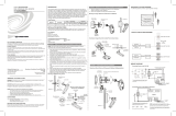
Mounting and Masking Locations
Two masks (a half mask and perforated mask) are included with the sensor and are used
to prevent unwanted motion detection. The half mask blocks motion from being detected
from half of the motion detector. The perforated mask has twelve 30-degree removable
segments to allow custom masking. The selected mask is installed under the cover of the
sensor to conceal the lens.
NOTE: The half mask comes pre-installed. If a different mask is to be used, it should
be installed in the same manner as the half mask.
Refer to the following illustrations for typical mounting applications.
Typical Mounting and Masking Locations
Test Mode
Test mode allows the GLS-OIR-CSM-EX-BATT to be tested to ensure that the sensor is
triggered by the proper amount of motion. It also allows for the RF ID and rmware to be
updated more efciently.
To enter Test mode, hold the TEST button for 4 seconds. The green LED ashes to
indicate the device is powered and has entered Test mode.
When the device is in Test mode, the green LED ashes once to indicate that initial motion
has been detected. The red LED lights when motion is detected and stays lit if continuous
motion is sensed. Timeout settings do not take effect and no information is sent to the
control system during Test mode. After nal vacancy is detected, the green LED ashes
once.
The sensor exits Test mode once the TEST button is pressed or after 5 minutes. When
exiting Test mode, the sensor’s green LED ashes. When the sensor exits Test mode, it
enters Light Sleep mode. When in Light Sleep mode, the sensor checks for updates from
the control system (such as new rmware or RF ID changes) every 30 seconds.
NOTE: When the GLS-OIR-CSM-EX-BATT is in Test mode all the functionality of Light
Sleep mode is available.
Set the RF ID
It is recommended to have direct access to the GLS-OIR-CSM-EX-BATT and
to use Crestron Toolbox™ to set the RF ID of the device. Set the RF ID for the
GLS-OIR-CSM-EX-BATT by doing the following.
1. Wake the device by pressing the TEST button on the GLS-OIR-CSM-EX-BATT.
2. Set the RF ID of the device using Crestron Toolbox. The RF ID must match the RF ID
specied in the Crestron Studio™ or SIMPL Windows program.
3. Press the TEST button on the GLS-OIR-CSM-EX-BATT to ensure that the device is
still awake and the RF ID is transferred to the device.
The RF ID can also be set by placing the device into Setup mode.
1. Press the TEST button for more than 4 seconds. The LED ashes.
2. Set the RF ID using Crestron Toolbox. Setup mode is exited after 5 minutes.
Firmware Upgrade
NOTE: Before using the GLS-OIR-CSM-EX-BATT, ensure the device is using the
latest rmware. Check for the latest rmware for the GLS-OIR-CSM-EX-BATT at
www.crestron.com/rmware. Load the rmware onto the device using Crestron
Toolbox™ software.
To upgrade the rmware on the GLS-OIR-CSM-EX-BATT, follow the procedure below using
Crestron Toolbox (v. 2.36.216 or later):
1. Select Tools > Network Device Tree View.
2. Right-click the gateway in the Network Device Tree View window.
3. Select Functions > Firmware Upload (Deep Sleep).
4. Click the Load Firmware File button in the Firmware Upload (Deep Sleep) window
and browse for the rmware in the Open window.
5. Once the rmware is selected, click Open to add the rmware to Firmware Images.
6. In the Assignments section, click the device (CTRL + click or SHIFT + click for multiple
devices) that the rmware should be assigned to. The row turns light gray.
NOTE: If a device is not located in the Assignments section, click Show all
Available IDs.
NOTE: If a deep sleep device has not been acquired by the gateway, assign the
rmware to an ID if the future ID number of the device is known.
7. In the Firmware Images section, click the rmware that should be assigned to the
device(s). The row turns light gray.
8. Once the device(s) and rmware are selected, click Assign Selected Image to
Selected Target(s) to assign the rmware to the device(s). The rmware is stored on
the gateway and assigned to the device(s).
9. Select a method to initiate the rmware upgrade on the GLS-OIR-CSM-EX-BATT:
• Allow the GLS-OIR-CSM-EX-BATT to automatically initiate the rmware upgrade,
which occurs every 24 hours.
• To manually initiate the rmware upgrade, enter or exit the room—the occupancy
sensor initiates the rmware upgrade once it detects occupancy or vacancy.
Replace the Battery
Use the following procedure to replace the battery in the GLS-OIR-CSM-EX-BATT:
CAUTION: The battery used in this device may present a risk of re or chemical burn
if mistreated. Do not recharge, disassemble, heat above 212 °F (100 °C), or incinerate.
Replace the battery with an Ultralife 9 volt lithium battery only. Use of another battery
may present a risk of re or explosion.
1. Rotate the cover of the sensor counterclockwise to remove the cover.
2. Remove the battery from the sensor.
3. Disconnect the battery from the two terminals in the sensor.
4. Connect the new battery to the two terminals in the sensor and secure the battery into
the housing.
5. Rotate the cover of the sensor clockwise onto the installed base until it is secured in
place. The assembly clicks when secured.
NOTE: Dispose of a used battery promptly. Keep away from children. Do not
disassemble and do not dispose of in re.
Wireless Communications
The device connects to the Crestron network via the inNET EX communications protocol.
Use the procedures outlined below to join or leave an inNET EX network and to verify
communications between the device and the control system.
Joining an inNET EX Network
Before a device can be used in a lighting system, it must rst join an inNET EX network by
being acquired by an inNET EX gateway:
NOTE: A device can be acquired by only one gateway.
1. Put the inNET EX gateway into Acquire mode from the unit itself or from Crestron
Toolbox, as described in the gateway’s manual at www.crestron.com/manuals.
NOTE: In an environment where multiple gateways are installed, only one gateway
should be in Acquire mode at any time.
2. Place the device into Acquire mode by doing the following:
a. Tap the TEST button three times then press and hold it down (tap-tap-tap-
press+hold) until the green LED on the device ashes once (this can take up to 10
seconds).
b. Release the button to start the acquire process. The green LED ashes slowly to
show that the device is actively scanning the inNET EX network.
• The device is acquired when the green LED lights for 5 seconds.
• The red LED ashes 10 times to indicate that the device was not successfully
acquired to the inNET EX network. Ensure the gateway is in Acquire mode and
within range before attempting the acquire process again.
3. Take the inNET EX gateway out of Acquire mode from the unit itself or from Crestron
Toolbox, as described in the latest version of its manual.
Leaving an inNET EX Network
To leave an inNET EX network, put the device into Acquire mode, as described in “Joining
an inNET EX Network” above, when no gateway is in Acquire mode.
Verifying Communications Status
To check the communication status of the device, tap the TEST button three times then
press and hold it down (tap-tap-tap-press+hold) for less than 2 seconds. The green LED
indicates the communications status. Refer to the following table for details.
LED COMMUNICATIONS STATUS
Turns on for 5 seconds The device is communicating with the control system.
Flashes three times The device is not communicating with the gateway, but the
gateway is not communicating with the control system.
Flashes twice The device was previously joined to the network but is not
communicating with the gateway.
Flashes once The device is not joined to the network.
Troubleshooting
The following table provides corrective action for possible trouble situations. If further
assistance is required, please contact a Crestron customer service representative.
GLS-OIR-CSM-EX-BATT Troubleshooting
TROUBLE POSSIBLE CAUSE CORRECTIVE ACTION
The controlled devices do
not turn on.
The circuit breaker or fuse
has tripped.
Reset the circuit breaker or
replace the fuse.
There is incorrect
programming in the control
system.
Check the control system
logic or contact Crestron
for assistance.
The device’s sensitivity is
set too low.
Increase the sensitivity
slowly via the knob under
the cover.
The device is not mounted
in the correct location.
Move the sensor into
an area that can see the
occupant or point of
motion.
The controlled devices do
not turn off.
Constant motion is being
detected by the device.
Slowly reduce the
sensitivity and remove the
motion source. Change the
mounting location if there is
no change.
The sensor can detect
motion in the hallway or
another adjacent space.
Put the sensor in Test
mode and walk through
the adjacent spaces. If the
red LED ashes, move the
sensor or use masks.
The device’s sensitivity is
set too high.
Slowly reduce the
sensitivity and TIMEOUT
knob under the cover.
There is incorrect
programming in the control
system.
Check the control system
logic or contact Crestron
for assistance.
Controlled devices remain
on too long.
The timeout setting is too
high.
Reduce the timeout setting
to the next lower setting.
This product is Listed to applicable UL
®
Standards and requirements tested by Underwriters
Laboratories Inc.
Ce produit est homologué selon les normes et les exigences UL applicables par Underwriters
Laboratories Inc.
As of the date of manufacture, the product has been tested and found to comply with specications for
CE marking.
Federal Communications Commission (FCC) Compliance Statement
This device complies with part 15 of the FCC Rules. Operation is subject to the following conditions:
(1) This device may not cause harmful interference, and (2) this device must accept any interference
received, including interference that may cause undesired operation.
CAUTION: Changes or modications not expressly approved by the manufacturer responsible for
compliance could void the user’s authority to operate the equipment.
NOTE: This equipment has been tested and found to comply with the limits for a Class B digital device,
pursuant to part 15 of the FCC Rules. These limits are designed to provide reasonable protection against
harmful interference in a residential installation. This equipment generates, uses and can radiate radio
frequency energy and, if not installed and used in accordance with the instructions, may cause harmful
interference to radio communications. However, there is no guarantee that interference will not occur in
a particular installation. If this equipment does cause harmful interference to radio or television reception,
which can be determined by turning the equipment off and on, the user is encouraged to try to correct
the interference by one or more of the following measures:
• Reorient or relocate the receiving antenna.
• Increase the separation between the equipment and receiver.
• Connect the equipment into an outlet on a circuit different from that to which the receiver is
connected.
• Consult the dealer or an experienced radio/TV technician for help.
Industry Canada (IC) Compliance Statement
CAN ICES-3 (B)/NMB-3(B)
To satisfy RF exposure requirements, this device and its antenna must operate with a separation
distance of at least 20 centimeters from all persons and must not be collocated or operating in
conjunction with any other antenna or transmitter.
The product warranty can be found at www.crestron.com/warranty.
The specic patents that cover Crestron products are listed at www.crestron.com/legal/patents.
Certain Crestron products contain open source software. For specic information, please visit
www.crestron.com/opensource.
Crestron, the Crestron logo, Crestron Fusion, Crestron Toolbox, and inNET EX are either trademarks
or registered trademarks of Crestron Electronics, Inc. in the United States and/or other countries. UL
and the UL logo are either trademarks or registered trademarks of Underwriters Laboratories, Inc. in the
United States and/or other countries. Other trademarks, registered trademarks, and trade names may
be used in this document to refer to either the entities claiming the marks and names or their products.
Crestron disclaims any proprietary interest in the marks and names of others. Crestron is not responsible
for errors in typography or photography.
This document was written by the Technical Publications department at Crestron.
©2017 Crestron Electronics, Inc.
Crestron Electronics, Inc. Installation Guide - DOC. 7426D
15 Volvo Drive, Rockleigh, NJ 07647 (2034447)
Tel: 888.CRESTRON 12.17
Fax: 201.767.7576 Specications subject to
www.crestron.com change without notice.