Page is loading ...

PRO
P
URE
DRINKING WATER SYSTEM
REVERSE OSMOSIS SYSTEM
11
PURE-PRO REVERSE OSMOSIS SYSTEM
PRO
P
URE
DRINKING WATE R SYSTEM
USER'S MANUAL
Thank you very much for selecting Pure-Pro Water Corp.
In order to bring the best use of your system, please read
the user's manual carefully before installation and follow
the regulations.
1500G-6000G
<1> Requirement for feed water
System specification
<2> Part list
<3> System diagram
<4> Electronic solenoid valve protector
Low pressure switch
<5> Computer controller
<6> Installations
<7> Operation process & Maintenance
<8> Trouble shooting
01
01
02
03
04
05
07
08
09
Trouble shooting
Problem Possible reason Solution
System
can't work
after
flushing
1.Controller box set at 0.
2.The pressure of feed water isn't
high enough. ( more than
2
1.5kg/cm )
3.The location difference
between RO system and feed
water tank.
4.The power for RO system isn't
normal.
1.Control box in condition of high
water level.
2.Control box in condition of low
water level.
3.Control box is out of order.
1.Flush solenoid is out of order.
2.Recovery needle valve is set
too much.
3.Pressure needle valve is out of
order.
4.RO water-in pressure isn't
sufficient.
1.Make an adjustment.
2.Check water-in pressure and if
pre-filter chokes.
3.Change the control method of
RO system and adjust low
pressure switch.
4.Check power source and also
adjust voltage. It's normal to be
within the tolerance 5%.
1.Check pure water tank and
circuit of high water level.
2.Check feed water and pre-filters
and pump.
3.Change computer box.
1.Change flush solenoid.
2.Adjust recovery needle valve.
3.Check pressure needle valve
and check if needle valve is
normal.
4.Pump head gets abrasive so
pressure isn't sufficient.
Output of
RO system
isn't
sufficient
System is
not
functioning
04

01
PURE-PRO REVERSE OSMOSIS SYSTEM
10
PURE-PRO REVERSE OSMOSIS SYSTEM
PRO
P
URE
DRINKING WATE R SYSTEM
PRO
P
URE
DRINKING WATE R SYSTEM
Requirement for feed water
Feed water pressure
Hardness
Cl
Turbidity
Feed Water TDS
22
2KG/cm ~ 4KG/cm
50 PPM (AT CACO3)
0.1 PPM
1
1000 PPM
PS: Please contact your technician if feed water doesn't meet the requirement.
System specification
Models
Dimension
N.W
Voltage
Currency
Booster pump
In/Out diameter
Control
Pressure gauges
Water quality indicator
Pre-filters
RO membrane
Pump
1500G 3000G
(L)50-(W)43-(H)130 (L)50-(W)43-(H)130
68KG 90KG
110V / 220V 1ø 220V / 3ø
50HZ /60HZ 50HZ /60HZ
15A /14A 8A/7A 15A / 14A
0.75 KW 2.20KW
IN 3/4", OUT 1/2" IN 3/4", OUT 1/2"
Computer control
Feed water pressure / Purification
T.D.S
20"-PPS x 2 20"-PPS x 2
TFC-4040 x 1 TFC-4040 x 2
1HP Pump/2507 3HP Pump
Trouble shooting
Problem Possible reason Solution
Membrane
chokes
1.The soft water from softener
doesn't suffice RO system.
2.Drain valve or tubing chokes.
3.The rate of drain and pure
water isn't normal.
4.The TDS of feed water is too
high.
5.Colloid suspension is too
much.
6.Feed water quality is too poor.
7.Iron is too much.
1.Check the water softening
process and also calculate if
softening quantity can suffice
RO system to purify.
2.Check drain valve and tubing.
3.Adjust the rate more than 1:5.
4.Check feed water source and
also decrease the recovering
rate. The consistence of
recovery must be less than TDS
800 PPM.
5.Install UF or 0.45u minus filter
on pre-filters.
6.Improve the feed water quality or
increase pre-filters.
7.Expose to air or add medicament
for re-filtration.

09
PURE-PRO REVERSE OSMOSIS SYSTEM
02
PURE-PRO REVERSE OSMOSIS SYSTEM
PRO
P
URE
DRINKING WATE R SYSTEM
PRO
P
URE
DRINKING WATE R SYSTEM
Part list
Rear partFront part
Right partLeft part
Item
1
2
3
4
5
6
7
8
Item
9
10
11
12
13
14
15
Parts
Feed water pressure gauge
Water-out gauge
Power switch
1/2" Needle valve
Pure water flow meter
Water quality computer controller
Drain flow meter
Low pressure switch
Parts
Electronic Solenoid valve protector
1/2" Off Solenoid valve
Pre-housing and filter
RO Housing and Membrane
1504, 2507 Pump
1/2HP, 1HP Motor
1/2" Flush solenoid valve
Trouble shooting
Problem Possible reason Solution
Pump
doesn't
work
1.Wrong power in.
2.Magnetic switch is out of order.
3.Magnetic switch is overload,
protective switch shuts down.
4.Control box is on the condition
of lower water pressure.
5.High pressure switch is out of
order, the joint between post
carbon and sand filter isn't free.
6.Control box is out of order.
7.Axle center of pump is choked
by rust.
8.pump head gets stuck.
1.Check power phase, which can
be check by computer box.
2.Check magnetic switch coil and
joint. ( check if free or not with
multi-meter RX1)
3.Measure the operation currency
with clamp meter and also set
the value to be 1.25 times.
( Push the stick back)
4.Check the pressure difference
between water-in and pre-filter
and the joint to low pressure
switch is free. ( check if free or
not with multi-meter RX1)
5.Check if the joint between multi-
meter RX1 and test point is free
and if AB point is correct.
6.Check the if 5.7 point on the
computer box feed power to
magnetic switch and if power
supply is normal.
7.Check if noise when pump works.
Please change the pump if no
work.
8.Please take pump head away.
Please change pump head if
manual pump head can't work.

03
PURE-PRO REVERSE OSMOSIS SYSTEM
08
PURE-PRO REVERSE OSMOSIS SYSTEM
PRO
P
URE
DRINKING WATE R SYSTEM
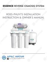
System Diagram
PRO
P
URE
DRINKING WATE R SYSTEM
Outlet water
pressure
gauge
Pump
Inlet water
pressure
gauge
Inlet water
solenoid
valve
Water in
Filter
RO membrane
Water out
Flow restrictor for pure
Flush solenoid valveNeedle valve
Drain flow meter
Drainage
Note
1.Low pressure adjuster: Lower by anticlockwise, raise by clockwise.
2.Please confirm power supply matches system's electric current, voltage, and HZ.
3.This system is automatically controlled by computer program.
People under training are best recommended to operate the system.
Operation process
Attentions Before Operation :
2
A. Pressure of Inlet Water exceeds 1.0Kg/cm .
B. Supplying electrical power accord with the need of Equipment Device,
Supplying Voltage be maintained within ± 5% as indicated scale for power
of equipment.
C. Connected tubes for permeate water and concentrate water be fairly finished.
Operating Process : ( Pre-operating have been checked )
A. Starting on-off switch.
B. Setting delay operating device (for 20 seconds) for lower pressure switch,
to protect the motor for avoiding disorder by frequent starting of operation.
C. Adjust the ratio and pressure of permeate water and concentrate water.
a. Adjusting needle valve first, scale at the ratio 1:3 for permeate water and
concentrate water, the ratio is according to the quality of inlet water, if TDS
is higher then setting concentrate water be relatively more.
b. Adjusting the inner six-angle screw of Procon head (adjusting by-pass
fluid) to accord with the production rate of RO system.
Maintenance
1. Pre-treatment Filter: According to the quality of water, usually be used for
1~3 months.
2. Check and record the actual fluid of permeate and concentrate water, if the
permeate water production is less than the normal production for 10~15%,
then RO membranes need for acid washing.
3. Check and record the pressures of inlet water and operation.
4. After replacement of Filter, press the red knob of filter housing for releasing
the remaining air in the housing.
5. Press the compelling knob (flush) on the control panel to test whether the
operation be normal.

07
PURE-PRO REVERSE OSMOSIS SYSTEM
04
PURE-PRO REVERSE OSMOSIS SYSTEM
PRO
P
URE
DRINKING WATE R SYSTEM
PRO
P
URE
DRINKING WATE R SYSTEM
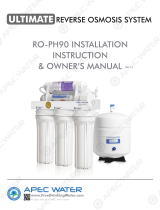
Electronic solenoid valve protector
Low pressure switch
Circuit diagram
Circuit diagram
Low pressure adjuster
High pressure
adjuster
A. Joint
B. Joint
C. Joint
AB
C
1. Low pressure adjuster:
Lower by anticlockwise,
raise by clockwise.
2. Low pressure adjuster:
Lower by anticlockwise,
raise by clockwise.
Joint direction:
1.No joint on B
2. A and B are connected to Control box
with green wire.
Installations
1. To connect 3/4" water-in PVC tubing and ball valve pipe.
2. To connect drain with 1/2" PE tubing.
3. To connect flush solenoid with 1/2" PE tubing.
4. To connect with 1/2" PE tubing to pure water tank.
5. To connect with the blue wire from control box to the floating ball switch on the
tank to control for full tank.
6. To connect power source. ( Note: voltage)
NOTE:
1. Please confirm the power specification.
2. Please confirm if the connection of pure and drain water tubing are right.
2
3. Please confirm the inner diameter of main power wire not less than 3.5mm .
4. The wire connected to full water switch and floating switch may not be used for
others.
5. Reverse flush switch is necessary for the installation of pre-filter system so RO
system could stop working for prevention from salt water to damage machine.
2
6. Please install pump before system if water-in pressure is less than 1.5 kg/cm .
7. Please clean pre-filters every week to keep the sufficient water-in supply.

05
PURE-PRO REVERSE OSMOSIS SYSTEM
06
PURE-PRO REVERSE OSMOSIS SYSTEM
PRO
P
URE
DRINKING WATE R SYSTEM
PRO
P
URE
DRINKING WATE R SYSTEM
Computer controller
The system has a automated computer controller, protection switch to detect full
water level, and 24-hour auto-flush function.
<1>Wait for 10 seconds on power supply before start the system. Flush for 1
minute, and 30 seconds flush after tank with full water. Before the next water
production, flush for 15 seconds.
<2>Setting items :
A. Water property (TDS) monitoring value setting.
B. Preset value for motor water making time.
C. Motor outlet pressure and flushing pressure steering (YES, NO).
D. Standby flushing time setting(YES, NO).
E. Fixed compulsory flushing.
<3>Use operating method :
1. Depress setting key 3 seconds to enter setting mode, the first display TDS (
000PPM)setting, then press the second display motor water making time
setting H00(YES,NO), then press the third display motor outlet pressure
and flushing pressure P=0 setting (YES, NO), than press the fourth display
full-water standby flushing F00 setting time (YES, NO).
2. To change settings, select a required mode display window, press (flush / 0
adjustment) to change settings value, automatically restore to normal
display after 5 seconds to represent setting is completed.
A. TDS vate be set from 000ppm to 100ppm.
B. Water production period set from H09 to 99. Hoo represents invalid
function.
Note: such function is to protect water tank from making water without
stopping caused from abnormal operation on switch.
C. Motor outlet pressure and flush pressure setting(P=1, 0), (P-1
represents action, P-0represents malfunction).
Note: such function is to protect when motor makes water but fails to
achieve normal pressure to cause Motor idle running and to stop water
making.
Operation direction
Computer controller
D. Under full-water standby, it can set (F01-12) hours for flush setting, and
flushing action time is 1 Minute or setting (F00) this function as
ineffective.
Note: setting time automatic flushing to prevent machine from no
operation for long time.
E. When power is off, depress setting key and strong flush key without
release, then energize to wait the display flashing with bi sound, then
release, after 13or bi sounds starts to control fixed flushing action to
conduct film pipe acid washing action, when power is turned ON / OFF it
restores to normal operation action.
F. Manual forcible flushing should require to depress strong flush key
3seconds for starting, and flushing time is 1minute.
G. Water tank Air pressure switch if not used it may cause connector JUMP.
(A) Source light flashes 20 minutes later on purifying mode.
(B) If detection is water-in
(a) Full water and source light flash on full mode.
(b) Source light flash on purifying. Purifying light shines 20 sec later.
Water-in and pump turn on.
/