Page is loading ...

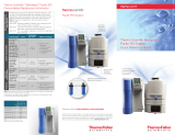
E4H-CE AND E8-CE SERIES
WATER PURIFICATION
MACHINES
3 m
3
/hr to 45 m
3
/hr
18,000 gpd to 288,000 gpd
Operation and Maintenance
Manual


INSTRUCTIONS FOR E4H-CE AND E8-CE
WATER PURIFICATION
OPERATION AND MAINTENANCE MANUAL
T
ABLE OF CONTENTS
Page
1.0 DESCRIPTION 1
1.1 Definitions 1
1.1.1 Permeate Rate 1
1.1.2 Concentrate Rate 1
1.1.3 Feed Rate 1
1.1.4 Reverse Osmosis 1
1.1.5 Membrane Elements 2
1.1.6 Clean-In-Place 2
1.1.7 Flow Control Center 2
1.1.8 Average Pressure 2
1.1.9 Concentration 2
1.1.10 Salt (Ionic) Passage 3
1.1.11 Recovery 3
1.1.12 Salt (Ionic) Rejection 3
1.2 Machine Nomenclature 5
1.3 Features 5
1.4 Specifications for E-CE Series Machines 7
1.4.1 Feed Water Specifications 8
1.4.2 Permeate Flow Rate 8
1.4.3 Concentrate Flow Rate 8
1.4.4 Pressure Range 8
1.4.5 Reverse Osmosis Membrane Element Rejection 9
2.0 INSTALLATION 10
2.1 Feed Water Requirements 10
2.2 Mounting 10
2.3 Plumbing 11
2.4 Power and Electrical Requirements 11
3.0 PREPARATION FOR START-UP 12
3.1 Pretreatment for Water Purification 12
3.2 Initial Start-Up 12
3.3 Daily Start-Up 16

Page
4.0 MACHINE OPERATION AND MAINTENANCE 17
4.1 Daily Log Sheets 17
4.2 Pre-Filter Cartridge 17
4.3 Cleaning 17
4.4 Draining Machine for Shipment 19
4.5 Membrane Element Replacement 19
4.6 Membrane Element Removal 21
5.0 FIELD INSTALLED ACCESSORIES 22
5.1 Pretreatment Shutdown 22
5.2 Permeate Flush 22
5.3 Chemical Pump 24
5.4 Clean-In-Place Installation 24
6.0 TROUBLESHOOTING 25
7.0 FORMS 33
7.1 Return Goods Authorization (RGA) 33
7.2 Start-Up Data Sheet 34
7.3 Daily Log Sheet 35
8.0 WARRANTY/GUARANTEE 36
8.1 Warranty Terms 36
8.2 Warranty Commencement Date 36
8.3 Warranty Service 36
8.4 Voidability of Warranty 37
8.5 Limitations and Exclusions 37

Page
LIST
OF
FIGURES
Figure Title
1.1 Normal Versus Cross Flow Filtration 1
1.2 Membrane Element With Interconnectors 2
1.3 Principles of Operation 3
LIST
OF T
ABLES
Figure T
itle
1.1 Flow Specifications for E-CE Reverse Osmosis Machines 7
1.2 Minimum/Maximum Boost Pressure 8
1.3 Membrane Element Specifications 9
2.4 Feed Water Requirements 10
2.5 Connections 11
1.0 DESCRIPTION
E-CE Series Reverse Osmosis (RO) machines are durable pieces of equipment, which, with prop-
er care, will last for many years. These instructions give operation and maintenance details vital
to the sustained performance of the machine. Please read completely before operating your
machine.
1.1 Definitions
The operating definitions provided below will help you further understand your machine
and this manual.
1.1.1 Permeate Rate (Product Water Rate) [Q
p
]
The Permeate Rate is the flow rate of purified water that passed through the mem-
brane element and out of the membrane element in liter/min (Lpm), cubic
meters/hour (m
3
/h), gallons/min (gpm) or gallons/hour (gph). Specified perme-
ate rates are based on a feed water temperature of 25°C (77°F). Permeate rate will
vary with temperature.
1.1.2 Concentrate Rate (Wastewater Rate) [Q
c
]
The Concentrate Rate is the flow of incoming water in Lpm or m
3
/h (gpm or gph).
1.1.3 Feed Rate [Q
f
]
The Feed Rate is the flow rate of incoming water in Lpm or m
3
/h (gpm or gph).
Feed water rate equals permeate plus concentrate rate.
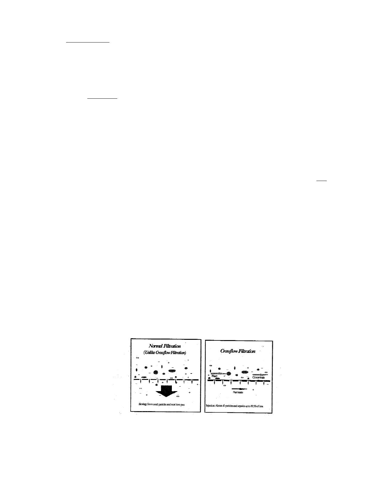
1.1.4 Reverse Osmosis
Reverse Osmosis (RO) is the separation of one component in a solution from
another component of a solution from another component by means of pressures
exerted on a semi-permeable membrane element. The feed solution is separated
into two streams, permeate and concentrate, and collected from both sides of the
membrane element.
Figure 1.1
Normal Versus Cross Flow Filtration
1

1.1.5 Membrane Elements
Membrane elements are interleaved layers of semi-permeable membrane, spacer,
and permeate carrier spiraled around a central permeate tube make up the mem-
brane element.
Figure 1.2
Membrane Element with Interconnectors
1.1.6 Clean-In-Place
The abbreviation for Clean-In-Place is CIP.
1.1.7 Flow Control Center
The Flow Control Center features a concentrate flow control valve, a recycle flow
control valve, and a pressure gauge. It is located directly behind the control enclo-
sure.
1.1.8 Average Pressure
P
AV G
(Average Pressure) = [(P
PRIMARY
+ P
FINAL
) ÷ 2]
1.1.9 Concentration
Concentration equals the Total Dissolved Solids (TDS) concentration of a solution
expressed as conductivity (µS/cm) or parts per million (ppm).
2
C
f
= Feed Concentration
C
p
= Permeate Concentration
C
c
= Concentrate Concentration
C
avg
= Average Concentration in Machine
1.1.10 Salt (Ionic) Passage
Ionic Salt Passage equals the percent of dissolved salts passed through the mem-
brane element or 100% minus rejection.
1.1.11 Recovery
Recovery equals permeate rate divided by feed rate and is expressed as a per-
centage. For example, 75% recovery means that out of a given feed rate, 75% is
produced as purified water (permeate).
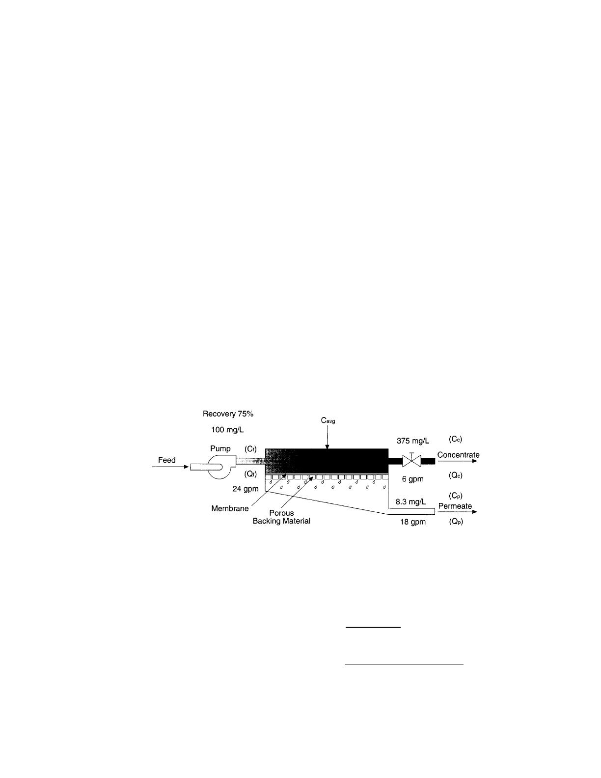
1.1.12 Salt (Ionic) Rejection
Ionic Salt Rejection equals the percent of dissolved salt rejected by the membrane
element, calculated from an average concentration over the membrane element.
An example of how to calculate salt rejection and recovery is below:
Figure 1.3
Principles of Operation
Given the system case in Figure 1.3:
3
Average Concentration (C
avg
) = [(C
f
) + (C
c
)]
2
= [(100 mg/L) + (375 mg/L)]
2
= 237.5 mg/L

4
Rejection = [(C
avg
) - (C
P
)] x 100
(C
avg
)
= [(237.5 mg/L) + (8.3 mg/L)] x 100
(237.5)
= 96.5%
Passage = (C
P
) x 100
(C
f
)
= (8.3 mg/L) x 100
(237.5)
= 3.5%
Recovery = (Q
P
) x 100
(Q
f
)
= (18 gpm) x 100
(24gpm)
= 75%
1.2 Machine Nomenclature
E-CE Series water purification machines are numbered in such a way as to indicate the
permeate flow you can expect from the machine and other specifications:
Example: RE, E8-CE-9, 400, 5, 66 - 75
1.3 Features
E4H-CE and E8-CE water purification machines have all the features necessary for safe,
continuous production of high-purity water. This assumes properly pretreated feed water
with a TDS ≤ 2000 ppm and regular operator maintenance.
· Sixty-six (66) - 75% recovery (E8-CE) or 50 -75% recovery (E4H-CE). Adjust con-
centrate and recycle flows to obtain desired recovery.
· Epoxy-coated carbon steel frame.
· Three hundred fifty (350) square foot or 85 square foot (E4H-CE) membrane ele-
ments with stainless steel (SS) membrane element housings.
5
RO E8 - CE - 9 400 5 66 - 75
Machine Type Recovery Range
(Reverse Osmosis) 66 - 75% E8-CE
50 - 75% E4H-CE
Machine Series Hertz Operation
CE-E Series 5 = 50 Hertz
(E8: 8-inch housings/membrane elements)
(E4H: 4-inch housings/membrane elements)
CE Marked 400 VAC
3-Phase Starter
Rated Permeate Flow
[9 m
3
/hour at 25°C (77°F)]

6
· Multi-stage centrifugal pump, SS construction (SS end castings and wetted parts,
Noryl* internals) on the 3 to 3 to 34m
3
/hr and AS (all Stainless Steel components)
on the 45m
3
/hr.
· Electrical package includes Programmable Logic Controller (PLC), IEC66 control
enclosure with a 24VDC control circuit, Siemens TP070 operator interface terminal,
and a Siemens S7-200 PLC.
· Twenty (20)-inch, 30-inch, or 40-in SS pre-filter housing, including 5-micron car-
tridge filters, GS05-20-XK, GX05-30-XK, GX05-40-XK for the E8-CE and 20-inch
PVC pre-filter housings, including 5-micron cartridge filters for the E4H-CE.
· Pre-filter, post-filter, primary, pump discharge, and final pressure gauges.
· Concentrate and permeate flow meters.
· Digital conductivity monitor, panel-mounted, for permeate quality monitoring with
high conductivity alarm.
· Gauges, valves, and rigid plumbing of SS or plastic.
·
Stainless Steel concentrate and recycle valves.
· External control capabilities (level control, pretreatment lockout).
· ALARMS included: low inlet pressure, high permeate pressure, high conductivity,
high pH, starter overload trip, and high temperature.
· Permeate purge capability.
·
High permeate pressure shutdown.
·
Low inlet pressure shutdown.
* Noryl is a trademark of General Electric Company.

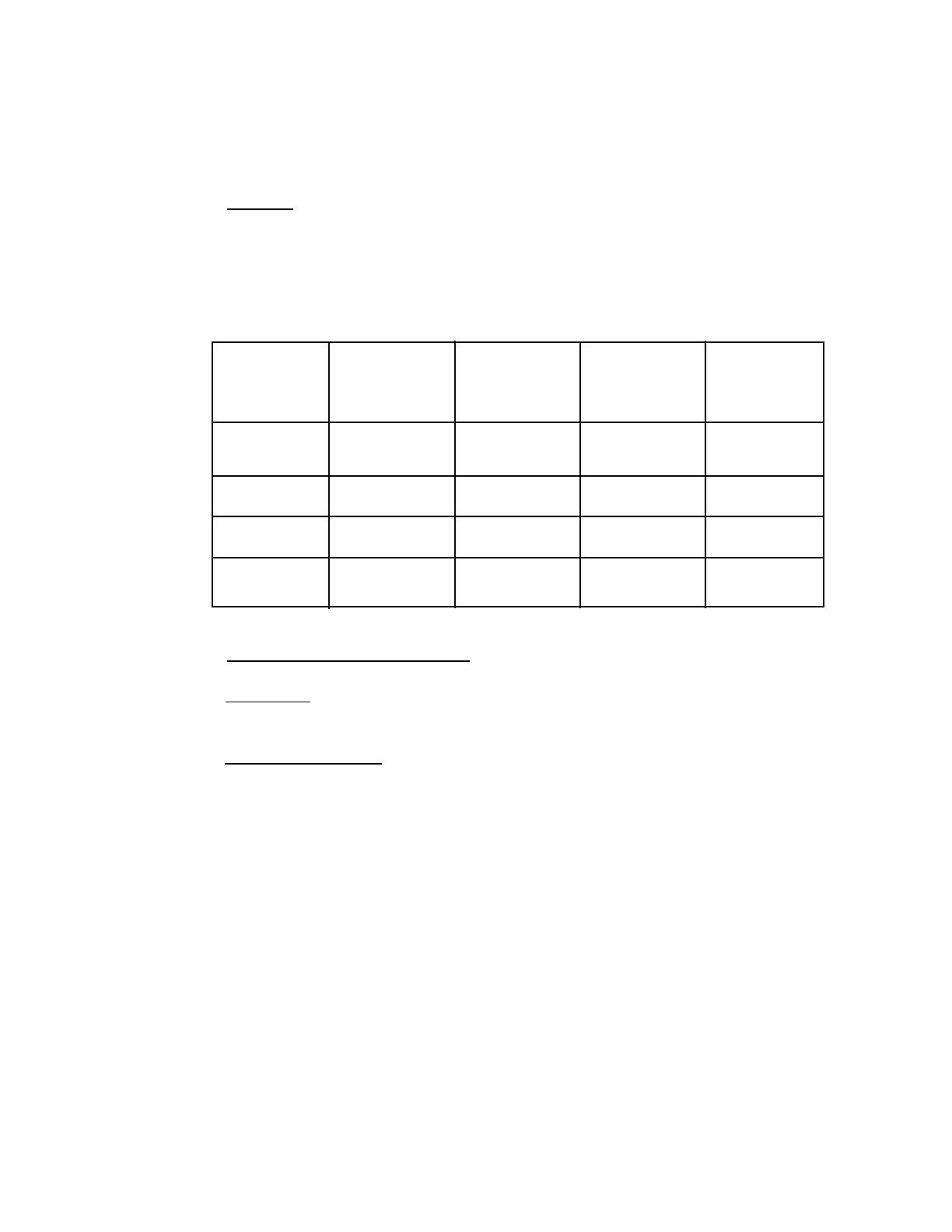
1.4 Specifications for E-CE Series Machines
The machine flow specifications listed, Table 1.1 below, are based on 25°C (77°F) and
2000 ppm NaCl.
Table 1.1
Flow Specifications for
Reverse Osmosis
E-CE Machines
7
MODEL
Recovery
Units
Permeate
Rate
Concentrate
Rate
(50-66%)
Concentrate
Rate
(75%)
Feed Rate
(50-66%)
Feed Rate
(75%)
Recycle
Rate
(55-66%)
Recycle
Rate
(75%)
E4H-CE-3
50-75%
LPM/GPM
47.4/12.5
47.4/12.5
15.8/4.2
94.7/25.0
63.1/16.7
15.1/4.0
46.6/12.3
E4H-CE-%
50-75%
LPM/GPM
78.9/20.9
78.9/20.9
26.3/7.0
157.8/41.7
105.2/27.8
0.0/0.0
46.2/12.2
E4H-CE-7
50-75%
LPM/GPM
126.3/33.4
126.3/33.4
42.1/11.1
252.5/66.7
168.4/44.5
0.0/0.0
81.5/21.5
E4H-CE-9
66-75%
LPM/GPM
151.4/40.0
75.7/20.0
50.5/13.3
227.1/60.0
201.9/53.3
68.1/18.0
93.4/24.7
E4H-CE-14
66-75%
LPM/GPM
227.1/60.0
113.6/30.0
75.7/20.0
340.7/90.0
302.8/80.0
107.3/45.0
208.2/55.0
E4H-CE-23
66-75%
LPM/GPM
378.5/100.0
189.3/50.0
126.2/33.3
567.8/150.0
504.7/133.3
56.8/15.0
119.9/31.7
1.4.1 Feed Water Specifications
The feed water requirements listed in Table 1.1 must be met to ensure quality per-
meate and extended membrane element life.
1.4.2 Permeate Flow Rate
Stated in Table 1.1 and on the machine serial number label (assumes no permeate
back pressure, 2000 mg/L Total Dissolved Solids (TDS) maximum feed concen-
tration, and rated temperature).
To estimate permeate output with back pressure, use the formula below.
Maximum permeate back pressure is 80 psig (5.5 bar).
(Specified Permeate) x [(Operating Pressure) - (Permeate Back pressure)]
(Operating Pressure)
1.4.3 Concentrate Flow Rate
Stated in Table 1.1 and factory-set as stated on the serial number label.
1.4.4 Pressure Range
The Pressure Ranges listed below (Table 2.1) are boost pressure:
Boost Pressure = [(Primary Pressure - (Post-Filter Pressure)].
Table 1.2
Minimum/Maximum (Min/Max)
Boost Pressure
8
MODEL
E4H-CE-3
E4H-CE-5
E4H-CE-7
E8-CE-9
E8-CE-14
E8-CE-23
PUMP MODEL
Tonkaflo, SS2823G-50
Tonkaflo, SS2823G-50
Tonkaflo, SS2823G-50
Tonkaflo, SS2823G-50
Tonkaflo, SS2823G-50
PRIMARY PRESSURE
RANGE bar (psi)
8.6 - 15.5 (125 - 225)
7.6 - 15.5 (110 - 225)
6.6 - 14.4 (100 - 210)
6.6 - 12.8 (95 - 185)
5.2 - 9.3 (75 - 135)

1.4.5 Reverse Osmosis Membrane Element Rejection
E8-CE RO machines use Fiberglass Reinforced Plastic (FRP). E4H-CE RO
machines use tape wrapped membrane elements. For more information, refer to
the Spare Parts List (P/N 1233377).
Table 1.3
Membrane Element
Specifications
9
Specification
Outer Cover Material
Typical Ionic Rejection (TDS)
Nominal Permeate Flow Rate
[at 7.6 bar (110 psi)]
Typical Feed Water
Temperature Range
Maximum Temperature Range
Short-Term Cleaning
Temperature
pH Range
Chlorine Tolerance
Active Membrane Area
Average Molecular Weight
Cutoff*
E4H-CE
Tape
98.0 - 99.5%
8.3 m
3
/d (2200 gpd)
10° - 29°C (50° - 85°F)
0° - 40C (32° - 104°F)
< 43°C (110°F)
3.0 - 11.0
< 0.1 ppm
7.9 m
2
(85 ft
2
)
1500 MW*
E8-CE
FRP
98.0 - 99.5%
39.8 m
3
/d (10500 gpd)
10° - 29°C (50° - 85°F)
0° - 40°C (32° - 104°F)
< 43°C (110°F)
3.0 - 11.0
< 0.1 ppm
32.5 m
2
(350 ft
2
)
1500 MW*
* The Molecular Weight (MW) cutoff is based on the pore size of membrane elements and the
nature (size/shape) of the organic molecule.

2.0 INSTALLATION
The following installation guidelines will help you install your new E-CE RO machine.
2.1 Feed Water Requirements
The following feed water requirements must be met before installing your new E-CE RO
machine to ensure quality permeate and extended membrane element life.
Table 2.4
Feed Water Requirements
2.2 Mounting
E-CE Series machines are equipped with a stand-alone frame, which supports the
machine. At least 114 cm (45-inches) of space should be allowed on each end of the
10
Temperature
Inlet Pressure
Chlorine (continuous feed)
Feed Water
Silt Density Index
(SDI)
Typical: 10 - 29°C (50° - 85°F)
Minimum: 2.1 barg (30 psig)
Maximum: 4.1 barg (60 psig)
0 ppm
For soft water [less than 1 grain per gallon
(gpg) or 17 mg/L hardness]
acceptable pH: 3.0 - 11.0
For unsoftened water (contact factory for
water analysis), acceptable pH: 5.0 - 6.0
For short-term (i.e., cleaning) acceptable
SDI range: 2 - 12
Less than or equal to 4 to minimize mem-
brane element fouling and extend cleaning
intervals. Refer to ASTM Standard
D4189
membrane element housings for removal and loading of membrane elements. If 114 cm
(45-inches) are not available, the entire membrane element housing may need to be
removed for membrane element replacement.
2.3 Plumbing
The E4H-CE and E8-CE come with flanged connections installed on all isolation valves.
Table 2.5
Connections
2.4 Power and Electrical Requirements
WARNING: BEFORE OBTAINING ACCESS TO TERMINALS, ALL SUPPLY
CIRCUITS MUST BE DISCONNECTED.
IMPOR
TANT NOTE: Motor are dual rated. Factory installed starters and
wiring are for 400VAC (380VAC). Motor starter and
motor wiring must be replaced prior to converting to lower
voltage. Custom Factory Order (CFO) based motors can
be rated at other voltages. Check motor for rating.
The E4H-CE and E8-CE machines are supplied with a single source of incoming power.
This power can be 230, 380, 415, 460, or 575 VAC. Check tag on High Voltage Enclosure
to verify which voltage is required. The power for control is transformed down from the
three-phase power at the main disconnect to 230 single-phase and then down to 24 VDC.
For each model, the motor is wired at the factory to an overload protection motor starter,
which is controlled by the panel-mounted Operator Interface Terminal (OIT).
11
MACHINE
Model
Inlet
Concentrate
Permeate
E4H-CE
All Models
40 mm
25 mm
25 mm
E8-CE
9 - 14
50 mm
40 mm
50 mm
E8-CE
17 - 23
80 mm
40 mm
50 mm
E8-CE
28 - 45
100 mm
50 mm
80 mm

3.0 PREPARATION AND START-UP
3.1 Pretreatment for Water Purification
All systems will operate most efficiently on filtered water with a pH of less than 6.5 and
a Silt Density Index (SDI) of 5 or below. If the machine is operated on higher pH water,
other forms of pretreatment may be necessary. A water analysis prior to start-up of the
machine is required. To minimize the chances of calcium carbonate, calcium sulfate, or
other salt precipitation on the membrane element, GE Osmonics evaluates each applica-
tion and water condition and makes specific recommendations to assure continuity of the
membrane element warranty. Data from the water analysis is processed with a computer
program analysis to determine if potential problems may exist. If the machine is to be run
at a different location than was originally intended, a new water analysis is required for
warranty considerations and should be sent to GE Osmonics for review and recommen-
dations for operation of the machine.
Before installing the machine, the feed water must be filtered to 5 microns.
Thin-layer composite (TLC) membrane element feed water must not contain the follow-
ing chemicals or permanent loss of rejection and/or permeate flow may
result:
Free chlorine
Formalin (until after membrane element has run for 24 hours, thereafter, 0.5% formalde-
hyde may be Used as a biocide)
Iodine compounds
Quaternary germicides
Cationic surfactants
Detergents containing non-ionic surfactants
Cleaners not approved by GE Osmonics
CAUTION
: A water softener should not regenerate while the machine is running
unless safeguards are used to be sure the machine is operated on softened
water during regeneration.
NOTE
: To control the RO operation based on water softener regeneration cycle,
wire the softener to the Pretreatment Shutdown Control circuit, as
described in Field Installed Accessories.
3.2 Initial S
tart-Up
NOTE: If your machine has the membrane elements installed in the housing, pro-
ceed to Steps below. If your machine is provided with the membrane ele-
ments in shipping boxes, you must load the membrane elements in the
housings prior to starting the machine. For membrane element loading
instructions, go to Section 4.5 (Membrane Element Installation). Once
membrane element installation is complete, return to Step 1 (below) to
continue the start-up procedure.
12

STEPS
1. Recheck the function and integrity of your pretreatment equipment. Ensure that
your water softener, activated carbon filters, and iron filters (where applicable)
have been leaked checked, back washed, and thoroughly rinsed for service before
starting up your RO unit.
2. Attach the feed water pipe to the inlet of the machine. The standard connection
fitting is a polyvinyl chloride (PVC) flanged connection. Refer to Table 2.5
(Connections) for connection sizes.
3. Check for leaks at all connection points.
4. Turn the feed water supply gradually ON and check for leaks in the inlet plumb-
ing.
NOTE
: When the machine is OFF, there should never be flow through the
machine. Flow through the machine when it is OFF can ruin the mem-
brane elements.
5. Attach discharge plumbing to permeate and concentrate outlet points and run the
tubing to the drain. The standard connection fitting is a polyvinyl chloride (PVC)
flanged connection. Refer to Table 2.5 (Connections).
6. The machine requires one high voltage power source. The motor electrical ser-
vice must be field wired directly into the motor starter on the machine. Be sure
the power to the motor starter is de-energized by turning the disconnect on the
high voltage enclosure to the OFF position. The high voltage enclosure can only
be opened while in the OFF position. Bring your motor service to terminals
labeled “T” on the motor starter. Check the voltage label to ensure you have
brought the correct voltage to the starter.
IMPOR
TANT NOTE Motors are dual rated. Factory installed starters and
wiring are rated for 400VAC (380VAC). The motor
starter and motor wiring must be replaced prior to con-
verting to a lower voltage.
7. Open your concentrate and recycle flow control valves (located behind the con-
trol enclosure).
The concentrate valve determines the amount of rejected water leaving the
machine and creates the operating pressure shown on the pressure gauge. The
recycle valve returns unused reject flow back into the inlet stream to the RO
pump. It is important to balance the operating pressure and the respective flows
of these valves to ensure that your machine is operating correctly.
13

It is also important to understand the relationship of these two valves, the pressure
gauge, and your RO pump. The pump has a fixed amount of flow produced, and
the valves are the control devices to distribute this fixed flow amount. The pres-
sure gauge is an indicator of applied membrane element pressure a the flows set
by the valves
8. Press the Fill Button on the OIT so it is in the ON position. Water should begin
to flow through the machine at this point, but the pump will not start. Allow the
machine to fill for ten (10) minutes.
9. As your machine is filling check for leaks and repair as needed.
10. Turn the ON/OFF switch, located on the High Voltage Enclosure, to the ON posi-
tion.
11. Energize the power source to the motor starter. The pump should not operate at
this point.
12. Check the rotation of the high-pressure pump:
12a Press the RO button so it is in the ON position.
After the minimum inlet pressure [0.8 bar (11.6 psi)] is established and
maintained for six (6) seconds, the high-pressure pump will start.
12b When the high-pressure pump starts, immediately press the RO button so
it is in the OFF position.
The motor should rotate clockwise while looking at the motor end of the high-
pressure pump. If the motor is not rotating clockwise, change any two of the three
leads in the motor starter and recheck rotation.
W
ARNING: ALWAYS TURN POWER OFF TO CHANGE ANY
WIRING.
CAUTION
: Operation of the pump backward, even for a short time, can cause
damage to the pump.
13. Press the RO button so it is in the ON position. The high-pressure pump will
operate and the machine will begin to build pressure.
14. As the machine is operating, watch the primary and final pressure gauges on the
instrument panel. The machine is designed to operate at approximately 7.6 bar
(110 psi).
NOTE
: Do not allow the pressure to exceed the maximum boost pressure
(P
max
) specified for your machine model (Table 1.2). If the pressure
exceeds P
max
, open the concentrate and/or recycle control valves until
the pressure gauge shows P
max
or less.
14

15. As the machine purges the air and fills with water, the pressure will gradually
increase. Water should flow through the permeate and concentrate piping, viewed
on the individual flow meters. If you do not see flow, turn the machine OFF and
return to Section 3.2 (Initial Start-Up).
16. Gradually adjust the concentrate flow control valve. As you adjust the valve,
watch the average pressure (P
avg
) and the your concentrate flow meter. Adjust the
valve until your concentrate flow meter displays the desired flow and does not
exceed P
max
. If P
max
is exceeded before the valve is completely closed, open the
recycle flow control valve one full turn, then continue to adjust the concentrate
flow valve.
17. With the concentrate flow control valve set to obtain the desired concentrate flow
and the pressure below P
max
, gradually adjust the recycle flow control valve until
P
avg
reaches 7.6 bar (110 psi). Readjust the concentrate and then the recycle
valves, if necessary.
18. Once the desired flow rate is achieved [7.6 bar (110 psi)] operating pressure, no
further valve adjustment is needed.
NOTE
: Permeate flow rates are dependent upon temperature and conditions at
your site. Contact your distributor if you have any questions.
The system is now operational.
19. Before putting the machine into final operation, continue to run the permeate and
concentrate streams to the drain for at least thirty (30) minutes
. This is done to
ensure that all the preservative have been removed from the membrane elements.
20. Connect the permeate line to the point-of-use of the permeate. Check for leaks
and ensure that you have no kinks in hoses or blockage of any plumbing on the
permeate and concentrate outlet lines.
21. Make any final adjustments for flow and pressure, according to Step 18, if need-
ed.
22. Complete and create copies of the Start-Up Log Sheet (Section 7.2). A Daily Log
Sheet (Section 7.3), including general operating conditions (pressures, flow, con-
centrations, pH, and pretreatment conditions) and routine or special maintenance
(flushing or cleaning as needed) must be kept. GE Osmonics will require these
Log Sheets if a warranty question arises.
15
/