Page is loading ...

Membrane System
User Manual
ELC – Series
ELC – 1500
w

ELC – Series User Manual
MKTF – 506-A 2 03/18
This page intentionally
left blank

ELC – Series User Manual
MKTF – 506-A 3 03/18
TABLE OF CONTENTS
INTRODUCTION ............................................................................................................ 4
SAFETY .......................................................................................................................... 5
FEEDWATER AND OPERATION SPECIFICATIONS ..................................................... 6
REJECTION, RECOVERY AND FLOW RATES ............................................................. 7
SYSTEM REQUIREMENTS AND OPERATION GUIDELINES ....................................... 8
ELECTRICAL .................................................................................................................. 9
MEMBRANE ELEMENTS ............................................................................................. 10
SYSTEM IDENTIFICATION .......................................................................................... 11
MEMBRANE INSTALLATION, REMOVAL AND REPLACEMENT ................................ 13
INITIAL START–UP ...................................................................................................... 17
OPERATING DO’S AND DON’TS ................................................................................. 18
RO SHUT–DOWN PROCEDURE ................................................................................. 18
PRODUCT SPECIFICATIONS ...................................................................................... 19
OPERATING LIMITS .................................................................................................... 20
OPERATION AND MAINTENANCE .............................................................................. 21
FLUSHING THE SYSTEM ............................................................................................ 22
PREPARING UNIT FOR STORAGE AND SHIPMENT ................................................. 23
TROUBLESHOOTING .................................................................................................. 24
OPERATING LOG ........................................................................................................ 26
TEMPERATURE CORRECTION FACTORS FOR MEMBRANE ................................... 27
SERVICE ASSISTANCE ............................................................................................... 28
SYSTEM DRAWINGS, FLOW DIAGRAMS ................................................................... 29
ELECTRICAL SCHEMATIC .......................................................................................... 32
SYSTEM WARRANTY .................................................................................................. 33

ELC – Series User Manual
MKTF – 506-A 4 03/18
INTRODUCTION
Your ELC – Series Reverse Osmosis System is a durable piece of equipment which, with
proper care, will last for many years. This User Manual outlines installation, operation,
maintenance and troubleshooting details vital to the sustained performance of your
system.
If your system is altered at the site of operation, or if the feedwater conditions change,
please contact your local dealer or distributor to determine the proper recovery for your
application.
IN ORDER TO MAINTAIN THE MANUFACTURER’S WARRANTY, AN
OPERATING LOG MUST BE MAINTAINED AND COPIES WILL NEED TO BE
SENT TO YOUR LOCAL DEALER OR DISTRIBUTOR FOR REVIEW.
PRIOR TO OPERATING OR SERVICING THE REVERSE OSMOSIS SYSTEM,
THIS USER MANUAL MUST BE READ AND FULLY UNDERSTOOD. KEEP THIS
AND OTHER ASSOCIATED INFORMATION FOR FUTURE REFERENCE AND
FOR NEW OPERATORS OR QUALIFIED PERSONNEL NEAR THE SYSTEM.

ELC – Series User Manual
MKTF – 506-A 5 03/18
SAFETY
The Safety section of this User Manual outlines the various safety headings used throughout
this manual’s text and are enhanced and defined below:
INDICATES STATEMENTS THAT ARE USED TO IDENTIFY CONDITIONS
OR PRACTICES THAT COULD RESULT IN EQUIPMENT OR OTHER
PROPERTY DAMAGE.
INDICATES STATEMENTS THAT ARE USED TO IDENTIFY CONDITIONS
OR PRACTICES THAT COULD RESULT IN INJURY OR LOSS OF LIFE.
FAILURE TO FOLLOW WARNINGS COULD RESULT IN SERIOUS INJURY
OR EVEN DEATH.
DO NOT, UNDER ANY CIRCUMSTANCES, REMOVE ANY CAUTION,
WARNING OR OTHER DESCRIPTIVE LABELS FROM THE SYSTEM.
PLEASE READ THE ENTIRE MANUAL BEFORE PROCEEDING WITH
THE INSTALLATION AND START–UP. FAILURE TO FOLLOW
INSTRUCTIONS OR OPERATING PARAMETERS MAY LEAD TO THE
PRODUCT’S FAILURE, WHICH CAN CAUSE PROPERTY DAMAGE
AND/OR PERSONAL INJURY.
•
DO NOT USE WHERE THE WATER IS MICROBIOLOGICALLY UNSAFE OR OF
UNKNOWN QUALITY WITHOUT ADEQUATE DISINFECTION BEFORE OR
AFTER THE SYSTEM.
•
PRE–TREATMENT MUST BE SUFFICIENT TO ELIMINATE CHEMICALS,
ORGANICS OR INORGANICS THAT COULD ATTACK THE MEMBRANE
MATERIAL.
•
ALWAYS DISCONNECT THE ELECTRICAL POWER AND SHUT OFF THE
FEEDWATER BEFORE WORKING ON THE UNIT.
•
NEVER ALLOW THE PUMP TO RUN DRY.
•
NEVER ALLOW THE UNIT TO FREEZE OR OPERATE WITH A FEEDWATER
TEMPERATURE ABOVE 85°F.

ELC – Series User Manual
MKTF – 506-A 6 03/18
FEEDWATER AND OPERATION SPECIFICATIONS
Nothing has a greater effect on a reverse osmosis system than the feedwater quality.
IT IS VERY IMPORTANT TO MEET THE MINIMUM FEEDWATER
REQUIREMENTS. FAILURE TO DO SO WILL CAUSE THE
MEMBRANES TO FOUL AND VOID THE MANUFACTURER’S
WARRANTY.
OPERATING LIMITS*
Operating Parameters:
Feed Temperature
40 – 85°F
System Inlet Pressure
40 – 60 psi
Maximum Operating Pressure (at 77°F)
90 psi
Feedwater Requirements:
Maximum SDI Rating
< 3
Maximum Turbidity
1 NTU
Maximum Free Chlorine and/or Chloramines
0 PPM
PH (continuous)
2 – 11
PH (cleaning for 30 minutes)
1 – 13
*If any of the feedwater parameters are not within the limits given, consult your local dealer or distributor for
assistance.
HIGHER TDS AND/OR LOWER TEMPERATURES WILL REDUCE THE SYSTEM’S
PRODUCTION.

ELC – Series User Manual
MKTF – 506-A 7 03/18
REJECTION, RECOVERY AND FLOW RATES
ELC – Series Reverse Osmosis Systems are designed to produce permeate water at
the capacities indicated by the suffix in the system’s name under the conditions listed
above. For example, the ELC – 750 system produces 750 gallons per day of
permeate water at the listed operating test conditions.
The amount of total dissolved solids (TDS) rejected by the membrane is expressed
as a percentage. For example, a 98.5% rejection rate means that 98.5% of total
dissolved solids do not pass through the membrane. To calculate the percentage of
rejection, use the following formula:
% Rejection = [(Feed TDS – Product TDS) / Feed TDS] x 100
Example:
98.5% = [(550 – 8.25) / 550] x 100
ALL TDS FIGURES MUST BE EXPRESSED IN THE SAME UNITS, TYPICALLY
PARTS PER MILLION (PPM) OR MILLIGRAMS PER LITER (MG/L).
ELC – Series Reverse Osmosis Systems are designed to reject up to 98.5% NaCl,
unless computer projections have been provided or stated otherwise.
The amount of permeate water recovered for use is expressed as a percentage. To
calculate the percentage of recovery, use the following formula:
% Recovery = (Product Water Flow Rate / Feed Water Flow Rate) x 100
Example:
50% = (1.02 / 2.04) x 100
ALL FLOW RATES MUST BE EXPRESSED IN THE SAME UNITS, TYPICALLY
GALLONS PER MINUTE (GPM).

ELC – Series User Manual
MKTF – 506-A 8 03/18
SYSTEM REQUIREMENTS AND OPERATION GUIDELINES
PLUMBING
The membranes and high pressure pumps used on ELC – Series systems require a
continuous flow of water with a minimum feed pressure of 40 psi, not to exceed 60 psi.
FEEDWATER CONNECTION
1. Locate the 1/2” quick connect tube fitting labeled “feed” on the left side of the frame.
2. Attach the inlet tubing to the 1/2” feedwater inlet.
3. Be certain that all of the components of the feedwater are soluble at the
concentrations attained in the system.
FEED LINE MUST BE A MINIMUM OF 1/2” INCH.
PERMEATE (PRODUCT WATER) CONNECTION
Locate the 3/8” quick connect tube fitting on the left side of the frame labeled “permeate”.
Attach 3/8” tubing and connect it to the point of use. This system is equipped with a
permeate high pressure switch and is designed to fill a pressurized storage tank. When
using a pressurized storage tank locate the 3/8” quick connect tubing fitting labeled “holding
tank” on the right side of the frame. Attach 3/8” tubing and connect it to the pressurized
storage tank. Ensure that the permeate water can flow freely with no backpressure.
Backpressure can cause irreversible damage to the membrane elements. The permeate
line can be run to the point of use with Polypropylene or other FDA approved materials so
the material being used does not dissolve into the permeate water.
THE PH OF THE REVERSE OSMOSIS PERMEATE WATER WILL
TYPICALLY BE 1 OR 2 PH UNITS LOWER THAN THE FEEDWATER PH.
A LOW PH CAN BE VERY AGGRESSIVE TO SOME PLUMBING
MATERIALS SUCH AS COPPER PIPING.
CONCENTRATE (WASTE WATER) CONNECTION
Locate the 3/8” quick connect tube fitting labeled “concentrate”, and attach 3/8” tubing
to a drain. Run the concentrate line to an open drain in a free and unrestricted manner
(no backpressure).
ANY RESTRICTIONS OR BLOCKAGE IN THE DRAIN LINE CAN CAUSE
BACKPRESSURE, WHICH WILL INCREASE THE SYSTEM’S
OPERATING PRESSURE. THIS CAN RESULT IN DAMAGE TO THE
SYSTEM’S MEMBRANES AND COMPONENTS.

ELC – Series User Manual
MKTF – 506-A 9 03/18
ELECTRICAL
The motor used on the ELC is available in 110 VAC 60 Hertz 1 Phase. Each ELC – Series system is
equipped with an eight–foot electrical cord with a three pronged electrical plug.
Ensure that the electrical circuit supplying the system is compatible with the requirements of the specific
ELC – Series model you are installing.
IT IS RECOMMENDED THAT A LICENSED ELECTRICIAN WIRE YOUR SYSTEM IN
ACCORDANCE WITH LOCAL AND NATIONAL ELECTRICAL CODES (NEC).
TO REDUCE THE RISK OF ELECTRICAL SHOCK, THE INCOMING POWER
SUPPLY MUST INCLUDE A PROTECTIVE EARTH GROUND.
ELC – Series systems are not typically controlled with a liquid level switch in a storage tank. The liquid
level switch turns the system on when the water level in the tank drops, and off when the tank is full.
Should you choose a liquid switch(s) for your application it can be obtained by your local dealer or
distributor. If a liquid level switch is to be used, install it at this time.
PRE–FILTRATION
ELC – Series systems are supplied with a 5–micron sediment filter and a 10 micron carbon block filter
(ELC – 750 only). Change the cartridge once a month or when a 10–15 psi differential exists between
the two pre–filter gauges.
THE SYSTEM MUST BE OPERATED ON FILTERED WATER ONLY.
PUMP
The pump type used on the ELC – Series systems is rotary vein pump. If any damage occurs to your
system’s pump, a re–build kit may be available. Contact your local dealer or distributor and inform
them of your system and pump model.
MOUNTING
The free standing system should be bolted down or securely fastened in compliance with local
regulation standards.

ELC – Series User Manual
MKTF – 506-A 10 03/18
MEMBRANE ELEMENTS
ELC – Series Reverse Osmosis Systems are equipped with Thin Film Composite (TFC) HF5
– Ultra Low Energy membranes, unless otherwise specified. General membrane element
performance characteristics are listed below.
HF5 – Ultra Low Energy Membranes
▪ Membrane Type: Polyamide Thin – Film Composite
▪ pH Range, Short Term Cleaning (30 Min.): 1 – 13
▪ Maximum Operating Temperature: 113°F
▪ Maximum Feed Silt Density Index (SDI): 5
▪ Maximum Operating Pressure: 400 psi
▪ Chlorine Tolerance: 0 ppm
▪ pH Range, Continuous Operation*: 2 – 11
▪ Maximum Feed Flow Rate (gpm): 2.5” = 6; 4.0” = 16
*Maximum temperature for continuous operations above pH10 is 95°F (35°C).
Product Specifications
Part Number
Description
Applied
Pressure (psi)
Permeate Flow
Rate (gpd)
Nominal Salt
Rejection (%)
209175
HF5 – 3018
80
750
98.5%
Warranty Evaluation Test Conditions: Permeate flow and salt rejection based on the following test conditions – 550 ppm, filtered and dechlorinated municipal tap water, 77°F / 25°C, 15% recovery
and the specified operating pressure. Minimum salt rejection is 96%. Permeate flows for warranty evaluation may vary +/-20%. Maximum pressure drops at 13 psi / 0.9 bar.
Dimensions inch / mm
Description
A
B
C
D
HF5 – 3018
19.75
0.98
0.745
3.00
Proper start–up of reverse osmosis water treatment systems is essential to prepare the membranes for operating service and to prevent membrane damage due to
overfeeding or hydraulic shock. Before initiating system start–up procedures, membrane pretreatment, loading of the membrane elements, instrument calibration
and other system checks should be completed.
Avoid any abrupt pressure or cross–flow variations on the spiral elements during start–up, shutdown, cleaning or other sequences to prevent possible membrane
damage. During start–up, a gradual change from a standstill to operating state is recommended as follows:
▪ Feed pressure should be increased gradually over a 30 – 60 second time frame.
▪ Cross–flow velocity at set operating point should be achieved gradually over 15 – 20 seconds.
▪ Permeate obtained from first hour of operation should be discarded.
▪ Maximum pressure drops across an entire pressure vessel (housing) is 30 psi / 2.1 bar.
▪ Avoid static permeate–side backpressure at all times.
Under certain conditions, the presence of free chlorine, chloramines and other oxidizing agents will cause premature membrane failure. Since oxidation damage is
not covered under warranty, the manufacturer recommends removing all oxidizing agents by pretreatment prior to membrane exposure. Please contact the
manufacturer or your supplier for more information.
Do not use this initial permeate for drinking water or food preparation. Keep elements moist at all times after initial wetting. To prevent biological growth during
prolonged system shutdowns, it is recommended that membrane elements be immersed in a preservative solution. Rinse out the preservative before use. For
membrane warranty details, please contact the manufacturer or your supplier for more information.
If operating limits and guidelines given in this product specification sheet are not strictly followed, the warranty will be null and void. The customer is fully responsible
for the effects of incompatible chemicals and lubricants on elements. Use of any such chemicals or lubricants will void the warranty. These membranes may be
subject to drinking water application restrictions in some countries: please check the application status before use and sale. The use of this product in and of itself
does not necessarily guarantee the removal of cysts and pathogens from water. Effective cyst and pathogen reduction is dependent on the complete system design
and on the operation and maintenance of the system.
No freedom from infringement of any patent owned by the manufacturer or others is to be inferred. Because use conditions and applicable laws may differ from one
location to another and may change with time, customer is responsible for determining whether products and the information in this document are appropriate for
customer’s use and for ensuring that customer’s workplace and disposal practices are in compliance with applicable laws and other governmental enactments. The
claims made may not have been approved for use in all countries. The manufacturer assumes no obligation or liability for the information in this document. NO
WARRANTIES ARE GIVEN; ALL IMPLIED WARRANTIES OF MERCHANTABILITY OR FITNESS FOR A PARTICULAR PURPOSE ARE EXPRESSLY
EXCLUDED.

ELC – Series User Manual
MKTF – 506-A 11 03/18
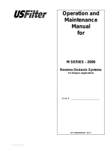
SYSTEM IDENTIFICATION
Figure 1

ELC – Series User Manual
MKTF – 506-A 12 03/18
SYSTEM IDENTIFICATION
ITEM
NO.
AXEON DESCRIPTION
AXEON
PART
NO.
MODEL(s)
1
CARTRIDGE, SEDIMENT, POLYPRO, 2.5" x 20", 5 MIC, SDF–25–2005
200626
750 - 1500
2
CARTRIDGE, CARBON, BLOCK, 2.5" x 20", 10 MIC, CBF–25–2010
200659
750
3
METER, FLOW, PM, 0.2–2 GPM, 1/2" MNPT x 1/2" MNPT, AXEON
200897
750 - 1500
4
GAUGE, PM, GLY FILL, 0–300 PSI/BAR, 2.5" DIA, 1/4" MNPT, AXEON
200904
750 - 1500
5
SWITCH, PRESSURE, LOW, N/O, 15–30 PSI, 1/4" FNPT
200906
750 - 1500
6
SWITCH, PRESSURE, HIGH, N/C 40–60, 1/4" FNPT
200907
750 - 1500
7
VALVE, CHECK, ACETAL, 3/8" QC x 3/8" QC, JG
200962
750 - 1500
8
METER, TDS, INLINE, DM–2, 1/2"QC, HM DIGITAL
203385
750 - 1500
9
GAUGE, PM, GLY FILL, 0–100 PSI/BAR, 2.5" DIA, 1/4" MNPT, AXEON
204165
750 - 1500
10
VALVE, SOLENOID, N/C, UL, 110V, 1/2" FNPT, 3 METER CORD, GC
204909
750 - 1500
11
METER, FLOW, PM, 1–5 GPM, SS VALVE, 1/2" MNPT x 1/2" MNPT,
AXEON
205104
750 - 1500
12
MEMBRANE, HF5, 3018, DRY, AXEON
209175
750 - 1500
13
METER, FLOW, PM, 85 GPH, 304 SS VALVE, 1/2" MNPT x 1/2" MNPT
209246
750 - 1500
14
STAND, FRAME, STEEL, WHITE, LC–SERIES, 20"
209373
750 - 1500
15
HOUSING FILTER, WHT/WHT, 2.5" x 20", SGL O–RING, NPR, 3/8"
FNPT
209678
750 - 1500
16
PUMP, VANE, BRASS, BYPASS, 2.3 GPM, 401, FLUID–O–TECH
207663
750
16
PUMP, VANE, BRASS, BYPASS, 3 GPM, 601, FLUID–O–TECH
207664
1500
17
MOTOR, CARBONATOR, 1/3 HP, 110/220V 50/60HZ, 48Y,
MARATHON
200808
750
17
MOTOR, CARBONATOR, 1/2 HP, 110/220V 50/60HZ, 48Y,
MARATHON
200809
1500

ELC – Series User Manual
MKTF – 506-A 13 03/18
MEMBRANE INSTALLATION, REMOVAL AND REPLACEMENT
Installation and replacing membranes in the pressure vessels is an easy process if you
have the proper information and tools at hand. Please refer to the following instructions
when removing and replacing membrane elements:
ALL PRESSURE GAUGES MUST READ ZERO BEFORE PROCEEDING.
BEFORE ATTEMPTING, DISCONNECT THE POWER FROM THE
SYSTEM AND BLEED ALL WATER PRESSURE FROM THE SYSTEM.
1. Disconnect the tubing from the bottom of the membrane housing. Unscrew the
membrane from the system.
2. Remove the replacement membrane element(s) from the shipping box; the
membrane(s) should be contained within a plastic bag.
WEAR GLOVES FOR THE FOLLOWING STEPS IN ORDER NOT TO
CONTAMINATE THE MEMBRANE.
3. Cut the bag open as close as possible to the seal at one end of the bag, so the
bag may be re–used if necessary.
4. Make sure that all parts are clean and free from dirt. Examine the brine seal,
and permeate tube for nicks or cuts.
5. Flow directions should be observed for installation of each element into their
respective pressure vessels.

ELC – Series User Manual
MKTF – 506-A 14 03/18
REPLACING THE MEMBRANE ELEMENT:
THE BRINE SEAL MUST BE IN THE CORRECT POSITION FOR EACH MEMBRANE
ELEMENT HOUSING. THE BRINE SEAL IS A RUBBER SEAL THAT PROTRUDES ON ONE
SIDE OF THE MEMBRANE AND IS ALWAYS ON THE FEED SIDE OF THE MEMBRANE
ELEMENT. FOR ELC – SERIES REVERSE OSMOSIS SYSTEMS THE BRINE SEAL
SHOULD BE ON THE TOP SIDE OF THE MEMBRANE HOUSINGS.
1. Disconnect the tubing from the bottom of the membrane housing. Unscrew the
membrane housing from the system.
2. Remove one membrane element at a time from the pressure vessels, from the
top of each housing. Long nose pliers may be necessary to pull the old
membrane element out of the membrane element housing.
3. Lubricate the brine seal and o–rings with a non–petroleum based lubricant, such
as Dow Corning
®
111. Do not use a petroleum–based lubricant.
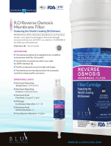
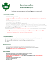
4. Install membranes with brine seal location depicted in Figure 2, on Page 15 for
ELC – 1500 or Figure 3, page 16, for ELC – 750.
5. With a smooth and constant motion, push the membrane element into the
housing.
6. Screw the membrane housing back onto the system and reattach the tubing.
7. Reconnect any fittings that may have been disconnected when the membrane
pressure vessels were disassembled.
8. To start–up the system, please refer to the Initial Start–Up section of this User
Manual.
THE MEMBRANES MUST BE FLUSHED FOR AT LEAST 30 MINUTES TO
REMOVE THE PRESERVATIVE FROM THE MEMBRANE. DISCARD ALL OF THE
PERMEATE, WHICH IS PRODUCED DURING THE FLUSH PERIOD.

ELC – Series User Manual
MKTF – 506-A 15 03/18
Figure 2

ELC – Series User Manual
MKTF – 506-A 16 03/18
Figure 3

ELC – Series User Manual
MKTF – 506-A 17 03/18
INITIAL START–UP
Carefully inspect your system before initial start–up. Check that all plumbing and electrical
connections are not loose or have not come undone during shipment.
Direct the permeate water line to drain for this procedure.
1. Fully open the concentrate valve by turning it counter–clockwise.
(#12, Figure 1, Page 11)
2. Fully close the concentrate recycle valve by turning it clockwise.
(#14, Figure 1, Page 11)
3. Plug the RO system in and adjust the concentrate (waste) valve and recycle valve to
the designed flow and pressure.
4. Inspect the system for leaks.
5. Allow the system to run 30 minutes to flush the preservative solution from the system.
6. After 30 minutes, shut down the system.
7. Re–direct the permeate water back to the tank and then turn the system back on.
8. Record the readings daily for a week; after one week record the readings once a
week.

ELC – Series User Manual
MKTF – 506-A 18 03/18
OPERATING DO'S AND DON'TS
DO:
• Change the cartridge filters regularly.
• Monitor the system and keep a daily log.
• Run the system as much as possible on a continuous basis.
• Adjust the system recovery to the recommended value.
• Always feed the pump with filtered water.
DON’T
• Permit chlorine to enter or be present in the feedwater.
• Shut down the system for extended periods.
• Operate the system with insufficient feed flow.
• Operate the pump dry.
RO SHUT–DOWN PROCEDURE
1. Purge system. See Initial Start–up instructions.
2. Turn off feed supply water from system.
3. Unplug the system power cord from wall.
4. When the unit is ready to restart please follow the initial start–up procedures. The
permeate line should be diverted to drain for 30 minutes.
If the RO unit is to be shut down for an extended period of time, a membrane preservative
should be used to preserve the membranes. See Preparing Unit for Storage or Shipment
instructions.

ELC – Series User Manual
MKTF – 506-A 19 03/18
PRODUCT SPECIFICATIONS
Models
ELC – 750
ELC – 1500
Design
Configuration
Single Pass
Single Pass
Feedwater Source
†
TDS up to 1,000
TDS up to 1,000
Nominal Recovery Rate
Up to 65%
Up to 75%
Rejection and Flow Rate
†††
Nominal Salt Rejection
98.5%
98.5%
Permeate Flow Rate
0.52 gpm
1.04 gpm
Concentrate Flow Rate
(minimum)
1.7 gpm
1.7 gpm
Concentrate Recycle Flow Rate
Up to 85 gph
Up to 85 gph
Connections
Feed
1/2” QC
1/2” QC
Permeate
3/8” QC
3/8” QC
Concentrate
3/8” QC
3/8” QC
Membranes
Membranes Per Vessel
1
1
Membrane Quantity
1
2
Membrane Size
3018
3018
Vessels
Vessel Array
1
1:1
Vessel Quantity
1
2
Pumps
Pump Type
Rotary Vane 401 Low Lead
Brass
Rotary Vane 601 Low Lead
Brass
Motor HP
1/3 HP
1/2 HP
RPM at 60 HZ
1725
1725
System Electrical
Standard Voltage + Amp Draw
110V 1PH 50/60 HZ
6.6**
110V 1PH 50/60 HZ
8.2**
System Dimensions
Approximate Dimensions*
(L x W x H)
17” x 13” x 34”
17” x 13” x 34”
Approximate Weight
50 lbs.
60 lbs.
Warranty Evaluation Test Conditions: Permeate flow rates and salt rejection based on the following test conditions – 550 ppm, filtered
and dechlorinated municipal tap water, 77°F / 25°C, 15% recovery, 7.0 pH and the specified operating pressure for membrane element type.
Data taken after 60 minutes of operation.
* Does not include operating space requirements.
** Varies with motor manufacturer.

ELC – Series User Manual
MKTF – 506-A 20 03/18
Operating Limits
††
Design Temperature
77°F
Maximum Turbidity
1
Maximum Feed Temperature
85°F
Maximum Free Chlorine (ppm)
0
Minimum Temperature
40°F
Maximum TDS (ppm)
1,000
Maximum Ambient Temperature
120°F
Maximum Hardness (gpg)
1
Minimum Ambient temperature
40°F
Maximum PH (continuous)
11
Maximum Feed Pressure
60
Minimum PH (continuous)
2
Minimum Feed Pressure
40
Maximum PH (cleaning 30 minutes)
13
Maximum Operating Pressure
90
Minimum PH (cleaning 30 minutes)
1
Maximum SDI Rating
<3
† Low temperatures and feedwater quality, such as high TDS levels will significantly affect the systems production capabilities and
performance. Computer projections must be run for individual applications which do not meet or exceed minimum and maximum operating
limits for such conditions.
†† System pressure is variable due to water conditions. Permeate flow will increase at a higher temperature and will decrease at a lower
temperature.
††† Product flow and maximum recovery rates are based on feedwater conditions as stated above. Do not exceed recommended
permeate flow.
Design conditions are not identical to test conditions, please contact the manufacturer or your supplier for more information.
Proper start – up of reverse osmosis water treatment systems is essential to prepare the membranes for operating service and to prevent
membrane damage due to overfeeding or hydraulic shock. Before initiating system start – up procedures, membrane pretreatment,
loading of the membrane elements, instrument calibration and other system checks should be completed.
Avoid any abrupt pressure or cross–flow variations on the spiral elements during start–up, shutdown, cleaning or other sequences to
prevent possible membrane damage. During start–up, a gradual change from a standstill to operating state is recommended as follows:
▪ Feed pressure should be increased gradually over a 30 – 60 second time frame.
▪ Cross – flow velocity at set operating point should be achieved gradually over 15 – 20 seconds.
▪ Permeate obtained from first hour of operation should be discarded.
▪ Maximum pressure drops across an entire pressure vessel (housing) is 30 psi / 2.1 bar.
▪ Avoid static permeate–side backpressure at all times.
Under certain conditions, the presence of free chlorine, chloramines and other oxidizing agents will cause premature membrane failure.
Since oxidation damage is not covered under warranty, the manufacturer recommends removing all oxidizing agents by pretreatment prior
to membrane exposure. Please contact the manufacturer or your supplier for more information.
Do not use the initial permeate for drinking water or food preparation. Keep elements moist at all times after initial wetting. To prevent
biological growth during prolonged system shutdowns, it is recommended that membrane elements be immersed in a preservative
solution. Rinse out the preservative before use. For membrane warranty details, contact the manufacturer or your supplier for more
information.
If operating limits and guidelines given in this product specification sheet are not strictly followed, the warranty will be null and void. The customer is
fully responsible for the effects of incompatible chemicals and lubricants on elements. Use of any such chemicals or lubricants will void the warranty.
These membranes may be subject to drinking water application restrictions in some countries: check the application status before use and sale. The
use of this product in and of itself does not guarantee the removal of cysts and pathogens from water. Effective cyst and pathogen reduction is
dependent on the complete system (solution) design and the operation and maintenance of the system.
No freedom from infringement of any patent owned by the manufacturer or others is to be inferred. Because use conditions and applicable
laws may differ from one location to another and may change with time, Customer is responsible for determining whether products and the
information in this document are appropriate for customer’s use and for ensuring that customer’s workplace and disposal practices are in
compliance with applicable laws and other governmental enactments. The claims made may not have been approved for use in all
countries. The manufacturer assumes no obligation or liability for the information in this document. NO WARRANTIES ARE GIVEN; ALL
IMPLIED WARRANTIES OF MERCHANTABILITY OR FITNESS FOR A PARTICULAR PURPOSE ARE EXPRESSLY EXCLUDE.
/