Page is loading ...

ULTIMATE REVERSE OSMOSIS SYSTEM
INSTALLATION INSTRUCTION
& OWNER’S MANUAL
All Rights Reserved © APEC Water Systems
www. FreeDrinkin gWater.com
Ver 4.0
All
Rig
h
ts
R
e
s
erve
d
© ©
APEC
Wa
ter
S
ystems
www
.F
reeD
r
r
i
i
n
n
kk
i
i
i
n
n
gW
a
t
er
.com
r
r
Ver 4.
0


Please keep this Owner’s Manual for future reference.
It contains useful information on how to maintain and care for your
APEC Reverse Osmosis water filter system.
TABLE OF CONTENT
1. Installation:
Preparation ................................................................... page 1
Filter housings assembly ................................................. page 5
Feed water connection .................................................... page 6
Drain saddle connection ................................................ page 10
Faucet mounting ............................................................ page 12
Connecting the whole system ......................................... page 13
2. Maintenance:
Filter change schedule & instructions ............................. page 18
3. Owner’s Manual - RO Basics:
System flow diagram ...................................................... page 23
Input water pressure: most important factor ................... page 24
TDS meter: testing your water quality ............................. page 24
Tank volume & delivery pressure ..................................... page 25
Misc. topics .................................................................... page 26
4. Trouble-shoot Guide:
RO Head diagram .......................................................... page 28
Humming noise ............................................................... page 29
No water at dispensing faucet ......................................... page 29
System slow shut-off ....................................................... page 31
TDS level higher than normal ......................................... page 33
Filter housing is leaking .................................................. page 34
Tank ball valve is leaking ................................................ page 35
Pure water still taste like Tap water ................................. page 35
Air bubble in cup or bottle when filling ........................... page 35
5. Other Information:
AirGap Faucet Installation ............................................. page 36
6. Warranty ........................................................................... page 38
Please keep this
OO
O
ww
n
n
n
er’s Manual
f
or
f
uture
r
r
e
e
f
f
erence.
It contains use
f
ul in
f
ormation on how to maintain and care
f
or
y
our
A
PEC Reverse Osmosis water
f
ilter system
.
TA
BLE OF CO
N
TE
TE
NTNT
N
1.
1.
I
n
s
t
a
ll
a
ti
o
n
:
Preparat
i
on ........................
..
..
..
..
..
..
.
..
................................. page
1
Filter housings assembly .
..
.
....
..
..
..
...................................... page
5
Feed water connection
..
..
....
..
.
..
.
.......................................... page
6
Dr
a
in
sadd
l
e
co
nn
e
ct
t
io
i
n
n
n
.
..
.
............................................. pa
ge
e
10
10
Faucet mount
i
ng
.
..
.
..
.
..
..
..
.
..
................................................. pa
ge
ge
1212
C
onnecti
ng
the
w
w
hoho
le
le
s
ys
tem .........................................
pa
ge
ge
13
13
1
2
.
M
ain
te
e
na
na
n
nc
nc
e:
e:
Filt
er
r
cc
haha
ha
ngng
e
e
schedule & instructions ............................. page 1
8
3
.
O
wner’s Manual - RO Basics:
System
f
low diagram .........................
..
.
..
.
.
..
..
..
..
................... page
23
Input water pressure: most importa
nt
nt
fafa
ctct
o
or
................... page
24
T
DS meter: testing your water
qu
u
alal
al
it
it
y
y
.
.
.
..
.......................... page
24
T
ank volume & deliver
y
pr
essu
re
re
e
..
..
..
.
...............................
TT
pa
ge
2
5
M
isc. topics ......................
..
..
..
..
..
.
..
...................................... page 2
6
4
.
T
ro
ub
le
-s
ho
ot
G
ui
de
:
:
TT
RO Head di
ag
ra
m
m
.
.
..
.
..
.
..
...................................................
pa
a
gege
28
28
2
Humming no
is
s
s
e e
e
.
..
.
..
..
.
.........................................................
pa
pa
gege
29
No water at
di
di
sp
sp
ensing
f
aucet .........................................
pa
pa
p
ge
29
System slo
w
w
sh
sh
u
ut
-o
ff
..
..
..
..
..
..
..
..
..
..
..
..
..
..
..
..
..
..
..
..
..
..
..
..
..
..
.
..
..
..
.
..
..
.
.
pa
pa
ge
31
TD
D
S
S
le
le
veve
v
l
l
hi
i
g
gh
er than normal ............................
..
..
.
..
....
..
..
.
..
..
.
..
page
33
Fi
ltlt
er
er
hh
ouou
o
s
si
ng is leaking .......................................
....
....
..
..
..
..
.
..
. page
34
Ta
a
nknk
b
b
alal
ll
v
va
lve is leaki
ng
................................................
pa
ge
3
5
Pu
re
e
w
w
a
at
er still taste like Tap water ................................. page
35
A
ir bubble in cup or bottle when
f
illing ........................... page 3
5
5
.
O
th
e
r In
fo
rm
a
ti
o
n:
A
irG
ap
Faucet Installation .............................................
pa
ge
36
6
.
W
arranty
W
W
.............................
.
..
..
..
..........................................
page
38

1
Thank you for choosing APEC reverse osmosis systems.
You now own the finest water filter in America.
Please read and become familiar with instructions and parts needed before proceeding with the
installation.
BEFORE INSTALLATION:
Inspect the system:
Please take the system and all the components out of the box. Inspect the system and all the
connection fittings carefully, make sure nothing is damaged during shipping. If any part is cracked
or broken, please do not proceed with the installation and contact APEC or your distributor for an
exchange or diagnosis.
Recommended tools list:
x Variable speed drill
x Drill bit:
1/4” (for the waste line), 1/8” (as pilot, not mandatory), and 1/2” (for standard
faucet hole, air-gap faucet requires 1&1/4” hole)
x 5/8”, 9/16” open-end wrench, or adjustable wrench, pliers
x Phillips screwdriver
x Utility knife, or scissors
x Teflon tape
Operating Parameter
x Operating pressure: 85psi maximum
x Feed water temperature: 40 – 100 °F (4-37 °C)
x Feed water TDS level: 2000ppm maximum
x Do not connect this unit to hot water source
x Install the RO in a sheltered environment, avoid exposure to hot and cold weather or under
direct sunlight.
Copyright:
This manual is copyrighted by APEC Inc. Under the copyright laws, this manual may not be reproduced in any form, in
whole or part, without the prior written consent of APEC Inc. Manual print ver. 4.0, 2018 Apr.
General Installation/Operation/Maintenance Requirements
x Installation needs to comply with state and local laws and regulations.
x System must be installed indoor away from possible environmental damage
x Do not use with water that is microbiologically unsafe or of unknown quality without
adequate disinfection before or after system. Systems certified for cyst reduction may be
used on disinfected water that may contain filterable cysts.
x This reverse osmosis system contains a replaceable treatment component critical for
effective reduction of total dissolved solids. The product water shall be tested periodically to
verify that system is performing satisfactorily.
1
Thank you
f
or choosin
g
g
AA
A
P
P
E
E
C reverse osmosis syste
m
m
ss
.
Y
ou now own th
e
e
f
f
f
i
i
n
n
est water
f
ilter in Am
e
e
rr
i
i
cc
aa
.
.
Please read and become
f
amil
ia
a
r r
r
wiwi
thth
i
i
nstructions and parts needed be
f
or
e
e
pr
pr
o
oc
eeding with the
in
st
al
la
ti
on
.
B
EFORE I
N
STALLATIO
N
:
I
n
sp
ect the
sy
stem:
P
lease take th
e
e
sy
sy
stem and all the components out o
f
t
he
e
b
b
oxox
x
.
Inspect the system and all the
c
onnection
f
it
it
titi
ngng
s
s
s
care
f
ully, make sure nothing is da
mama
gege
dd
during shipping. I
f
any part is crac
ke
e
d
d
o
r broke
n,
n,
p
p
le
le
as
as
e do not proceed with the installa
ti
ti
onon
a
a
nd
nd
contact APEC or your distributor
fo
o
r
r
an
n
n
e
xch
an
n
gege
o
o
r
r
d
di
agnosis.
Re
e
coco
mm
m
ended tools list:
x
V
ariable speed drill
V
V
x
D
rill
b
it
:
1/
4”
(f
or the w
as
s
tete
l
l
in
in
e)
)
,
1/
8” (as pilot, not mandatory), an
d
d
1/1/
/
2”
2”
(
(f
or standard
f
aucet hole, air-gap
f
au
u
ce
ce
t
t
re
re
quires 1&1/4” hole
)
x
5/8”, 9/16”
op
p
p
enen
en
--
en
en
d
wr
w
ench, or adjustable wrench, pliers
x
P
hillips screw
dr
r
iviv
v
e
er
x
U
tility kni
f
e, or
scsc
isis
s
soso
rs
rs
x
T
eflon tape
TT
O
perating Parameter
x
Operating pressure: 85psi maximu
m
x
x
F
e
ed water temperature: 40 – 100 °F
(
(
4-
4-
3737
°
°
C
)
x
x
F
e
ed water TDS level: 2000ppm m
ax
ax
imim
um
u
u
x
x
D
o
n
ot
connect this unit to h
ot
w
at
at
erer
sourc
e
x
I
nstall the RO in a sheltered
en
n
vi
vi
ro
o
nm
n
n
ent, avoid exposure to hot and c
ol
ol
d
d
wewe
w
a
at
her or unde
r
d
irect sunlight.
Copyright
:
This manual is copyrighted by APEC I
nc
nc
n
.
UnUn
U
d
de
r the copyright laws, this manual may not
bebe
e
r
r
epep
ro
ro
du
ced in any
f
orm, in
whole or
p
art, without the
p
rior wri
tt
t
enen
c
c
on
o
sent o
f
APEC Inc. Manual
p
rint ver. 4.0, 2
01
1
8
8
Ap
Ap
r.
G
eneral Installati
on
on
/O
/O
O
pe
pe
ra
a
tion/Maintenance Requireme
nt
t
s
s
x
I
nstallation n
ee
ee
ds
ds
t
t
o
o
comply with state and local laws and regulations.
x
System must be installed indoor away
f
rom possible environmental damag
e
x
D
o not use with water that is microbiologically unsa
f
e or o
f
unknown quality without
adequate disin
f
ection be
f
ore or a
f
ter system. Systems certi
f
ied
f
or cyst reduction may
be
be
used on disin
f
ected water that may contain
f
ilterable cysts.
x
This reverse osmosis system contai
ns
aa
r
r
eplaceable treatment component criti
ca
l
l
fofo
r
r
eff
ective reduction o
f
total dissolv
ed
ed
ss
olol
id
id
s. The product water shall be tested
pp
erer
ioio
di
d
cally to
veri
f
y that system is per
f
ormi
ng
g
s
s
at
at
is
is
fa
fa
ct
c
orily.

2
Components included with the RO system:
Make sure you have all these parts before starting installation.
1 RO system head
with pre installed membrane
3 Pre-filters in 3 Housings
1 Storage tank
Installation kit includes:
1 Faucet with
washers and nuts
(Faucet color may vary,
depends on the color
selected)
1 Feed water adaptor
3/8”- 1/2”
with needle valve kit
1 Drain saddle for waste water
3 Color tubing 1/4”
1 Tank’s Ball Valve 2 Wrenches
for opening filter and
Membrane housing
1 Faucet Adapter
2
C
C
o
m
m
ponents included with the
R
R
OO
s
s
ystem:
py
Make sure you have al
ll
tt
hh
e
e
ss
s
e
parts be
f
ore starting ins
t
t
a
a
l
l
l
l
a
a
tion.
1 RO system head
with pre installed membran
e
3
3
Pr
P
e-
fi
fi
l
lt
l
ers in 3 Housings
1 St
or
r
ag
ag
e
e
t
ta
n
k
I
n
s
t
a
ll
a
ti
o
n kit in
c
l
ude
s:
:
1 Faucet wit
h
washers and nuts
(Faucet color may vary,
d
epends on the color
selected
)
1 Feed
w
w
at
at
er
er
a
d
da
pto
r
3/
3/
3
8”
- 1
/
2
”
wi
wi
th
th
n
n
ee
ee
e
d
dl
e valve kit
1 Drain saddle
f
f
or
o
o
w
w
as
a
te wat
er
3
Color tubing 1/4”
1 Tank’s Ball Valv
e
2 Wrenches
Wr
e
f
or opening
f
ilter and
M
embrane housi
ng
1 Fauc
et
e
A
A
da
da
pt
t
e
r

3
Component Itemization:
1) Sediment pre-filter and housing (1
st
-stage filter)
2) Carbon block pre-filter and housing ( 2
nd
-stage filter)
3) Carbon block pre-filter and housing ( 3
rd
-stage filter)
4) Membrane and housing (4
th
-stage filter)
5) In-line carbon filter (5
th
-stage filter)
6) Storage tank
7) Tank ball valve
8) ASO – Automatic Shut Off valve
9) Check valve (Internal check valve encased in plastic fitting)
10) T-fitting
11) Feed water inlet
12) Product (filtered) water outlet
13) Bracket
3
C
C
o
m
m
ponent Itemization:
p
1)
1)
)
Sediment pr
e
-f
ilter and housing (
1
st
t
-s-s
tata
g
ge
f
ilter)
2)
2)
C
arbon block pr
e
-f
ilter and
ho
us
s
in
in
g
g
(
(
2
n
d
-
stage
f
ilter)
3)
C
arbon block pr
e
-f
ilter an
d
d
ho
h
h
us
i
in
g ( 3
r
d
-
stage
f
ilter)
4
)
Membrane and housi
ng
g
(
(
44
thth
-s
-s
t
ta
ge
f
ilter)
5
)
In-line carbon
f
ilte
r
(5(5
(5
thth
-s
-s
ta
ta
ge
f
ilter)
6) Storage tank
7)
T
ank ball
vv
alal
ve
v
ve
T
T
8
)
A
SO –
Au
u
to
to
mama
titi
c
c
Shut O
ff
valve
9)
C
heck va
lv
e
(
(
I
In
ternal check valve encased in plastic
f
itting)
10
)
T
-
f
itting
11
)
Feed water inl
et
12
)
Product (
f
iltered) water outle
t
13
)
Br
ac
k
et

4
2. Metal compression nut fitting:
(comes with 1 insert, 1 sleeve, 1 nut) This is for feed water adapter
-needle valve only.
Fitting Types: There are 2 types of fittings provided for connecting the system
Important! Use plastic sleeve and inserts on the plastic tubing we
provide. Do Not use metal sleeve or insert on plastic tubing or the
connection will leak!
Fig.1B
How to connect: - See Fig.1B. Slide the compression nut onto the tubing.
- Slide the
plastic sleeve onto the tubing.
- Insert the “insert” into the tubing.
- Insert the tubing into the opening of the fitting.
- Slide the brass nut up, then tighten nut with a wrench. No Teflon tape!
(An extra metal sleeve is provided in case you need to connect your own metal
tubing. Use Teflon tape if connecting metal tubing.)
1. Quick-Connect (QC) fitting: (no insert, sleeve, or nut) Most of the fittings on the RO unit are this
type.
How to Connect: - See Fig.1. Push the tubing into the Quick-Connect fitting, then gently
pull back on the tubing to make sure connection was secure.
- No inserts, sleeve, or nuts are needed to secure the connection.
- No Teflon tape is needed!
To Disconnect: - See Fig.1A. Push in and hold down on the collet ring square against
the fitting. With the collet held in this position the tube can be removed.
Fig. 1
Fig. 1A
4
2.
Metal compression nut
f
itting
:
(
c
omes with 1 insert
,
1 sleeve
,
1 nut
)
T
his is
f
or
f
eed water adapt
er
r
-needle valve only.
Fi
F
tt
in
in
g
g
Types:
There are 2 types of fit
ti
i
ng
ng
s s
pr
p
ovided for connecting the
sy
sy
st
st
em
e
yp
g
p
p
g
y
y
ImIm
popo
rt
rt
ant!
Use
plastic slee
ve
p
a
n
d
i
n
se
rt
s
o
o
n
n
thth
h
e
pl
astic tubing we
p
pr
ov
o
ide.
Do
N
ot
use metal sleeve or i
ns
s
er
er
t
t
on
on
plastic tubing or the
connection will leak!
F
i
g.
1B
B
H
ow to connect
:
-
-
SeSe
e
e
e
F
i
g.1B. Slide the compression nut onto the tubing.
-
Slide the plastic sleeve onto the tubing.
-
Insert the “insert” into the tubing.
-
Insert the tubing into the opening o
f
the
f
itting.
-
Slide the brass nut up, then tighten nut with a wrench. No
T
eflon
ta
a
pepe
!
!
T
T
(
An extra metal slee
ve
i
i
s
s
p
pr
ovided in case you need to connect your
ow
ow
n
n
me
me
t
ta
l
tubing. Use Te
f
lon ta
pe
pe
i
i
f
f
c
co
nnecting metal tubing.
)
1.
Q
uick
-
Connect (QC)
f
itting
:
(n
(n
(
o
o
inin
s
se
rt, sleeve, or nut
)
Most o
f
the
f
ittings on the RO unit are this
type.
Ho
Ho
w to Connect:
-
See
F
i
g.
1.
P
us
s
h
h
t
th
e tubing into the Quick-Connect
f
itting,
t
t
hehe
n
n
gently
pull back o
n
n
th
h
e
e
tu
tu
b
bi
ng to make sure connection w
as
as
s
s
ec
ec
ur
r
e
e.
- No ins
er
r
tsts
,
,
s
sl
eeve
,
or nuts are needed to secure t
he
e
cc
onon
ne
ne
ction.
-
N
o
T
ef
ef
lo
lo
n
n
ta
ta
pe is needed!
TT
To Disconnect:
-
SeSe
e
e
e
Fig.1
A
.
Pus
h in
a
n
d
hold down
on the collet ring square against
th
th
e
e
f
fi
tting. With the collet held in this position the tube can be removed.
F
i
g.
1
Fig. 1
A

5
THERE ARE TWO PARTS TO INSTALLING THE RO SYSTEM:
Part I. Assemble the filters and housings onto the main system
Part II. Installing the system
Note: The RO Membrane Element has already been pre-installed.
PART I. ASSEMBLE THE FILTERS AND HOUSINGS ONTO THE MAIN SYSTEM
Remove plastic/paper wrappings on the 3 filters, put them into the 3 housings, and assemble the
housings onto the main system as follow:
1. See
Fig. 2 Stand the 3 housings upright. Make sure each housing has a rubber O-ring in its
groove.
Put the APEC Sediment filter (1-SED10) into the “1
st
stage” housing on the right.
Put the APEC Carbon filter (23-CAB10) into the “2
nd
stage” housing in the middle.
Put the APEC Carbon filter (23-CAB10) into the “3
rd
stage” housing on the left.
2. See
Fig. 3 Starting from the 3
rd
stage housing on the left, hand twist the housing onto the main
system turning counterclockwise, one by one, for all 3 housings.
3. See
Fig. 4 Use the wrench provided to completely tighten the housing starting from 1st-stage.
Repeat this step for the 2
nd
stage housing in the middle, and for the 3
rd
stage housing
on left.
Note: For some people it is easier to use the wrench with the system laid down
(face up).
4. See Pg. 3 Remove 2 end plugs (white color) from Point 10 & 12
Fig. 2
Fig. 3
Fig. 4
turn counter-clockwise
to tighten
3rd
Stage
3rd
Stage
2nd
Stage
1st
Stage
Use
Wrench
Use
5
T
T
H
E
E
R
R
E ARE TW
O
PART
S
T
O
IN
S
T
A
A
L
L
L
L
I
I
N
N
G
THE R
O
S
Y
S
TEM
:
P
a
rt I.
A
ssemble the
f
il
te
e
rsrs
a
a
ndnd
d
h
ousings onto the main syste
m
Part II.
I
nstalling the sys
te
e
e
mm
N
ote: The RO Membrane Element has already been pre-installe
d.
PART I. A
SS
EMBLE THE FILTER
S
AND H
OUS
IN
GS
O
NT
O
THE MAIN
S
Y
S
TE
M
R
emove pla
st
t
icic
/p/p
ap
a
a
er wrappings on the 3
f
ilters, put
t
he
he
h
m
m
in
in
to the 3 housings, and assemble th
e
e
housings
o
o
nt
nt
oo
th
th
e main system as
f
ollow
:
1
.
S
eeee
Fi
Fi
g
g.
2 Stand the 3 housings upright.
Ma
Ma
ke
ke
k
sure each housing has a rubber O-
ri
ri
i
ngng
i
i
n
n
it
it
s
groo
v
e
.
P
ut the APEC Sediment
f
i
lt
lt
e
er
(
(
1-
1
SED10) into the “
1
st
stage” housing
on
n
t
t
he
he
right.
P
ut the APEC Carbon
fi
fi
lt
lt
er
er
(
(
(
23
2
-CAB10) into the “
2
n
d
stage”
ho
o
usus
in
in
gg
in
n
the middle.
P
ut the APEC Car
bo
bo
n
n
fifi
lt
lt
er
e
(23-CAB10) into the “
3
rd
stage”
ho
ho
us
us
us
inin
g
g
on
o
the le
f
t.
2
.
See
Fig. 3 Starting
f
ro
o
m
m
th
e
e
3
3
d
rd
stage housing on the le
f
t, hand twist the housing onto the main
s
ystem
t
t
urur
u
ni
ni
ngng
c
c
ounterclockwise, one by one,
f
or all 3 housings.
3
.
See
Fig. 4
U
se the
wr
wr
en
en
ch
provided to completely tighten the housing starting
f
rom 1st-stage.
R
epeat this step
f
or the
2
n
d
stage housing in the middle, and
f
or the 3
r
d
stage housi
ng
g
o
n l
ef
t.
N
ote
:
For some people it is easi
er
t
t
o o
usus
e e
t
th
e wrench with the system laid
do
o
wn
wn
(f
ace
up
).
4.
4.
S
S
ee
Pg. 3
R
emove 2 end plugs (whit
e
e
coco
lo
lo
r)
r)
f
rom Point 10 & 12
F
i
g.
2
FiFi
g.
3
FiFi
g.
4
4
4
t
urn coun
t
er
-
cl
oc
k
wi
se
to t
ig
hte
n
3
r
d
Stag
e
3
r
d
S
ta
g
e
2n
d
S
tage
1s1s
t
t
St
St
ag
ag
e
Us
Us
e
e
WrWr
W
W
W
en
en
c
h
UU
U
Us
s
ee

6
PART II. INSTALLING THE SYSTEM
Space: Make sure there is sufficient space under the counter for installation (an area of about
17”L x 6”W x 18”H for the system, 11”D x 18”H for tank).
The RO system is best installed under the kitchen sink. But if that is not feasible you
can install the system anywhere where there is a cold water supply with sufficient
water pressure for the chosen RO model, and an outlet to drain off the waste water
from the system.
Mounting: No need to mount the RO system on the wall. The RO system can stand in the sink
cabinet without mounting, this makes future filter change easy and convenient. If
you prefer to mount the system to the wall, please make sure it can be taken down
easily for filter replacement.
Feed Water: RO systems are designed to treat both hard and soft water and can handle incoming
TDS levels up to 2000ppm.
Step 1: Feed Water Connection
The RO system must be connected to the COLD water supply only!
1. Locate the Cold water supply valve under the kitchen sink (the round or oblong handle on
the right side). Turn off the incoming cold water completely by turning the shut off handle
clockwise.
Note: If the cold water shut off valve can not turn off the water, the main water supply
to the house must be shut off for the installation. Another option is to use a “self
piercing saddle valve” from APEC or from a local hardware store.
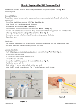
2. Feed Water Adaptor (1/2” or 3/8”): See Fig. 5. The Feed Water Adaptor comes with a
separate Needle Valve. The Adaptor goes inline onto your 1/2” or 3/8” cold water pipe. The
Needle Valve portion screws onto the Adaptor as shown in Fig. 5A.
Fig. 5
A. 1/2” x 3/8” Male-Female Water Supply Adapter
with O-ring.
B. 1/2” x 3/8” Male-Female Converter with O-ring.
C. 1/4” x 1/8” Male Needle Valve.
6
PA
P
RT
RT
II. IN
S
TALLIN
G
THE
S
Y
S
TE
M
Sp
ace
:
Make sure there is
su
su
ffff
ic
ic
ieie
nt
nt
s
pa
ce under the counter
f
or installat
io
o
n
n
(a(a
n
n
a
ar
ea o
f
about
17”L x 6”W x 1
8”
”
HH
H
ff
or
or
tt
h
he
h
system, 11
”D
x 1
8”
H
f
or tank).
The RO system is best installed under the kitchen sink. But i
f
that is not
f
easible you
c
an install the system anywhere where there is a cold water supply with su
ff
icient
water pressure
f
or the chosen RO model, and an outlet to drain o
ff
the waste wate
r
f
rom the system.
M
ounti
ng
g
:
:
NoNo
need to mount the RO system on
th
e e
e
wawa
ll
ll
. The RO system can stand in the sin
k
k
c
ca
binet
without mounting
g
, this mak
es
es
f
f
utut
ur
ur
e
e
f
ilter change easy and convenien
t.
I
I
I
f
f
f
y
ou pre
f
er to mount the system t
o
o
th
th
e
e
wa
wa
ll, please make sure it can be tak
en
n
d
d
owow
n
n
e
asily
f
or
f
ilter replacement.
Fe
Fe
ed
ed
Water:
R
O systems are designed
to
to
t
re
re
at both hard and so
f
t water and can
ha
ha
ndnd
le
le
incoming
TDS levels up to 200
0p
0p
pm
pm
.
.
Step 1: Feed Water Conne
ct
ct
ioio
nn
The RO s
ys
tem
mu
stst
st
bb
e e
co
co
nnected to the COLD water su
pp
ly
onl
y!
yppyy
1. Locate the
C
old water supply valve under the kitchen sink (the round or oblong handle on
the right side). Turn o
ff
the incoming cold water completely by turning the shut o
ff
handle
cl
oc
kw
is
e.
N
ote: I
f
the cold water shut o
ff
valve can
nono
n
t
t
t
tu
tu
r
rn
o
ff
the water, the main water s
up
p
pl
pl
y y
to the house must be shut o
ff
f
o
r
r
thth
e
e
in
in
stallation. Another o
pt
ion is to us
e
e
a
a
“s“s
el
f
piercing saddle valve”
f
rom
AP
AP
EC
EC
C
or
f
rom a local hardware store.
2
2.
Feed Water Ada
pt
or
(
1/2” or
3/
/
8”
8”
8
):
See F
i
g.
5.
T
he Feed Water Ada
pt
pt
oror
cc
om
om
o
es with a
s
eparate Needle Valve. The A
da
da
pt
pt
or
or
r
g
g
oes inline onto your 1/2” or 3/8”
coco
o
ld
ld
w
w
ater pipe. The
N
eedle Valve portion screw
s
s
onon
toto
t
t
h
he
Adaptor as shown in
F
ig. 5
A
.
Fig.
5
A
. 1/2” x 3/8” M
al
l
e-
e-
Fe
Fe
ma
m
le Water Supply Adapter
with O-ring.
B. 1/2” x 3/8” Male-Female Converter with O-rin
g.
g.
C.
1/4” x 1/8” Male Needle Valve
.

7
Fig. 5A - Needle Valve Installation.
Attach the needle valve (C) to water supply adapter (A). Please apply 5-6 wraps of
teflon tape to needle valve prior to connecting it to the water supply adapter (A).
Fig. 5B - If your pipe has a 1/2” Connection.
By attaching the 1/2” x 3/8” converter (B) to the Male end of the water supply adapter
(A), you now have a 1/2” Male and Female water supply adapter.
Fig. 5C - If your pipe has a 3/8” Connection.
By attaching the 1/2” x 3/8” converter (B) to the Female end of the water supply
adapter (A), you now have a 3/8” Male and Female water supply adapter.
Fig. 5A
Fig. 5B
Fig. 5C
1/2” Connection 3/8” Connection
7
Fi
F
g.
5
5
A
-
Needle Valve Installation.
Attach the needle valve
(C
(C
)
)
to
to
w
w
atat
er supply adapter (A). Please ap
pl
pl
y
y
5-5-
6 6
6
w
wr
aps o
f
te
f
lon tape to needle
va
a
lvlv
e
e
pr
pr
io
io
r
to
connecting it to the water supp
ly
y
aa
da
da
ptpt
e
er
(A).
F
i
g. 5
B
-
I
f
your pipe has a 1/2
”
”
”
Co
Co
nnection.
B
y attaching the 1/2” x 3/8” converter (B) to the Male end o
f
the water supply adapte
r
(
A), you now have a 1/2” Male and Female water supply adapter.
Fig. 5
C
-
I
f
your pipe has a 3/8” Connection.
B
y attaching the 1/2” x 3/8” converter (B) to
th
th
ee
FeFe
F
ma
m
le end o
f
the water supply
ad
d
apap
tete
r
r
r
(A), you now have a 3/8” Male an
d
d
d
FeFe
ma
m
le water supply adapter.
Fig
.
5A
Fi
g
5
A
F
i
g. 5
B
Fig. 5
C
Connectio
n
1/2”
o
nnectio
n
3
/8” C
o

8
Riser
Tube
For Flexible Line
Faucet
Shank
Main Water
Supply
Shut-off
Valve
Riser
Tube
For Solid Line
Faucet
Shank
Needle
Valve
Needle
Valve
Main Water
Supply
Shut-off
Valve
Sink
Sink
3. Recommend Connection For Flex Line Riser: See Fig.6A. & Fig. 6D. Loosen nut and
separate cold water riser tube from faucet shank. Gently bend riser tube so that the Feed
Water Adapter (Fig 5) fits onto the faucet shank. Connect the riser tube, the feed water
adapter, and faucet shank together and tighten.
For Solid Copper Riser: See Fig.6B. Follow the same procedure as for flex line. If the copper
riser cannot bend, then it’s best to replace it with a flex line riser. Then fit the feed water adaptor
the same way as described above.
Fig. 6A Fig. 6B
Option Connection Point: See Fig. 6E. The feed water adapter can also be installed between the
riser tube and faucet shank. Loosen nut and separate cold water riser tube from faucet shank.
Gently bend riser tube so that the Feed Water Adapter fits onto the faucet shank. Connect the
riser tube, feed water adapter, and faucet shank together and tighten.
8
Ri
i
i
i
se
s
s
s
r
r
r
r
Tu
Tu
Tu
Tu
be
e
e
e
Fo
r
Flexible Lin
e
Fa
uce
t
S
h
an
k
M
ai
n
Wa
te
r
S
u
pply
S
h
u
t-
off
Va
l
v
e
Riser
Tu
be
F
o
r
S
o
li
d
Line
F
a
u
ce
t
S
ha
n
k
Nee
dle
Va
l
v
e
Nee
dle
Va
l
v
e
M
ai
n
Wa
te
r
Su
pply
Sh
ut
-o
ff
V
a
l
v
e
Sin
k
S
in
k
3.
3
Re
Re
co
mm
e
n
d
Co
nn
ec
ti
o
n F
o
r Fl
e
x
Li
i
ne
ne
RR
i
se
r:
See
Fig.
6
A. & Fig.
6
D.
Lo
o
os
os
en
en
n
ut
ut
a
n
d
s
eparate cold water riser tube
f
ro
ro
m
m
f
a
uc
uc
et
shank. Gently bend riser tube
s
s
o
o
thth
atat
a
t
t
he
h
Feed
Water Adapter (Fig 5)
f
its ont
o
o
thth
e
e
fafa
uc
u
et shank. Connect the riser tube,
th
h
e e
fe
fe
eded
wate
r
adapter, and
f
aucet shank to
ge
ge
g
thth
er
er
a
a
nd tighte
n
.
For Solid Copper Riser:
Se
e
Fig.6B. Follow the same procedure as
f
or
f
lex line. I
f
the coppe
r
riser cannot bend, then it’s best to replace it with a
f
lex line riser. Then
f
it the
f
eed water adapto
r
the same way as described above.
Fig. 6A Fig. 6
B
O
pti
on
n
C
C
C
onon
o
ne
n
ction Point
:
See Fig.
6
E. The
fe
e
eded
w
w
at
at
er adapter can also be installed b
et
we
we
enen
t
t
he
h
ri
i
se
se
r
r
tutu
be and
f
aucet shank. Loosen nut
an
n
d
d
se
se
parate cold water riser tube
f
rom
f
a
uc
uc
etet
ss
haha
nk
.
GeGe
nt
ly bend riser tube so that the Feed
W
W
a
at
er Ada
pt
er
f
its onto the
f
aucet shank.
CC
C
on
on
nect the
i
ri
ser tube,
f
eed water adapter, and
fa
fa
uc
et
e
shank together and tighte
n
.

9
Fig. 6C
4. Needle Valve: See Fig. 6C. Screw the Needle Valve onto the Adaptor tightly. Apply 6-8 rounds
of Teflon tape onto Needle Valve before attaching it to the Adaptor.
To open needle valve: Turn needle handle counter-clockwise.
To close needle valve: Turn needle handle clockwise.
Test for leaks at this point: Close the Needle Valve (turn needle handle clockwise all the
way in to close) Turn ON the cold water supply to the sink faucet. If the Needle Valve or the
Adaptor leaks, check the connection and try applying more Teflon tape or tighten the brass
nut some more to stop the leak.
Fig. 6D Fig. 6E
9
Fi
Fi
g.
6
C
4
. Needle Valve
:
S
S
ee
ee
Fi
Fi
g.
6
C
. Screw the Needle Valve onto the Adaptor tightly. Apply 6-8 rounds
of T
eflon tape onto Needle Valve before attaching it to the Adaptor.
T
T
T
o
ope
n
needle valve
:
T
urn needle handle counter-clockwis
e.
TT
T
o
c
l
ose
needle valve:
T
urn needle handle clockwise.
TT
Test for leaks at this
p
oint:
p
Close t
he
he
N
N
ee
ee
e
d
dl
e Valve
(
turn needle handle
cloc
kw
w
is
is
e
e
al
al
l the
wa
y
in to clos
e)
Turn ON the co
ld
d
w
w
atat
er
er
s
up
pl
y
to the sink
f
aucet. I
f
the N
ee
e
dl
d
e
Va
Va
lve or the
Adaptor leaks, check the con
ne
e
ctct
ioio
nn
and try applying more Te
f
lon tape
or
t
t
igig
ht
ht
en
e
the brass
nut some more to sto
p
the
le
e
akak
.
.
Fi
g.
g.
6
D
FiFi
g
g.
6E

10
MOUNT DRAIN
SADDLE AT
EITHER
LOCATION
Step 2: Drain Saddle Installation
Note: To avoid annoying drainage noise, mount drain line as low as possible
on the vertical tailpiece, or on horizontal tailpiece.
There is constant water pressure “packed” inside the RO system which blocks the waste water
from backing-up into the system. So the waste water is “forced-drained”, not “gravity-drained”.
1. See Fig.7. The drain saddle assembly should be installed above the trap and on the vertical
or horizontal tailpiece . To reduce the drainage noise, mount the drain line as low as possible
above the trap, or on the horizontal tailpiece.
2. See Fig.8. Mark the position of the hole on the drain pipe and drill a 1/4’’ hole through one
side of the drain pipe . There is a piece of self-adhesive sponge provided. Glue this sponge
to the inside of the saddle, this will cushion any gap between the saddle and the pipe. Make
sure the hole on the sponge is thoroughly punched out, and is aligned to the hole on the
saddle.
Fig. 7
Fig. 8 Fig. 9
1
0
MO
UNT DRAI
N
S
ADDLE A
T
EITHER
LO
CA
TION
A
A
St
S
ep
p
2
: Drain Saddle Installatio
n
N
ote
:
To avoid annoy
in
n
gg
drdr
ai
ai
nage noise, mount drain line a
s
s
lolo
l
w w
as
a
possible
y
g
g
g, p
on the vertical
ta
a
a
ilil
pipi
ecec
e,
e
or on horizontal tailpiece.
p
p
,p
There is constant water pressure “packed” inside the RO system which blocks the waste wate
r
f
rom backing-up into the system. So the waste water is “
f
orced-drained”, not “gravity-drained”.
1.
See Fig.7. The drain saddle assembly should be in
st
t
alal
le
le
d
d
d
ab
ove the trap and on the vertical
o
r horiz
on
on
tata
l
l
ta
ta
a
ilpiece . To reduce the drainage n
oi
oi
i
sese
,
,
m
mo
unt the drain line as low as possibl
e
e
abov
e
e
th
th
t
ee
tr
tr
ap, or on the horizontal tailpiece.
2
.
See
F
i
g.8. Mark the position o
f
th
h
e
e
ho
ho
o
le on the drain pipe and drill a 1
/4
/4
’’
’’
h
h
olol
l
e
through one
s
ide o
f
the drain pipe . There
i
ss
a
a
pipi
ec
e o
f
sel
f
-adhesive sponge prov
id
eded
.
Gl
Gl
G
ue this sponge
to the inside o
f
the saddle,
t
t
t
hihi
h
ss
s
wi
wi
ll
ll
cushion any gap between the s
ad
d
dl
dl
e
e
an
a
d the pipe. Make
s
ure the hole on the s
po
ng
ng
e
e
is
is
thoroughly punched out, and
i
i
s
s
al
al
ig
ig
ne
e
d
d
d
to the hole on the
sadd
l
e
.
F
i
g.
7
7
F
i
g. 8
Fi
g.
9
Fi
9

11
Step 3: Drill A Hole For The RO Faucet
Drill 1/2” diameter hole for standard RO faucet. (Air-Gap faucet: drill 1&1/4” hole.)
For best results use a 1/2” carbide-tipped masonry drill bit.
Wear safety glasses to protect your eyes while drilling the faucet hole.
Note: No need to drill a hole if an existing hole is available:
a) Spare hole: If there is a spare hole in the sink covered by a chrome cover, simply remove the chrome
cover and install the RO faucet there.
b) Spray hose: If the spray hose is not in use, remove the hose, and mount the RO faucet there. Remember
to plug up the outlet under the main faucet. If the spray hose uses a diverter at the base of the spout, be sure
to remove it to avoid trouble later on.
c) Hanging faucet: If drilling a hole is not feasible (i.e. rental home, drill tool not available etc.), the faucet
can just hang on the cabinet door or wherever that is convenient. Be creative!
When drilling a hole for the RO faucet, choose a location that looks good, works well, and is most con-
venient for dispensing pure water. An ample flat area is required for the faucet base so that the faucet
can be drawn down tightly.
1. Faucet location: Make sure the faucet stud will be accessible from below when the hole is drilled.
If space is not available on the upper sink area, the faucet can be located on the counter top by the
edge of the sink. If the counter top is ceramic tile, the method for drilling the hole will be the same as
for porcelain sinks.
2. For Stainless Steel Sink: Before using a 1/2” carbide drill bit, an indent should be made with a
center punch to keep the drill bit from walking. A small pilot hole will also aid the drill bit.
3. See Fig.9, 9A. Make sure to align the drain saddle hole to the drilled hole perfectly.
Mis-aligning these two holes will block the drain water and cause membrane damage. Attach the
drain saddle to the drain pipe and tighten the two screws evenly.
4. Once the drain saddle is secured, push 1/4” black drain tubing into the Quick Connect fitting on the
saddle. DO NOT use a “Insert” on the drain tubing.
Fig. 9A
11
St
ep
ep
3
3
: Drill A Hole For The RO Fa
uc
c
et
et
Drill 1/2” diameter hole
f
or
or
s
s
ta
ta
nd
nd
ard RO
f
aucet.
(
Air-Gap
f
aucet: d
ri
i
ll
ll
11
&1
&1
/4/4
” hole.
)
For best results use a 1
/2
/2
”
c
ca
rbide-tipped masonry drill bit.
Wear sa
f
ety gl
as
as
s
sese
s s
s
to
to
protect your eyes while drilling the
f
aucet hole.
N
ote
:
No need to drill a hole if an existing hole is available:
g
a)
Sp
are hole: I
f
there is a
sp
are hole in the sink cov
er
er
r
eded
bb
y
y
a chrome cover, si
mp
ly
remove the
ch
h
ro
ro
me
me
c
over and install the RO
f
aucet there.
b
b
)
)
Sp
Sp
p
ra
r
y hose: I
f
the spray hose is not in use
,
,
re
e
mo
mo
ve the hose, and mount the RO
f
aucet
t
t
hehe
re
re
.
R
Re
membe
r
to
o
pp
p
lu
lu
g up the outlet under the main
f
aucet.
I
I
f
f
thth
e
e
sp
sp
ray hose uses a diverter at the base
o
o
f
f
t
th
e spout, be sure
toto
r
emove it to avoid trouble later on.
c
)
Hanging
f
aucet:
If
drilling a
ho
le
le
i
i
s
s
no
n
t
f
easible (i.e. rental home, drill tool
nn
otot
a
a
va
il
able etc.), the
f
aucet
c
an just hang on the cabinet d
oo
o
r
r
r
oror
r
w
w
he
he
rever that is convenient. Be creative
!
When drilling a hole
f
or
r
tt
hehe
RR
O
O
f
aucet, choose a location that loo
ks
ks
gg
oooo
d,
d,
works well, and is most con
-
venient
f
or dispensing
p
p
urur
e
e
wawa
wa
te
t
r. An ample
f
lat area is required
f
or the
f
aucet base so that the
f
auc
et
c
an be drawn down tightly.
1
. Fa
uce
t l
oc
ati
o
n:
M
ake sure the
f
aucet stud will be accessible
f
rom below when the hole
is
is
dd
ri
ri
i
ll
ll
ed
ed
.
If
space is not available on the upper sink
ar
ea
ea
, the
f
aucet can be located on the coun
te
te
r
r
to
to
p
p
by the
ed
ed
ge
g
o
f
the sink. I
f
the counter top is cera
mi
mi
c
c
titi
le
le
, the method
f
or drilling the hole wil
l
l
bebe
t
t
h
he
same as
fofo
r
r
po
p
rcelain sinks.
2
2.
Fo
r
S
tainl
ess
S
t
ee
l
S
ink
:
Be
f
ore
us
us
in
in
g
g
a
a
1/2” carbide drill bit, an indent sh
ou
ou
ldld
b
b
e
e
made with a
c
enter punch to keep the drill b
it
it
f
f
roro
o
m
m
walking. A small pilot hole will als
o
o
aiai
d
d
d
th
th
e drill bit.
3
. Se
e
e
Fi
Fi
g.
g.
9,
9
9
A
.
Make sure to align the d
ra
a
inin
ss
adad
d
dl
e hole to the drilled hole p
er
r
fe
fe
ct
ct
ly
ly
gp
y
y
.
y
y
MM
is
is
-a
-a
li
l
gning these two holes will block t
he
d
ra
ra
in
in
water and cause membrane da
ma
ge
.
AtAt
tach th
e
d
rara
a
in saddle to the drain pipe and ti
gh
g
ten
th
th
h
e
e
t
tw
o screws evenl
y.
4
4.
Once the drain saddle is secured
,
,
pupu
sh
sh
1
1
/4
” black drain tubing into the Quic
k
k
Co
Co
n
nn
ect
f
itting on the
sadd
l
e
.
D
O
N
OT use a “Insert”
on
n
t
t
he
he
d
d
rain tubing.
Fig. 9
A

12
Black Locating Washer
Lock Washer
Lock Nut
Faucet Adapter
Tubing
Counter Top
Counter Top
Opening
Please hand tighten only!
Faucet Base
Step 4: Mounting The Faucet
1. Mount the faucet as shown in Fig.10.
Fig. 10
2.
Attach threaded end of faucet adapter to the
faucet metal stem. No teflon tape needed here.
3. Connect the Clear line to the faucet.
4. The faucet has a solid metal handle
that controls the flow of purified water
exiting the faucet. Turn the handle to
horizontal position to release the water
and vertically to shut off.
3. For Porcelain Sink: Porcelain enameled sinks can readily be chipped if care is not exercised
when drilling the hole. Before starting the drill motor, apply firm downward pressure on the bit
until a crunching occurs. This will help keep the drill bit from walking when starting the hole.
A small pilot hole will also aid the drill bit.
Note: Immediately after the hole drilling is done, clean up all metal chips, as metal chips
will stain the porcelain!!
Step 5: Positioning The System
1. Main System: The main system can stand in the sink cabinet. No need
to mount the system to the wall. If you prefer to mount the system to the
wall, please make sure it can be taken down easily for filter replacement.
2. Tank: The storage tank can also lay on its side if needed. The tank works fine in this
position. If the tank cannot fit under the kitchen sink, it can be placed elsewhere up to 20 feet
away from the RO system without much pressure loss.
1
2
B
l
a
ck
L
ocatin
g W
W
ash
ash
er
er
Loc
c
k
k
Wa
Wa
W
she
she
r
r
Lo
c
k
Nut
LkNt
Fa
u
cet A
d
a
p
t
e
r
T
u
b
in
g
Cou
nte
nte
r
r
ToTo
p
p
C
ounter Top
Ope
nin
g
P
lease hand tighten o
nly
!
F
auc
c
et B
a
se
Step 4: Mounting The Fauce
t
1. Mount t
he
e
f
f
f
au
a
cet as shown in
Fi
g.10.
Fig. 1
0
2.
At
ta
ta
ch
ch
t
t
hr
hr
h
e
ea
ded end o
f
f
aucet adapter to the
fa
fa
uc
uc
et
et
m
m
etal stem. No te
f
lon tape needed h
er
r
e.e.
3.
3.
Connect the
C
l
ea
r
l
ine to the
f
auc
et
et
.
4.
The
f
aucet has a solid metal
h
h
anan
dl
dl
e
e
that controls the
f
low o
f
pu
u
ri
ri
fi
fi
ed
ed
wate
r
e
xiting the
f
aucet.
Tu
Tu
rn
rn
r
t
t
he
h
h
andle to
horizontal positio
n
n
n
toto
r
r
elel
e
ea
se the wate
r
and vertically to
sh
h
utut
oo
ffff
..
3.
F
F
or
or
P
P
o
r
ce
lain
S
ink
:
Porcelain enameled
si
si
nknk
s
s
ca
ca
n readily be chipped i
f
care is
no
t
t
exex
er
er
ci
sed
wh
wh
en drilling the hole. Be
f
ore starting
th
th
e
e
drdr
il
l motor, apply
f
irm downward
p
p
re
ss
ur
e
e
o
on
the bit
until a crunching occurs. This will he
lp
k
k
k
e
ee
e
p
the drill bit
f
rom walking whe
n
n
stst
arar
titi
ng
n
t
t
he hole.
A small pilot hole will also a
id
d
tt
hehe
dd
ri
ri
r
ll
b
b
it
.
N
ote
:
Immediately a
f
ter the
ho
o
o
le
le
d
d
ri
r
lling is done, clean up all metal chips, as metal chips
will stain the porcelain!!
Step 5: Positioning The Syste
m
1.
M
ain System
:
The main system can stand in the sink cabinet. No need
to mount the system to the wall. I
f
you
pr
ef
e
er to mount the system to the
wall, please make sure it can be taken
dd
ow
ow
n
n
easily
f
or
f
ilter replacement.
2.
2.
2
Ta
nk: The storage tank can als
o
o
la
la
y
y
on
on
its side i
f
needed. The tank works
fi
fi
ne
ne
in
h
th
is
position. I
f
the tank cannot
f
it
uu
ndnd
er
er
t
t
he kitchen sink, it can be placed el
se
se
wh
wh
erer
e
e
up to 20
f
eet
away
f
rom the RO system
wi
wi
w
th
th
ou
ou
o
t much pressure loss.

13
Step 6: Connecting The System
Summary of Tubing Connections:
There are 4 connections: See Fig. 11 and 11A
Point A to X: Connect RO to COLD water supply — Red tubing.
Point G to Y: Connect product water from 5
th
-stage filter to tank — Yellow tubing. This tubing
is a 2-way line, Product water enters and leaves the tank via this line.
Point H to Z: Connect product water from 5
th
-stage output to RO faucet — Clear tubing.
Drain line to W: Connect waste water from 4
th
-stage membrane to drain outlet — Black tubing.
Please Note: The diagram below is for our Non Pump RO-90 and RO-PH90. If you are install
ing the RO-Pump, please refer to the diagram in the addendum.
Fig. 11
1
3
St
S
ep
6
6
: Connecting The Syste
m
Su
mmary o
f
Tubing Connecti
on
on
s:s:
T
h
e
r
e
a
r
e
4
co
nn
ec
ti
o
n
s:
See Fig. 11 and 11A
Po
int
A
to
A
X
:
Connect RO to COLD water supply
—
Re
Re
d
tubing.
Po
int
G
t
o
Y
:
:
Connect product water
f
rom 5
th
-
s
ta
a
gege
g
f
f
il
il
te
te
r to tank
—
Yellow
tubing. This tub
in
in
gg
w
i
s a 2-way line, Product water e
nt
nt
er
er
s
an
an
d
leaves the tank via this line.
Po
in
n
t
t
H
H
t
t
o o
Z
:
Connect product water
f
r
om
m
5
5
5
th
th
-
-s
tage output to RO
f
aucet
—
Clear
t
t
t
ub
ub
inin
g.
g.
r
Dr
Dr
a
ai
n lin
e
t
o
W
:
Connect waste water
fr
fr
om
m
4
th
-
stage membrane to drain outlet
—
Bl
Bl
ac
ac
k
k
tubing.
k
Please Not
e:
The diagr
am
m
b
b
elel
ow
o
is
f
or our Non Pump RO-90 and R
O-
O
PH
PH
90
90
. I
f
you are install
ing t
he
he
e
R
R
O-
Pu
Pu
mp, please re
f
er to the diagram in the addendum.
Fi
g.
1
1

14
Fig. 11A
Details on Tubing Connections:
To ensure a smooth and correct installation, please connect the water lines following the se-
quence and order outlined below. Refer to Fig.11 & 11A for proper point locations.
1. Point Z Faucet connection:
Tubing color: Clear tubing. Connect the CLEAR tubing to the base of the RO faucet.
Fitting type: Quick Connect Fitting. Simply push Clear tubing into Quick Connect fitting. No Insert,
Sleeve or Nut needed here. (Attach threaded end of faucet adapter to the faucet metal
stem. No teflon tape needed here)
2. Point X Feed water connection:
Tubing color: Red tubing. Connect the RED tubing to the Feed Water Needle Valve.
Fitting type: Metal compression nut fitting.
See Fig.1B on page 4. Use plastic sleeve.
Add “insert” to tubing. No teflon tape here. Tighten nut with wrench.
Tips!
If Point X leaks after you have tightened the brass nut, check to make sure you did put the
plastic “insert and sleeve” onto the tubing. If the insert is already in place, then try
applying Teflon tape from the threaded metal stud all the way to the plastic tubing, wrap
the whole connection with 8-10 rounds of Teflon tape. Smooth out the tape on the
threaded part with your fingers. Tighten brass nut again. This should stop the leak.
If the plastic sleeve is damaged, you can use the metal sleeve, but you need to apply
Teflon tape as described above, this should stop the leak.
1
4
Fig. 11
A
Details on Tubing
Co
Co
nnnn
n
ec
ec
tions:
To ensure a smooth and correct installation, please connect the water lines
f
ollowing the s
e
-
quence and order
outlined below. Refer to
r
Fig.11
&
&
&
&
1
1
1A
1A
for proper point locations.
A
1.
P
P
oi
o
nt
Z
Fa
uc
et
c
on
ne
ct
io
n:
TuTu
bibi
b
n
ng
color: Clear tubi
ng
. Connect the
CL
L
EA
EA
R
R
tu
t
bi
ng
to the base o
f
the RO
f
aucet.
Fi
Fi
t
tt
ing type:
Q
uick Connect
F
i
tting.
Si
mp
mp
m
ly
y
push Clear tubing into Quick Connect
fi
fi
tt
tt
inin
g.g.
g
N
N
o Insert,
Sleeve or Nut needed
h
h
er
er
e.e.
.
(
(
At
A
tach threaded end o
f
f
aucet adap
te
e
r
r
toto
t
t
he
he
f
f
aucet metal
s
tem. No te
f
lon ta
pe
pe
nn
eeee
de
de
d here
)
2
.
P
o
int X Feed water
c
c
on
on
ne
ction
:
Tubing color
:
R
ed t
ub
ub
in
in
g.
g.
C
C
o
on
nect the RED tubing to the Feed Water
Ne
Ne
ed
ed
le Valve.
F
itting type:
M
etal
co
co
mp
mp
r
re
ssion nut
f
itting.
See
Fig.1B
on
page
4
.
Use
plastic sleeve.
Ad
d
“i
ns
er
t”
to tubing. No te
f
lon tape here. Tighten nut with wrench.
T
i
ps!
If
Point X leak
s
a
f
ter you have tightened the brass nut, check to make sure you did
pupu
t t
thth
e
e
pl
astic “insert and sleeve” onto the tubi
ng
. I
f
the insert is alrea
dy
in
pl
ace, then
tr
tr
y
y
applying
T
eflon tape from the th
re
re
ad
ad
a
ed metal stud all the way to the plastic tub
in
in
g,
g,
w
w
ra
ra
p
T
T
the whole connection with 8-
10
0
r
r
ouou
nd
n
s o
f
Te
f
lon tape. Smooth out the tape
on
on
t
t
hehe
threaded part with your
f
i
ng
ng
er
er
s.s.
TT
T
ig
ig
hten brass nut again. This should st
op
p
t
t
he
he
l
l
e
ea
k
k.
If
the plastic sleeve
is
dd
am
am
ag
ag
ed, you can use the metal sleeve, but
yo
yo
u
u
nene
ed
ed
to apply
Te
f
lon tape as des
cr
cr
c
ibib
eded
e
above, this should stop the leak.

15
3. Point W Waste water connection:
Tubing color: Black tubing. Connect the BLACK tubing from the RO to the Drain Saddle.
Fitting type: Quick-Connect fitting on drain saddle. No teflon tape.
Do Not add ”insert” into Black tubing. Simply push tubing into port.
4. Point A System water inlet (to Stage 1 prefilter) connection:
Tubing color: Red tubing. Connect the RED tubing from the Feed Water Valve to the RO’s stage -1
pre-filter.
Fitting type: Quick Connect fitting
See Fig.1 on page 4. Simply push the Red tubing into the Quick
Connect fitting. No Inserts, Sleeves or Nuts are needed to secure the connection. No
teflon tape is needed here.
5. Point H Stage-5 filtered water to faucet connection:
Tubing color: Clear tubing. Connect the CLEAR tubing from the faucet base stud to the Stage-5 filter’s
outflow end at point H. (See “Flow -->” arrow on the filter for flow direction.)
Fitting type: Quick Connect fitting
See Fig.1 on page 4. Simply push the Clear tubing into outlet
on the 5th stage filter. No Inserts, Sleeves or Nuts are needed to secure the
connection. No Teflon tape is needed here.
Please Note: There are two end plugs on the stage-5 filter that has to be removed before
inserting the tubing. Please refer to Fig. 1A on page 4 for removal instruction.
6. Point G Stage-5 filter’s T-fitting connection:
Tubing color: Yellow tubing. Connect the YELLOW tubing to Stage-5 filter’s T-fitting.
Fitting type: Quick Connect fitting
See Fig.1. Simply push the Yellow tubing into the 5th stage filter’s
T Fitting. No Inserts, Sleeves or Nuts are needed to secure the connection. No Teflon tape
needed here.
(Note: If the unit comes with a UV Light, connect the Yellow tubing to the T- fitting on the
UV, as the Stage 5 filter will not have a T-fitting).
15
3.
3
P
P
o
oi
nt
W
W
aste water connection:
W
W
T
Tu
bing color
:
B
lack tubing. Conn
ec
c
t t
thth
e e
BL
BL
AC
AC
K tubing
f
r
om
th
e
R
O
t
o
th
e
Dr
a
in
S
ad
ad
dldl
d
e.e.
F
itting type:
Q
uic
k
-
Connect
f
itti
ng
g
g
oo
nn
drdr
ai
ai
a
n saddle. No te
f
lon tape.
Do
N
ot add ”inser
t”
”
i
i
i
nt
nt
o
o
B
Bl
ack tubing. Simply push tubing into port.
4.
P
oi
nt
A
System water inlet (to Stage 1 pre
f
ilter) connection
:
Tubi
ng
color
:
R
ed tubin
g.
Connect the RED tubin
g
f
r
om
the
F
F
eeee
d
d
d
Water Valve to the RO’s st
ag
e -1
pr
pr
p
e-
e
f
ilter.
F
itting type:
QuQu
ic
ic
i
k Connect
f
itting
S
ee Fig.1
on
pa
gege
e
44
.
.
S
S
imply push the Red tubing into the Q
ui
i
ckck
c
C
Co
nnect
f
itting. No Inserts, Sleeves o
r
NuNu
tsts
are needed to secure the connection. No
te
f
lon tape is needed here
.
5.
5.
P
oi
nt H Stag
e
-
5
f
iltered water
to
to
f
au
au
cet connection
:
Tubing color
:
Clear tubing. Conn
ec
ec
t
t
thth
e
e
CL
C
EAR tubing
f
r
om
the
f
aucet base stu
d
d
toto
t
t
t
he
he
S
S
tage-5
f
ilter’s
outflow
end at
w
po
o
in
in
t t
H.
H.
(
See
“
Flow --
>
”
arrow on the
f
ilter
f
or
f
l
ow
w
dd
irir
ec
ec
t
ti
on.)
F
itting type: Quick Co
nn
n
ec
ec
t
f
i
tt
tt
in
in
g
S
Se
e Fig.1
on
page
4
. Simply push the Clear tubing into outlet
on the
5t
5t
t
hh
h
st
st
agag
e
e
fi
lt
lt
er. No Inserts, Sleeves or Nuts are needed to secure the
conne
ct
ioio
n.n.
N
N
N
o
o
T
Te
f
lon tape is needed here.
Please Note:
There are two end plugs on the stage-5
f
il
ter that has to be removed before
inserting the tubing
. Please refer to
F
F
F
ig
ig
ig
i
.
1A
1A
on page 4 for removal instruction.
6.
P
oi
nt
G
Stag
e
-
5
f
ilter’s T-
f
itting conn
ec
ec
ti
ti
on
on
:
Tu
Tu
bi
bi
ng
n
color
:
Y
ellow tubi
ng
. Connect the
YE
E
LL
L
OWOW
tubin
g
to Sta
ge
-5 filter’s T-fittin
g.
Y
Y
FiFi
tt
tt
i
in
g type: Quick Connect
f
itting
S
e
e
e
e
Fi
F
g.
1
1.
Simply push the Yellow tubing into
th
th
e
5t5t
h
h
s
st
age
f
ilter’s
T Fitting. No Inserts, Sl
ee
ee
ve
ve
s
or
o
Nuts are needed to secure the con
ne
ne
ctct
t
ioio
n.n.
No Te
f
lon tape
n
eeded
h
e
r
e
.
(
N
ote: I
f
the
un
n
it
it
c
c
om
om
es with a UV Ligh
t
, connect the
Ye
Ye
ll
ll
ow
ow
t
ub
ub
b
i
in
g to the T-
f
itting on the
U
U
V,
V,
a
a
s
th
h
e
e
Stage 5
f
ilter will not have a T-
f
itti
ng
g
).).

16
Ball Valve
(Recommended)
Tee tting for icemaker & output
Ball Valve Position
ON OFF
Z
H
Y
X
Optional Connection
Insert
Sleeve
Tube
Metal Nut
7. Point Y Tank’s input & output connection:
Prepare tank: See Fig.12. Apply 6-8 wraps of Teflon tape to tank’s threaded Output stem on top of
tank (remove rubber cap if there is one). Screw tank Valve onto Output stem.
Tubing color: Yellow tubing. Connect the YELLOW tubing from Stage-5 T-fitting to the tank’s valve.
Fitting type: Quick-Connect fitting on ball valve. Simply push Yellow tubing into valve port.
Air pressure: The 4 gallon tank comes pre charged at 5 psi, 14 gallon tank at 7 psi.
Fig. 12
OFF Position ON Position
Tank Ball Valve
Option: Ice-maker Connection
If you want to connect product water from the RO to your ice-maker, you will need:
x One T-fitting, preferably the quick-connect type fitting
x Extra ¼ “ tubing long enough to go from the RO system to your ice-maker
x One shut-off valve, preferably the quick-connect type.
See Fig.13. Before connecting the product water line from Point Z to H, add a T-fitting near
point H to divert product water to both the ice-maker and the faucet. It is best open the line to
the ice maker after the first tank has been discarded and the 2nd tank has completely filled.
Standard 4-gallon Tank Diagram:
Refrigerator
Fig. 13
1
6
Ball
V
al
ve
(
Recommen
d
e
d)
Tee ttin
g
for icemaker & outpu
t
B
a
ll V
a
lve P
o
si
tion
O
NOF
F
Z
H
Y
X
Optiona
l
Connectio
n
I
n
se
r
t
Sleeve
Tube
M
et
al
N
ut
7.
7
P
P
o
oi
nt Y
T
ank’s input & output c
on
n
ne
ne
ctct
ion:
TT
P
Pr
epare tank
:
See
F
i
g.12.
Apply
6-
6-
8 8
wrwr
ap
ap
s
of
Te
f
lon tape to tank’s threaded
Ou
tp
p
utut
p
s
s
te
te
m
m
on top o
f
tank (remove rubbe
r
ca
c
ca
pp
if
if
t
t
h
he
h
re is one). Screw tank Valve onto Outpu
t
t
st
st
e
em
.
Tubing color
:
Y
ellow tubing. Connect the YELLOW tubing
Y
Y
f
r
o
m Stage-5 T-
f
itting to the tank’s valve.
F
itting type:
Q
uic
k
-
Connect
f
itting on ball valve. Simply push Yellow tubing into valve port.
A
ir pressure
:
The 4 gallon tank comes pre charged at 5 ps
i,
i,
1
1
4
4
gallon tank at 7 psi.
F
i
g. 12
O
FF
Po
o
si
si
ti
ti
on
ON
Positio
n
T
ank Ball
Va
lv
e
Option:
p
I
ce
-m
a
k
e
r
Co
nn
ec
ti
on
If
y
y
ou
ou
want to connect product water
f
rom th
e
e
e
RORO
R
t
t
o
o
your ice-maker, you will need
:
x
One T-
f
itting, pre
f
erably the qu
ic
k-
k-
co
co
nn
nn
ect type
f
itting
x
Extra ¼ “ tubing long enough
t
t
o
o
go
go
o
f
rom the RO system to your ice-
ma
a
keke
r
r
x
One shut-o
ff
valve, pre
f
er
ab
b
ly
ly
t
t
he
he
quick-connect type.
See
F
i
g.13. Be
f
ore connect
in
in
g
g
thth
e
e
product water line
f
rom Point
Z
Z
to
to
H,
ad
ad
a
d a T-
f
itting nea
r
point H to divert prod
uc
uc
t
t
wa
tete
r
r
to both the ice-maker and the
fa
a
ucuc
et
et
e
.
ItIt
is best open the line to
the ice make
r
after
tt
hehe
f
f
irir
st
st
tank has been discarded and the 2
nd
nd
tt
anan
k k
ha
s completely filled.
r
Standard 4-gallon
Ta
Ta
nk
nk
DD
ia
ia
gram:
R
e
f
rigerator
Fi
Fi
g.
g.
1
1
3

17
Using RO for Ice-maker only:
If you want the RO to feed your ice-maker (fridge) only, you should still connect the RO faucet
as a 2nd outlet. This allows you to drain the tank, flush new filters through the faucet rather than
through your icemaker line. You can hang the faucet by the system and not mount it.
Option: Multiple Outputs - Add Shut Off Valve:
If your RO is feeding several output points (icemaker, fridge, bathroom), you should add a
Shut-Off valve to each output line (except the RO spigot line). This way, if you ever need to
diagnose a problem in the system, you can easily shut off these lines to isolate the water flow for
accurate troubleshooting.
Step 7: System Start-Up
1. Turn on feed water: Slowly, turn on your Cold water supply. Turn on the Needle Valve (turn
counter-clockwise) to allow the raw water to enter the system. Check for leaks!
2. Turn on tank valve: Turn on the tank’s ball valve to allow water to enter the tank. The
tank’s valve is “ON” when the valve handle is parallel (in the same direction) with the valve’s
outlet (see Fig.12). Check for leaks!
3. Wait for tank to fill: Before usage, allow the tank to fill. Tank normally takes 2-3 hours to
fill. When the tank is filled, the RO will shut off automatically.
4. Drain Tank: Please do not use the first tank of water. Once the tank has filled, open
the drinking water faucet to drain the tank and filters. It will usually take about 5 min-
utes to flush the unit. When the tank is completely empty water will simply Trickle out the
faucet. At this time, please close the drinking faucet and allow the unit another 2-3 hours to
refill the tank. The 2nd tank of water will be ready for use.
Please Note: Water may come out dark for the first few seconds on the initial flush, and then
clear right up. This is due to the GAC (granular activated carbon) post filter.
5. Clean up area: Allow the system to run while cleaning up tools and work area.
6. Check for leaks! Make sure no leaking at joints, fittings, valves, and tubing connections.
Congratulations! You have successfully installed the Reverse Osmosis System!
Note:
If your RO makes an annoying noise. See Troubleshoot Guide section for explanation and
instructions on page 29.
* * * End Installation Section * * *
17
Us
U
in
i
g
g
RO
f
or Ice-maker only:
If
you want the RO to
f
eed your
ic
c
e-e-
mama
ke
ke
k
r
(
(f
ridge) only, you should still con
ne
ne
ctct
tt
he
he
RO
f
aucet
as
a
2n
d
ou
tl
e
t. This allows you
t
t
oo
dr
dr
ai
ai
n
n
the tank,
f
lush new
f
ilters through the
f
fa
ucet rather than
through your icemaker line. You can
ha
ha
ng the
f
aucet by the system and not mount it.
Option:
p
Multiple Outputs - Add Shut Off V
al
ve
:
VV
If
your RO is
f
eeding several output points (icemaker,
f
ridg
e,
e,
bathroom), you should add a
Shut-O
ff
valve to each output line (except the RO spi
go
o
t
t
li
li
nene
n
).
)
This way, i
f
you ever need to
d
iagnose a
p
p
roro
blbl
em
e
e
in the system, you can easily shu
t
t
of
of
f
f
th
th
ese lines to isolate the water
f
low
f
o
r
accurate
t
t
roro
o
ub
ub
le
le
sh
ooting
.
St
t
ep
ep
7
7
: System Start-U
p
1.
1
T
ur
n
on
f
ee
d
wa
te
r:
TT
Slowly, tu
rn
rn
oo
n
n
y
yo
ur Cold water supply. Turn on
th
h
e e
NeNe
ed
ed
le
e
Valve (turn
co
un
te
r-
cl
oc
kw
is
e
)
to allow
t
t
hehe
r
r
aw
aw
water to enter the system.
Ch
ec
k
fo
fo
r
r
lele
ak
ak
s!
2.
T
urn on tank valve
:
:
Tu
Tu
rn
o
o
n
n
the tank’s ball valve to allow water to enter the tank. The
tank’s valve i
s
“
ON
N
N
””
whwh
en
e
the valve handle is parallel (in the same direction) with the valve’s
o
utlet
(
s
ee F
i
g.1
2
).).
Ch
Ch
Ch
ec
ec
k
k
fo
r l
ea
k
s!
3
. Wait
f
or tank to
f
ill:
B
e
f
ore usage, allow the tank to
f
ill. Tank normally takes
2
-
3
h
ou
r
s
t
o
f
ill. When the tank is
f
illed, the RO will shut o
ff
au
to
o
mama
ti
t
cally.
4
. Dr
a
in T
a
nk:
Please do not use the first ta
nk
nk
oo
f f
wa
w
ter. Once the tank has fille
d,
o
o
pepe
nn
,
p
p
the drinking water faucet to drain the t
an
an
k
k
an
a
d
d
filters.
g
It will usually take abou
t
t
5 5
mimi
n
-
utut
t
es
e
t
o
f
l
us
h th
e
u
nit. When the tank is c
om
m
plpl
p
e
et
el
y empty water will simply Trickle
ou
ou
t t
thth
e
e
fa
fa
ucet. At this time, please close the
d
d
ri
ri
nknk
in
in
g
g
f
aucet and allow the unit anot
he
e
r
r
2-
2
3
ho
h
urs to
re
f
ill the tank. The 2nd tank o
f
w
at
t
er
er
e
w
il
l
l
l
b
be
ready
f
or use.
Pl
ea
se
N
ot
e:
Water may c
om
om
ee
ou
ou
t
t
dark
f
or the
f
irst
f
ew seconds on th
e
e
inin
i
it
ial
f
lush, and then
c
lear right up. This is due
to
o
t
t
he
he
h
GAC (granular activated carbon) p
os
os
t
t
fi
fi
lt
lt
er.
5
.
C
lean up area:
Al
Al
lo
lo
l
w
w
w
th
h
e system to run while cleaning up
to
to
olol
s s
an
an
d work are
a.
6
.
C
h
ec
k
fo
r l
ea
k
s!
s!
MaMa
a
ke
k
k
sure no leaking
at joints,
f
ittings, valves, and tubing connections.
C
ongratulations! You have success
f
ully installed the Reverse Osmosis System
!
N
ote
:
I
f
your RO makes an annoyi
ng
ng
nn
oioi
o
se
se
. See Troubleshoot Guide section
f
or e
xp
p
lala
nana
ti
ti
on and
i
nstruct
i
ons on page 29.
*
*
*
*
*
*
End Installation Section * *
*
/