Part No: 7021-7534 Rev: A
Page: 1 of 3
E.C.O. No: 295-014
CUSTOMER SERVICE PHONE: 1-800-426-8562
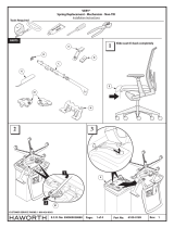
1. If necessary, remove damaged or partial
components from the arm of the TAS chair.
2. Insert lock liner into arm cap support
weldment (note orientation of liner in Fig. 1).
Buttons on liner must snap into holes in
weldment.
3. Insert lock rod through spring and into arm
cap support weldment, extending rod
through weldment (Fig. 1).
4. Insert locking gear and pin as shown in
Fig. 2. NOTE: Lock rod must be pulled up
to insert gear. The activation lever maybe
snapped onto the top of the lock rod to
assist in pulling the rod out of the way.
5. Snap stop collar into cover tube, making
sure tabs engage in slots (Fig. 3A, 3B).
ARM CAP
SUPPORT
WELDMENT
LOCK
LINER
SPRING
LOCK
ROD
BUTTON
LOCKING
GEAR
PIN
ACTIVATION
LEVER
FIG. 1
FIG. 2
FIG. 3A FIG. 3B
TAS™ ADJUSTABLE ARM REPLACEMENT
Installation Instructions
COVER
TUBE
STOP
COLLAR

Part No: 7021-7534 Rev: A
Page: 2 of 3
E.C.O. No: 295-014
CUSTOMER SERVICE PHONE: 1-800-426-8562
FIG. 4A FIG. 4B
6. Snap together the two halves of the
adjustable arm liner (Fig. 4A, 4B).
7. Place cover tube on arm of TAS chair
(Fig. 5).
8. Insert assembled adjustable arm liner into
the arm of the chair. Orient the liner such
that the lock button aligns with the hole in
the chair arm (Figs. 6, 7).
COVER
TUBE
ARM OF
CHAIR
ADJUSTABLE
ARM LINER
FIG. 5 FIG. 6 FIG. 7

Part No: 7021-7534 Rev: A
Page: 3 of 3
E.C.O. No: 295-014
CUSTOMER SERVICE PHONE: 1-800-426-8562
9. Place aesthetic collar over cover tube. Do
not screw them together yet (Fig. 8).
10. Insert arm cap support weldment assembly
into adjustable arm liner (Fig. 9). The locking
gear must be disengaged by pulling up on
lock rod, as in step 4.
11. Secure arm cap assembly to cover tube with
aesthetic collar. Attach with two (2) #6-32 x
7/8" screws, using a T-15 TORX bit (Fig. 10).
12. Install the activation button and front and rear
cradles as shown in Fig. 10. It may be
necessary to temporarily disconnect
activation lever from lock rod.
NOTE: The internal arm-rest components
may be held in place with masking tape until
they are secured with the arm cap.
FIG. 8
AESTHETIC
COLLAR
COVER
TUBE
FIG. 9
FIG. 10
#6-32 x 7/8"
SCREW (2)
DISENGAGE LOCKING
GEAR BY PULLING UP
ON LOCK ROD
REAR
CRADLE
ACTIVATION
LEVER ACTIVATION
BUTTON
FRONT
CRADLE
/


