Page is loading ...

THANK YOU
We appreciate the trust and condence you have placed in Veranda through the purchase of this railing. We strive to continually create quality
products designed to enhance your home. Visit us online to see our full line of products available for your home improvement needs. Thank you
for choosing Veranda!
INSTALLATION MANUAL
VERANDA REGENCY RAILING WITH METAL BALUSTERS
Questions, problems, missing parts? Before returning to the store,
call Veranda Customer Service
8 a.m. - 7 p.m., EST, Monday - Friday, 9 a.m. - 6 p.m., EST, Saturday
1-800-230-7547
HOMEDEPOT.COM/VERANDA
Model # SEC17 RW U8 W/MTL KD
SEC17 RWS U8 W/MT KD

2
Table of Contents
Table of Contents ...................................2
Safety Information ..................................2
Warranty ..........................................3
Pre-Installation .....................................4
Line Rail Installation .................................7
Stair Railing Installation ..............................9
Special Notes On Stair Railing ........................9
Safety Information
Read and understand this entire manual before you begin the
installation of your railing.
WARNING: Use extreme caution when using power tools.
IMPORTANT: Please consult local zoning laws in regards
to load requirements and bottom space requirements for
rails. All supporting structures must be in accordance with
applicable building codes. Neighborhood associations and/
or historic districts may regulate size, type, placement
and ability of railing. Apply for permits if required by
local authorities and codes. Ensure compliance prior
to installation. Local building code requirements will
always supersede any and all suggested procedures and
measurements in the following installation. The following
installation instructions are intended as a general guideline
based on common building practices used in railing
installation.

3 HOMEDEPOT.COM/VERANDA
Please contact 1-800-230-7547 for further assistance.
Warranty
20 YEAR PERFORMANCE LIMITED WARRANTY
WHAT IS COVERED
This railing product is covered under a Limited Residential Warranty to protect against checking, splitting, decay, rot and splintering.
WHAT IS NOT COVERED
In no event will the manufacturer be liable for any direct, indirect, incidental, special, consequential, punitive, exemplary, statutory, special,
or other, damages based upon the manufacturer products or manufacturer fasteners or resulting, directly or indirectly, from any defect in
the manufacturer products or fasteners, including but not limited to damage to, diminution in value of and/or loss of use or enjoyment of,
any property or part thereof, whether based on contract, tort, strict liability, statute, regulation or otherwise, even if the manufacturer is
expressly advised about the possibility of such damages. Some states do not allow the exclusion or limitation of incidental or consequential
damages in certain circumstances, so the above limitation may not apply to you.
In addition, this Limited Warranty does not cover and the manufacturer shall not be liable for any installation, removal or reinstallation
costs. The manufacturer does not warrant against and is not responsible for, and no express or implied warranty shall be deemed to cover,
any condition attributable to: (1) improper installation of products and/or failure to abide by the manufacturer’s written instructions and
any applicable laws or building codes, including but not limited to improper structural support, fastening, ventilation or gapping; (2) use
of the manufacturer‘s products beyond normal use or in an application not recommended or permitted by the manufacturer’s written
instructions and applicable laws and building codes; (3) movement, distortion, collapse or settling of the ground or the supporting structure
on which the manufacturer’s products are installed; (4) Defects in or failure arising from decking structure resulting from water caused
by improper installation, workmanship, maintenance or repair; (5) any Act of God (including but not limited to ooding, hurricane, tornado,
wind, earthquake, lightning, hail, etc.); (6) discoloration, fading, spotting or staining from or caused, in whole or in part, by mold, mildew,
other fungal growth, organic materials, metallic oxides or particles (including but not limited to rust or corrosion of any fasteners), dirt,
other atmospheric or environmental pollutants, foreign substances such as grease or oil, chemicals (including but not limited to those found
in cleaners), or normal weathering (dened as natural eforescence, exposure to sunlight, weather and atmospheric conditions which
causes any colored surface to gradually fade, ake, chalk, or accumulate dirt or stains); (7) damage resulting from casualty, re or exposure
to heat sources such as cooking devices or retro-reective surfaces; (8) the application of paints, stains, surface treatments or other
chemical substances including but not limited to cleaners or pesticides; (9) fading, aking or other deterioration of any paints, stains or
other coatings placed on the manufacturer’s products; (10) climate change, environmental conditions, static electricity or any cause beyond
the control of the manufacturer; (11) variations or changes in color of the manufacturer’s products; (12) improper handling, maintenance,
storage, abuse or neglect of the manufacturer’s products by Purchaser or others; (13) ordinary wear and tear; (14) impact from objects; or
(15) any fasteners not supplied or approved by the manufacturer.
No warranty is given with respect to any fasteners other than the fasteners produced by the manufacturer. Other fasteners, whether
approved fasteners or otherwise, are subject to only the warranties provided by the manufacturer of the fastener and Purchaser’s sole
warranty and remedy is with that manufacturer.
Contact the Customer Service Team at 1-800-230-7547 or visit www.HOMEDEPOT.com/VERANDA.

4
Pre-Installation
TOOLS REQUIRED
Claw
hammer
Safety
goggles
Pencil Level
PVC
adhesive
Tape
measure
Power
drill
1/8 in.
drill bit
5/32 in.
drill bit
Speed
square
Adjustable
square
Miter
saw
RAILING HARDWARE KIT
AA BB
CC
DD EE
Part Description Quantity (per kit)
AA Bottom bracket 2
BB Top bracket 2
CC #10 x 1 in. screw 12
DD #10 x 2 in. screw 8
EE Driver bit 1
STAIR RAILING KIT
GG HHFF II
Part Description Quantity (per kit)
FF #10 x 1 in. screw 12
GG #10 x 2 in. screw 8
HH Stair rail bracket 4
II Driver bit 1
LINE BALUSTER EZ MOUNT KIT
JJ KK
Part Description Quantity (per kit)
JJ EZ Mount 40
KK EZ Mount screws 40
STAIR BALUSTER EZ MOUNT KIT
LL
MM
Part Description Quantity (per kit)
LL EZ Mount Stair adapter 40
MM EZ Mount screws 40
NOTE: Hardware not shown to actual size.

5 HOMEDEPOT.COM/VERANDA
Please contact 1-800-230-7547 for further assistance.
Pre-Installation (continued)
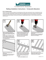
PRIOR TO INSTALLING THE RAILING
IMPORTANT: Please read and follow the instructions in this section before you begin installation of your railing products.
NOTE: Rail lengths will vary slightly due to manufacturing processes. Make sure rails and balusters are cut properly to correct length,
and with hole pattern centered between posts before securing.
NOTE: For best results, cut post sleeves with a carbide-tipped balde, minimum 32-tooth.
□ If using post sleeve moulding, slide the post down into the cove moulding prior to securing any railings (Fig. 1).
Fig. 1
□ Measure the inside distance between properly installed, plumb posts. See Fig. 2 for Line and Stair Railings.
Fig. 2 For Line For Stairs

6
Pre-Installation (continued)
□ Determine length of top and bottom rails, and cut to length. Place the top and bottom rails side-by-side for accurate placement of
the EZ Mounts (JJ). Center the pattern on the rails, spacing the EZ Mounts (JJ) no more than 4.5 in. apart.
Fig. 3
□ Pre-drill holes with a 1/8 in. bit, and fasten EZ Mounts (JJ) to the top and bottom rails using the screws (KK).
NOTE: Delay fastening EZ Mounts with adapters (LL) to the stair railings until after an angle is cut for stair application. See Step 2
“Marking the angles” in the Stair Installation section of this document.
Fig. 4
KK
JJ

7 HOMEDEPOT.COM/VERANDA
Please contact 1-800-230-7547 for further assistance.
Line Rail Installation
1
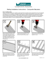
Preparing the bottom rail
□ Position bottom brackets (AA) 1/32 in. – 1/16 in. from the
ends of the bottom rail and mark the hole locations. Ensure
the brackets (AA) are installed on the EZ Mount side.
□ Predrill holes using a 5/32 in. bit and then attach the
brackets (AA) to the bottom rail using 1 in. screws (CC).
DO NOT OVERTIGHTEN THE SCREWS.
A
A
CC
2
Attaching crush blocks
□ Use PVC adhesive to glue crush blocks (1) to the bottom of
the bottom rail at mid-point of rail length to support the rail
in a level position.
□ When installing an 8 foot section, install two crush blocks
at 1/3 points.
1
3
Installing the bottom rail
□ Completely lower the rail into place between the posts and
check to make sure it is level.
□ Once the lower rail is level, mark bracket hole locations.
Remove the rail before pre-drilling the holes.
□ Pre-drill the holes with a 5/32 in. bit, angling slightly
upward and inward to allow for clearance from the rail
once repositioned for securing.
NOTE: Using extended drill bits is recommended to prevent
damage to the rail, and allow a more perpendicular driving
angle.
□ Secure the bottom railing in place using the 2 in. screws
(DD).
AA
DD

8
Line Rail Installation (continued)
4
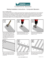
Preparing the top rail
□ Position top brackets (BB) 1/32 in. – 1/16 in. from the
ends of the top rail and mark the hole locations. Ensure
brackets are installed on the side of the top rail with the
EZMounts(JJ).
□ Predrill holes using a 5/32 in. bit and then attach the
brackets (BB) to the top rail using 1 in. screws (CC).
DO NOT OVERTIGHTEN THE SCREWS.
BB
CC
5
Inserting balusters
□ Insert a baluster into the rst EZ Mount(JJ) at both ends of
the bottom rail and one in the middle.
6
Positioning the top rail
□ Carefully position the top rail between the posts and
lower onto the three balusters. Ensure you fully seat the
balusters onto the EZ Mounts.
□ Check the top rail and ensure it is level.
7
Marking and drilling top rail holes
□ Mark the location of the bracket holes.
□ Remove the top rail and balusters. Pre-drill the holes with a
5/32 in. bit, angling slightly upward and inward to allow for
clearance from the rail once repositioned for securing.

9 HOMEDEPOT.COM/VERANDA
Please contact 1-800-230-7547 for further assistance.
Line Rail Installation (continued)
8
Installing the balusters and top rail
□ Insert all balusters into the bottom rail. You do not need to
remove the plugs at the ends of the balusters. Reposition
the top rail over the balusters, and lower into place
between the posts. After the top rail is fully seated, secure
using 2 in. screws (DD). DO NOT OVERTIGHTEN.
NOTE: Using extended drill bits is recommended to prevent
damage to the rail, and allow a more perpendicular driving
angle.
DD
9
Installing the post caps
□ Complete the installation by installing the post cap in place.
You can use a quality exterior adhesive in order to do this,
but note that you will not be able to remove the cap at a
later time once it is glued.

10
Stair Railing Installation
SPECIAL NOTES ON STAIR RAILING
The stair systems are designed for the typical angles created by an approximate 7 in. rise/11 in. run with allowance for accepted
variation in components. The Regency stair system allows for a 30-34 degree stair angle. Building codes are very specic on allowable
angles and widths. It is very important to consult with your local building code ofcials and plan your stair layout accordingly. Ensure that
you leave adequate space for graspable hand rail if applicable. “Dry tting” intermediate post placement will result in easier and better
looking installations and may avoid placement of post mounting brackets in areas where screws cannot attach to the guardrail.
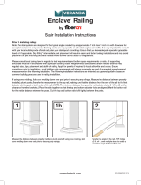
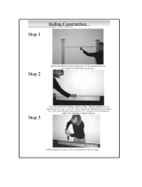
1
Determining the angle for the railing
□ Using a 2 x 4 over the steps to create a consistent angle,
place the bottom rail (1) over the 2 x 4 and mark the end
angles for the bottom rail.
1
2
Marking the angles
□ Align the top rail (1) on top of the bottom rail (2) and mark
the angle of the bottom rail to the top rail.
1
2
3
Cutting the rail angles
□ Cut the top and bottom rails at the marked angles to t
tightly between the posts.
□ Transfer the stair angle to the crush block and cut to the
desired length (consult your local building ofcial for the
proper spacing between the stair tread and the railing).
NOTE: You can now install the EZ Mounts onto the stair
rails. See Figure 4 on page 3 for further clarication and
instruction.
4
Attaching brackets to the rails
□ Place brackets (HH) on each end of the bottom rail (side
without EZ Mounts). Place brackets on each end of the
top rail (side with EZ Mounts). Leave 1/32 in.-1/16 in.
space from the cut edge of the rail. Mark all bracket hole
locations and then drill holes using a 5/32 in. bit.
□ Secure all brackets using the 1 in. screws (FF).
HH
FF

11 HOMEDEPOT.COM/VERANDA
Please contact 1-800-230-7547 for further assistance.
Stair Railing Installation (continued)
5
Preparing the bottom rail installation
□ Place the bottom rail between the posts. Using the bracket
as a guide, mark the location of the holes on the posts.
Remove the rail before pre-drilling the holes.
□ Predrill the holes with a 5/32 in. bit, angling slightly upward
and inward to allow for clearance from the rail once
repositioned for securing.
6
Installing the bottom rail
□ Place crush block on the stair tread surface midway
between the posts and glue to bottom of bottom rail.
□ Secure the bottom rail to the post at both ends using the
2in. screws (GG). DO NOT OVERTIGHTEN.
NOTE: Using extended drill bits is recommended to
prevent damage to the rail, and allow a more perpendicular
driving angle.
GG
7
Positioning the top rail
□ Insert a baluster into the rst and last EZ Mounts in the
bottom rail. Carefully position the top rail between the
posts and engage the EZ Mounts into the balusters. You do
not need to remove the plugs at the ends of the balusters.
□ With the top rail fully seated, and using the top bracket as
a guide, mark the location of the holes. Remove the rail
before pre-drilling the holes.
8
Drilling the top rail holes
□ Predrill the holes with a 5/32 in. bit, angling slightly upward
and inward to allow for clearance from the rail once
repositioned for securing.

12
Stair Railing Installation (continued)
9
Installing the top rail
□ Set each baluster over the bottom EZ Mounts. Secure the
top railing using the 2 in. screws (GG). You do not need to
remove the plugs at the ends of the balusters.
NOTE: Using extended drill bits is recommended to
prevent damage to the rail, and allow a more perpendicular
driving angle.
GG
10
Installing the caps
□ Complete the installation by installing the post cap in place.
You can use a quality exterior adhesive in order to do this,
but note that you will not be able to remove the cap at a
later time once it is glued.

Questions, problems, missing parts? Before returning to the store,
call Veranda Customer Service
8 a.m. - 7 p.m., EST, Monday - Friday, 9 a.m. - 6 p.m., EST, Saturday
1-800-230-7547
HOMEDEPOT.COM/VERANDA
Retain this manual for future use.
VER-0119-PKG 2/17
/