Page is loading ...

verandadeck.com
Measure the distance between properly installed, plumb posts. If using cove molding, slide
cove molding down over post prior to securing any railings.
Transfer the angle to the rails. TIP: bridge
a 2 ft. x4 ft. over multiple steps to create a
consistent angle for the bottom rail.
1 1b 2
Stair Installation Instructions
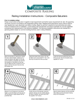
Prior to installing railing:
Note: The stair systems are designed for the typical angles created by an approximate 7 inch rise/11 inch run with allowance for
accepted variation in components. Building codes are very specific on allowable angles and widths. It is very important to consult
with your local building code officials and plan your stair layout accordingly. Ensure that you leave adequate space for graspable
hand rail if applicable. “Dry fitting” intermediate post placement will result in easier and better looking installations and may avoid
placement of post mounting brackets in areas where screws cannot attach to the guardrail.
Please consult local zoning laws in regards to load requirements and bottom space requirements for rails. All supporting
structures must be in accordance with applicable building codes. Neighborhood associations and/or historic districts may
regulate size, type, placement and ability of railing. Apply for permits if required by local authorities and codes. Ensure
compliance prior to installation. Local building code requirements will always supersede any and all suggested procedures and
measurements in the following installation. The following installation instructions are intended as a general guideline based on
common building practices used in railing installation.
If using cove molding, slide cove molding down over post prior to securing any railings. Measure the distance between properly
installed, plumb posts. Transfer the measurement to the top rail, making sure that the distance from the end of the rail to the first
baluster slot is equal on both ends of the rail. (NOTE: The minimum distance from post to first baluster slot is 2 -1/8 in. (5 cm) for
clearance from the brackets.) Place the rails together so that the top and bottom baluster slots are aligned. Mark the bottom rail
for the inside distance between the posts. Cut the top and bottom rails to fit tightly between the posts.
VER-0066-PKG 2/14

verandadeck.com
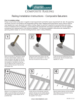
(NOTE: The minimum distance from post
to first baluster slot is 2 -1/8 in. (5 cm) for
clearance from the brackets.) Mark the
bottom and top rails for the inside distance
between the posts. Cut the top and bottom
rails to fit tightly between
the posts.
Secure all brackets with supplied #10 x 1
in. screws.
Using the bracket as a template, locate the
holes and pre-drill with a 1/8 in. drill bit.
Pre-drill the holes with a 1/8 in. bit, angling
slightly upward and inward to allow for
clearance from the rail once repositioned
for securing. Bracket shown for visual
reference only
Place the bracket on the unrouted side of
the bottom rail and the routed side of the
top rail, making sure to leave 1/32 in.-1/16
in. space from the cut edge of the rail. Mark
all bracket holes on rail ends.
Place the bottom rail between the posts.
Using the bracket as a guide, mark the
location of the holes on the posts.
5
86
9
7
10
Transfer the measurement to the top rail,
making sure that the distance from the end
of the rail to the first baluster slot is equal
on both ends of the rail.
Align the top and bottom stair rail baluster
holes to transfer stair angle. Make sure
that when the holes are aligned, that the
stair angle can be continuous across both
pieces.
3 4
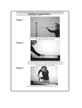
Secure the bottom rail to the post at both
ends using the supplied 2 in. screws.
DO NOT OVER TIGHTEN. NOTE: using
extended drill bits is recommended to
prevent damage to the rail, and allow a
more perpendicular driving angle.
11

verandadeck.com
With the top rail fully seated, and using the
top bracket as a guide, mark the location of
the holes. Remove the top rail & balusters
before pre-drilling.
Fully insert all balusters. NOTE: using
extended drill bits is recommended to
prevent damage to the rail, and allow a
more perpendicular driving angle.
Pre-drill the holes with a 1/8 in. bit, angling
slightly upward and inward to allow for
clearance from the rail once repositioned
for securing. Bracket shown for visual
reference only.
Complete the installation by gluing the post
cap in place with a quality
exterior adhesive.
13b
14
16
15
17
Carefully position top rail over baluster.
Lower until balusters are fully inserted.
NOTE: It may be necessary to cut balusters
to achieve the desired height
Insert a baluster into the first and last holes
in the rail.
12 13a

verandadeck.com
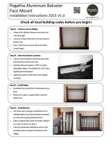
Con el travesaño superior completamente
asentado y utilizando el soporte superior
como guía, marque la ubicación de
los hoyos.
Inserte completamente todos los
balaústres. NOTA: se recomienda
utilizar brocas extendidas para evitar
dañar el travesaño y permitir un ángulo
de arrastre más perpendicular.
Perfore previamente los hoyos con
una broca de 3.2 mm, inclinando
ligeramente hacia arriba y hacia
adentro para dejar un espacio con
respecto al travesaño una vez que este
se haya reposicionado para fijarlo.
Termine la instalación pegando las tapas de los postes en el lugar adecuado con
un adhesivo de calidad para exteriores.
13b 14
16
15
17
Fije el travesaño inferior al poste en
ambos extremos, utilizando los tornillos
de 5 cm suministrados. NO APRIETE
EN EXCESO. NOTA: se recomienda
utilizar brocas extendidas para evitar
dañar el travesaño y permitir un ángulo
de arrastre más perpendicular.
Coloque con cuidado el travesaño
superior sobre el balaústre. Bájelo
hasta que los balaústres estén
completamente insertados.
Introduzca un balaústre en el primero
y en el último hoyo del travesaño.
11 12 13a
/