Page is loading ...

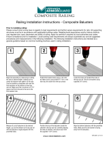
Begin line assembly by measuring &
cutting the rails to desired length, making
sure to center the baluster hole pattern on
the rails.
Use the brackets as templates and mark
the hole locations on the bottom rail and
top sub rail. Make sure that a minimum of
2-3/4" space is left from the end of the rail
to the rst baluster hole.
www.verandadeck.com
VER-0057-LIT 7/13
Railing Installation Instructions - Composite Balusters
Prior to installing railing:
Please consult local zoning laws in regards to load requirements and bottom space requirements for rails. All supporting structures
must be in accordance with applicable building codes. Neighborhood associations and/or historic districts may regulate size, type,
placement and ability of railing. Apply for permits if required by local authorities and codes. Ensure compliance prior to installation.
Local building code requirements will always supersede any and all suggested procedures and measurements in the following
installation. The following installation instructions are intended as a general guideline based on common building practices used in
railing installation.
Measure & cut all balusters to the
desired length.
Lay out the bottom rail & top sub rail with
the balusters roughly aligned with the
predrilled holes.
Predrill the bracket holes using a 1/8" drill
bit. Make sure to only predrill 3/4" or the
hole may be visible from the top surface.
Use a pencil to mark the hole locations,
making sure to leave the bracket 1/32"-
1/16" short from the cut end.
Position the top of the balusters inside the
channel in the top sub rail, carefully aligning
the holes & fastener, and secure each with
1-3/4" (minimum) screws (hardware sold
separately).
Locate the holes and predrill the holes in
the top sub rail.
Install post trim. Secure all brackets using
3/4" screws (hardware sold separately).
(NOTE: Do not over tighten.)
Align the bottom balusters with the
predrilled holes. Make sure the rail channel
is facing away from the balusters.
1
4
2
5
3
6

TIP: only insert 1-3/4" (minimum) screws
into the bottom end of the balusters part
way (hardeware sold separately). This
allows for easier alignment of
upcoming balusters.
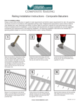
Tighten all screws after each baluster is
secured to bottom rail.
Predrill all holes with a 1/8" drill bit.
Remove the top rail and drill out the sub
rail holes with a 7/32” drill bit. Secure the
rail to assembly using four 1-3/4" screws
(hardware sold separately).
(NOTE: Do not over tighten.)
Install post trim.
Lower the assembly onto crush blocks
cut to the required length. A minimum of 2
crush blocks are needed and the installer
needs to cut crush blocks from an
extra baluster.
Secure the brackets to the posts with 2"
screws (hardware sold separately).
Align the top rail with the assembly.
Finish the assembly by gluing the crush blocks between the 5th and 6th baluster
from each
end
& post caps in place using a quality exterior grade adhesive.
Use a pencil to mark the locations of the
screw holes for the bottom and sub rails
on both ends.
Predrill the sub rail & top rail before the
rst baluster and between the 5th and 6th
baluster
from each end
using a 1/8" drill
bit no deeper than 1-7/8" deep, making
sure to not penetrate the top of the top rail.
(NOTE: this will allow the fastener to snug
the top rail correctly).
www.verandadeck.com
7
10
13
8
11
14
9
12
VER-0057-LIT 7/13

Posts should be plumb in both directions. Measure the distance
between the posts in various locations. The measurement should
not vary by more than 1/16”. Length between posts should not
exceed 70” diagonally.
Begin by supporting the bottom rail uniformly between the
completed post assemblies. Transfer the proper angle to the rail.
www.verandadeck.com
VER-0057-LIT 7/13
Stair Installation Instructions
Prior to installing railing:
Please consult local zoning laws in regards to load requirements and bottom space requirements for rails. All supporting structures
must be in accordance with applicable building codes. Neighborhood associations and/or historic districts may regulate size, type,
placement and ability of railing. Apply for permits if required by local authorities and codes. Ensure compliance prior to installation.
Local building code requirements will always supersede any and all suggested procedures and measurements in the following
installation. The following installation instructions are intended as a general guideline based on common building practices used in
railing installation. Angle used in the installation instructions is based on a common 7” rise x 11” run.
Pre-drill the holes for the brackets
using a 1/8” drill bit.
Center the hole pattern, and cut
both ends to the proper angle.
Drill out the holes with a 7/32” bit at
the same angle as the end cuts. A
minimum of 2-1/2” is needed from
end of rail to rst baluster hole.
Secure the brackets to the top sub-rail & bottom
rail using 3/4” screws (hardware sold separately).
(NOTE: Do not over tighten.)
Place the hinge angle brackets
on the bottom & top sub-rail.
Use a pencil to mark the hole
locations, making sure to
leave the bracket 1/32”-1/16”
short from the cut end.
Transfer the rail angle to both ends of the
balusters and cut to correct length. It may
be necessary to predrill the 1/8” diameter
holes at the ends of the balusters.
Place rails on a smooth, clean surface with
the balusters loosely aligned with the holes.
1 2 3
4 5 6

Starting with the top sub-rail, secure each
baluster using 1-3/4” (minimum) screws
(hardware sold separately). The balusters
will t between the walls on the underside
of the top sub-rail.
Also mark the locations of the top bracket.
Slide trim onto post before attaching rail.
Position the top rail over the assembly.
Secure the bottom rail to the balusters using
1-3/4” (minimum) screws (hardware sold separately).
TIP: don’t fully drive the screws into the bottom rail until
all balusters have been started. This will help in starting
the screws into the predrilled holes in the balusters.
Make sure to snug the screws once all balusters are
started properly. Install post trim prior to step #9.
Predrill bottom holes, and secure using 2” screws (hardware sold separately).
(NOTE: Care should be taken to predrill and insert the screws as perpendicular to the post as
possible. For stairs, it will not be possible to drive all bracket fasteners perpendicular to the
post. The use of a exible shaft or extension may be necessary.)
Lower the top rail into place.
Position and support the
assembled guardrail between
the posts in nal position.
Mark the screw holes with a
pencil for predrilling.
Secure the top bracket using 2” screws
(hardware sold separately).
www.verandadeck.com
7
10
12 13 14
8
11
9
VER-0057-LIT 7/13

Predrill holes at 1/3 points and between the
bracket and rst baluster from each end
using a 1/8” drill bit.
Follow up with a 7/32” drill bit, drilling
through the top sub rail only (this will allow
screws to snug the top rail tightly).
Finish by gluing the post caps on using a
quality exterior adhesive.
Cut 1 crush block from baluster and glue
centered between posts as shown in the
above diagram.
Secure the top rail to the top sub rail using
four 1-3/4” screws (hardware sold separately).
(NOTE: It may be necessary to countersink
using a 3/8” bit, not more than 1/4” deep.)
www.verandadeck.com
15 16 17
VER-0057-LIT 7/13
/