Page is loading ...

DULCOMETER
®
Multi-parameter controller diaLog DACb
Assembly and operating instructions
A2666
EN
Target group: instructed personnel983369 Version: BA DM 234 10/19 EN
Please carefully read these operating instructions before use. · Do not discard.
The operator shall be liable for any damage caused by installation or operating errors.
The latest version of the operating instructions are available on our homepage.

General non-discriminatory approach In order to make it easier to read, this docu‐
ment uses the male form in grammatical struc‐
tures but with an implied neutral sense. The
document is always aimed equally at women,
men and gender-neutral persons. We kindly
ask readers for their understanding in this sim‐
plification of the text.
Supplementary information
Please read the supplementary information in its entirety.
Information
This provides important information relating to the correct operation of the unit or is intended
to make your work easier.
Warning information
Warning information includes detailed descriptions of the hazardous situation, see
Ä Chapter 3.1
‘Labelling of Warning Information’ on page 20
.
The following symbols are used to highlight instructions, links, lists, results and other elements in
this document:
Tab. 1: More symbols
Symbol Description
Action, step by step.
⇨ Outcome of an action.
Links to elements or sections of these instructions or other applicable docu‐
ments.
n
List without set order.
[Button]
Display element (e.g. indicators).
Operating element (e.g. button, switch).
Supplemental directives
2

Symbol Description
‘Display/GUI’
Screen elements (e.g. buttons, assignment of function keys).
CODE
Presentation of software elements and/or texts.
Supplemental directives
3

Table of contents
1 Operating concept................................................................................................................... 9
1.1 Display and keys............................................................................................................ 9
1.2 Functions of the keys .................................................................................................. 13
1.3 Changes the set operating language........................................................................... 14
1.4 Acknowledge fault or warning message ...................................................................... 15
1.5 Key Lock ...................................................................................................................... 15
1.6 Measured variables and measuring inputs................................................................... 16
2 Identity code.......................................................................................................................... 17
2.1 A complete measuring point may comprise the following:........................................... 19
3 Safety and responsibility....................................................................................................... 20
3.1 Labelling of Warning Information.................................................................................. 20
3.2 General Safety Information.......................................................................................... 21
3.3 Intended use................................................................................................................. 22
3.4 User qualification.......................................................................................................... 24
4 Functional Description........................................................................................................... 26
5 Subsequent Extension of Functions ..................................................................................... 27
6 Functions to Backup the Controller's Setting Data................................................................ 29
7 Assembly and installation...................................................................................................... 32
7.1 Scope of supply............................................................................................................ 33
7.2 Mechanical Installation................................................................................................. 33
7.2.1 Wall mounting............................................................................................................ 33
7.2.2 Control Panel Installation.......................................................................................... 35
7.3 Electrical installation..................................................................................................... 38
7.3.1 Specification of the threaded connectors.................................................................. 40
7.3.2 Terminal diagram...................................................................................................... 41
7.3.3 Cable Cross-Sections and Cable End Sleeves......................................................... 55
7.3.4 Wall-mounted and control panel installation.............................................................. 56
7.3.5 Switching of inductive loads...................................................................................... 57
7.3.6 Connect the sensors electrically to the controller...................................................... 58
7.4 Priming to bleeding....................................................................................................... 65
8 Commissioning...................................................................................................................... 66
8.1 Switch-on behaviour during commissioning................................................................. 66
Table of contents
4

8.2 Adjusting the backlight and contrast of the controller display...................................... 67
8.3 Resetting the operating language................................................................................ 67
8.4 Defining metering and control processes..................................................................... 67
8.5 Calibrating conductive conductivity, sensor parameter adjustment............................. 67
9 Configuring measured variables........................................................................................... 69
9.1 Information on the measured variables........................................................................ 71
9.1.1 Measured variable pH [mV]....................................................................................... 71
9.1.2 Temperature.............................................................................................................. 71
9.1.3 Measured variable pH [mA]....................................................................................... 72
9.1.4 ORP [mV], ORP [mA]................................................................................................ 73
9.1.5 Chlorine, bromine, chlorine dioxide, chlorite, dissolved oxygen and ozone.............. 73
9.1.6 Measured variable fluoride........................................................................................ 75
9.1.7 Peracetic acid............................................................................................................ 75
9.1.8 Hydrogen peroxide.................................................................................................... 76
9.1.9 Conductivity [mA]...................................................................................................... 76
9.1.10 Conductive
[conductivity]
......................................................................................... 77
9.1.11 Temperature
[mA]
, (as main measured variable).................................................... 79
9.1.12 mA general.............................................................................................................. 79
9.1.13 Features of the two-channel version....................................................................... 79
10 Calibration............................................................................................................................. 81
10.1 Calibrating the pH Sensor.......................................................................................... 82
10.1.1 Selecting the Calibration Process for pH................................................................. 84
10.1.2 2-Point Calibration of the pH Sensor (CAL)............................................................ 85
10.1.3 pH sensor calibration (CAL) with an external sample (1-point)............................... 89
10.1.4 Calibration of the pH Sensor (CAL) by
[Data Input]
................................................ 92
10.2 Calibrating the ORP Sensor....................................................................................... 95
10.2.1 Selecting the calibration process for ORP............................................................... 95
10.2.2 1-point calibration of ORP sensor (CAL)................................................................. 95
10.2.3 Calibration data for ORP sensor (CAL)................................................................... 97
10.3 Calibrating the Fluoride Sensor.................................................................................. 98
10.3.1 Selection of the calibration process for fluoride....................................................... 98
10.3.2 2-point fluoride sensor calibration (CAL)................................................................. 99
10.3.3 1-point fluoride sensor calibration (CAL)............................................................... 101
10.4 Calibration of Amperometric Sensors....................................................................... 103
10.4.1 Selecting the calibration process for amperometric measured variables.............. 103
10.4.2 Calibrating the slope.............................................................................................. 104
Table of contents
5

10.4.3 Calibration of zero point........................................................................................ 107
10.5 Calibrating the oxygen sensor.................................................................................. 109
10.5.1 Specify the calibration interval............................................................................... 109
10.5.2 Selection of the calibration process for the measured variable O
2
........................ 109
10.6 Measured value [mA general] calibration................................................................. 114
10.7 Calibrating Conductivity
[mA]
................................................................................... 114
10.8 Calibrating conductive conductivity.......................................................................... 115
10.8.1 Calibrating conductive conductivity, sensor parameter adjustment...................... 115
10.8.2 Calibrating conductive conductivity, cell constant................................................. 117
10.8.3 Calibrating conductive conductivity, temperature coefficient................................ 119
10.9 Calibrating temperature............................................................................................ 120
11 Setting the
[Control]
............................................................................................................ 121
11.1 Control parameter [Type]......................................................................................... 127
11.2 Control parameter [System response]...................................................................... 128
11.3 Control parameter [Setpoint].................................................................................... 128
11.4 Control parameter [xp].............................................................................................. 129
11.5 Control parameter [Ti].............................................................................................. 130
11.6 Control parameter [Td]............................................................................................. 130
11.7 Control parameter [Add. Basic load]........................................................................ 130
11.8 Control parameter [Checkout time].......................................................................... 130
11.9 Control parameter [max. ctrl var.]............................................................................. 130
11.10 Interference variable............................................................................................... 130
11.11 Remote setpoint via a 0/4 ... 20 mA analogue signal............................................. 133
11.12 [Parameter switch] via the digital input or [Timer].................................................. 135
12 Setting the
[Limit values]
..................................................................................................... 138
12.1 Function of the limit values....................................................................................... 138
12.2 Setting limit values channel 1................................................................................... 141
12.2.1 Setting [Limit 1]...................................................................................................... 141
12.2.2 Setting [Limit 2]...................................................................................................... 141
12.2.3 Setting [System response].................................................................................... 143
13 Setting the
[Pumps]
............................................................................................................. 144
13.1 Setting [Pump 1]....................................................................................................... 144
14 Setting the
[Relays]
............................................................................................................. 147
14.1 Setting Relay 1......................................................................................................... 147
14.1.1 Function description [Off]...................................................................................... 150
Table of contents
6

14.1.2 Functional description of
[Relay timer]
.................................................................. 150
14.1.3 Function description
[Limit 1]
or
[Limit 2]
.............................................................. 150
14.1.4 Functional description of
[Limit value 1/2 (control variable)]
................................. 150
14.1.5 Function description of
[Cycle]
.............................................................................. 150
14.1.6 Functional description of
[Pulse length (PWM)]
................................................... 151
15 Setting
[digital inputs]
.......................................................................................................... 152
15.1 Setting
[Digital input 1]
............................................................................................. 152
16 Setting the
[mA outputs]
...................................................................................................... 155
16.1 Setting the
[mA outputs]
........................................................................................... 157
17 Function: Data logger.......................................................................................................... 159
17.1 Activating, reading and deleting log books............................................................... 159
17.2 Configuring log books............................................................................................... 160
17.2.1 Using the
[calibration log book]
............................................................................. 160
17.2.2 Using the
[error log book]
...................................................................................... 161
17.2.3 Using the
[Data log book]
(optional)...................................................................... 162
18
[Diagnostics]
........................................................................................................................ 165
18.1 Displaying
[logbooks]
............................................................................................... 165
18.1.1 Displaying the
[Calibration Log Book]
................................................................... 165
18.1.2 Reading the
[Error Log Book]
................................................................................ 165
18.2 Displaying
[simulation]
.............................................................................................. 166
18.3 Display
[Device information]
..................................................................................... 166
18.4 Error messages and warning alerts.......................................................................... 167
18.4.1 Error messages..................................................................................................... 167
18.4.2 Warning messages................................................................................................ 172
18.5 Help texts................................................................................................................. 174
19 Measuring range and technical data................................................................................... 176
19.1 Measuring range/Measured value............................................................................ 176
19.2 Technical data.......................................................................................................... 177
20 Spare Parts and Accessories.............................................................................................. 179
20.1 Spare parts............................................................................................................... 179
20.2 Replacement of Spare Parts Units........................................................................... 180
20.3 Replacing a Fan....................................................................................................... 183
20.4 Accessories.............................................................................................................. 184
21 Disposal of used parts......................................................................................................... 185
Table of contents
7


1 Operating concept
1.1 Display and keys
A1035
1.
Fig. 1: Operating cross (1) / Active keys are displayed in [black] in the display; inactive keys in [grey].
The following path is shown as an example:
Continuous display ➨ ➨ or
[Calibrate]
➨ ➨ or
[Slope]
➨ ➨ .
Continuous display
[Calibrate] [Slope]
A1036
Fig. 2: A display change is made within a sequence of actions.
I. Continuous display 1
II. Display 2
III. Display 3
IV. Display 4
The function of the keys is described in the table
Ä Chapter 1.2 ‘Functions of the keys ’
on page 13
.
➨ = describes as a symbol an action by the operator that leads to a new possibility for an action.
[Naming in the display]
= square brackets contain the name that appears with the identical wording
in the controller display.
Additional information can be obtained via the key.
Operating concept
9

Illumination of the display
In the event of an error with the status [ERROR], the backlight of the display changes from
‘white’ to ‘red’ . This makes it easier for the operator to react to an error.
A2438
Fig. 3: Example of a continuous display when used with one measuring channel (e.g. pH).
A2439
7.55
7.20
0.50
0.30
25
-15
2
1
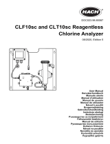
Fig. 4: Example of a continuous display when used with two measuring channels (e.g. pH/chlorine).
If you are using 3 measuring channels, select the desired measuring channel in the display using
or .
A2440
653
700
0.50
0.30
25
-15
2
3
Fig. 5: Example of a continuous display when used with 3 measuring channels (e.g. pH/chlorine/
ORP).
Operating concept
10

If you are using 3 measuring channels, you can use or to display the overall view of the meas‐
uring channels as the fourth view, see .
A2441
7.55
0.30
635
mV
ORP
Kanal 1
Kanal 2
Kanal 3
Fig. 6: Example of a continuous display when used with 3 measuring channels (e.g. pH/chlorine/
ORP) and the display of all 3 measuring channels
Operating concept
11

Parameters in the adjustable menus
Setting of the various parameters in the adjust‐
able menus
No time-controlled menu items
The controller does not exit any menu
items in a time-controlled manner, the
controller remains in a menu item until
this menu item is exited by the user.
1. Select the desired parameter in the dis‐
play using or .
ð
There is an arrow tip in front of the
selected parameter, which indi‐
cates the selected parameter.
2. Press .
ð
You are now in the setting menu for
the desired parameter.
3. You can adjust the desired value in the
setting menu using the four arrow keys
and then save it using .
ð
Range error
If you enter a value that is
outside the possible setting
range, the message
[Range error] appears after
has been pressed.
Pressing
or returns
you to the value to be set.
The controller returns to the menu
once has been pressed.
Cancelling the setting
process
Pressing
returns you to
the menu without a value
being saved.
Operating concept
12

1.2 Functions of the keys
Tab. 2: Functions of the keys
Key Function
Confirmation in the setting menu: Confirms and saves the input values.
Confirmation in the continuous display: Displays all information about saved errors
and warnings.
Back to the continuous display or to the start of the respective setting menu, in
which you are currently located.
Enables direct access to all of the controller's setting menus.
Enables direct access to the controller's calibration menu from the continuous dis‐
play.
Start/Stop of the controller's control and metering function from any display.
To increase a displayed number value and to jump upwards in the operating menu.
Confirmation in the setting menu: Moves the cursor to the right.
Confirmation in the continuous display: Displays further information about the con‐
troller input and output values.
To decrease a displayed number value and to jump down in the operating menu.
Operating concept
13

Key Function
Moves the cursor to the left.
1.3 Changes the set operating language
1. Simultaneously press the keys and
ð
The controller changes to the menu for setting the operating language.
A1482
Language
2
Language
German
Fig. 7: Menu for setting the operating language
2. Now using keys and you can set the desired operating language
3. Confirm your selection by pressing the key
ð
The controller changes back to the continuous display and indicates the selected oper‐
ating language.
Operating concept
14

1.4 Acknowledge fault or warning message
If the controller recognises an error
[Error]
, the control is stopped, the backlight switches to red
lighting and the alarm relay is deactivated. You can access the next value to be set by pressing the
key. In this process, the controller indicates all errors and warnings. The pending alarm mes‐
sages can be selected and, if required, acknowledged/confirmed. If you acknowledge an error, the
alarm relay activates and the backlight switches back to white light. In the bottom part of the display,
the error or warning message that has occurred remains displayed, such as
[Error 01]
, until the
cause has been cleared.
In the event of a warning, e.g. the controller signals that a sensor has not been calibrated yet, further
processing using the controller is possible with or without acknowledgement of the message.
In the event of an error message
[Error]
,
[e.g.]
the controller signals that no sensor is connected,
then after acknowledgement of the message, no further processing is possible using the controller.
You must now rectify the error - for this see the chapter on Diagnostics and Troubleshooting.
Fig. 8: Alarm message, controller stops control
1.5 Key Lock
The controller has a key lock. If the key lock is
activated, the keys cannot be pressed. The key
lock can be activated or deactivated by simulta‐
neously pressing and . An activated key
lock is indicated by the
symbol.
Operating concept
15

1.6 Measured variables and measuring inputs
Measured variable Measuring input Modul type
pH (mV)
Temperature (mV)
ORP (mV)
mV VA
VV
mV/mA measuring input or
mV/mV measuring input
pH (mA)
ORP (mA)
mA general
Bromine
Chlorine
Chlorine dioxide
Chlorite
Fluoride
Oxygen
Ozone
Peracetic acid
Hydrogen peroxide
Conductivity (mA)
Temperature (mA)
mA VA
AA
mV/mA measuring input or
mA/mA measuring input
Conductivity (conductive) L3 Conductive conductivity
Operating concept
16

2 Identity code
Tab. 3: Device identification / Identity code
DAC: DULCOMETER
®
, multi-parameter controller diaLog DACb
Mounting type
W Wall-mounted
S Control panel-mounted
E Spare parts units
Design
00 with ProMinent logo
01 without ProMinent logo
E0 Spare part, processor, complete
E2 Spare part, HMI, complete, with PM logo
E3 Spare part, HMI, complete, Pool design
Operating voltage
4 24 V DC
6 100 - 230 V AC 50/60 Hz
Basic measured variables
VA mV/mA measuring input
AA mA/mA measuring input
VV mV/mV measuring input
L3 Conductive conductivity
Extended functions
0 none
1 Hardware preparation
2 Package 2: interference variable (mA) or external remote setpoint via mA
or pH compensation for chlorine (all acting on channel 1)
Identity code
17

DAC: DULCOMETER
®
, multi-parameter controller diaLog DACb
3 Package 3: 2nd measurement + control, additionally 2 pumps, addition‐
ally 3 control inputs, replaces the D2Ca
4 Package 4: pH compensation for chlorine, only based on measured vari‐
able "VA"
Software default settings
0 no default settings
1 Batch neutralisation
2 Flow neutralisation
3 pH/ORP measurement/control (pH bidirectional, ORP monodirec‐
tional)
4 pH/Cl
2
measurement/control (pH bidirectional, chlorine monodirec‐
tional)
5 pH/ClO
2
measurement/control (pH bidirectional, chlorine dioxide
monodirectional)
6 pH/Cl
2
measurement/control with disturbance variable (pH bidirec‐
tional, chlorine monodirectional)
7 ClO
2
/ORP measurement/control (CIO
2
monodirectional, ORP for
monitoring)
B BOSCH
S Presetting for swimming pool
P Presetting for private swimming pool
Connection of the measured variables
0 all sensor inputs via terminal
1 1x mV input on SN6 socket
2 2x mV inputs on SN6 socket
3 3x mV inputs on SN6 socket
Connection of digital sensors/actuators
0 none
Identity code
18

DAC: DULCOMETER
®
, multi-parameter controller diaLog DACb
Communication interface
X none
A Modbus RTU, terminal
B Profibus DPV1, terminal
E LAN with web server, connection via M12 C-coded
G
PROFINET
®
(2xM12)
Data logger
0 no data logger
1 with data logger (SD card interface + SD card + card
reader)
Hardware extension
0 none
1 Protective RC circuit (relay)
Approvals
01 CE (Standard)
Certificates
0 none
Documentation language: The documentation is available in all the languages pre-set on the con‐
trollers. Other languages are available on request.
2.1 A complete measuring point
may comprise the following:
n Transmitter/Controller DAC (see identity
code)
n Bypass fitting: DGMa..., DLG III ...
n pH sensor (dependent upon the applica‐
tion)
n ORP sensor (dependent upon the applica‐
tion)
n e.g. chlorine, chlorine dioxide, chlorite,
bromine, dissolved oxygen sensor
n Transformer for pH or ORP (depending on
the set evaluation, pH [mA], ORP [mA])
n Sensor cable
Identity code
19

3 Safety and responsibility
3.1 Labelling of Warning Infor‐
mation
Introduction
These operating instructions provide informa‐
tion on the technical data and functions of the
product. These operating instructions provide
detailed warning information and are provided
as clear step-by-step instructions.
The warning information and notes are categor‐
ised according to the following scheme. A
number of different symbols are used to denote
different situations. The symbols shown here
serve only as examples.
DANGER!
Nature and source of the danger
Consequence: Fatal or very serious
injuries.
Measure to be taken to avoid this
danger.
Description of hazard
– Denotes an immediate threatening
danger. If the situation is disre‐
garded, it will result in fatal or very
serious injuries.
WARNING!
Nature and source of the danger
Possible consequence: Fatal or very
serious injuries.
Measure to be taken to avoid this
danger.
– Denotes a possibly hazardous sit‐
uation. If the situation is disre‐
garded, it could result in fatal or
very serious injuries.
CAUTION!
Nature and source of the danger
Possible consequence: Slight or minor
injuries. Material damage.
Measure to be taken to avoid this
danger.
– Denotes a possibly hazardous sit‐
uation. If the situation is disre‐
garded, it could result in slight or
minor injuries. May also be used
as a warning about material
damage.
Safety and responsibility
20
/