Page is loading ...

DULCODOS
®
Pool
DSPa, R01, C01, V01, B01
Assembly and operating instructions
A1114
Original Operating Instructions (2006/42/EC)Part number 985541 BA DD 020 05/12 EN
Please carefully read these operating instructions before use! · Do not discard!
The operator shall be liable for any damage caused by installation or operating errors!
Technical changes reserved.

985541, 1, en_GB
© 2012
ProMinent Dosiertechnik GmbH
Im Schuhmachergewann 5 - 11
69123 Heidelberg
Telephone: +49 6221 842-0
Fax: +49 6221 842-419
email: [email protected]
Internet: www.prominent.com
2

In order to make it easier to read, this document uses the male
form in grammatical structures but with an implied neutral sense. It
is aimed equally at both men and women. We kindly ask female
readers for their understanding in this simplification of the text.
Read the following supplementary information in its entirety!
The following are highlighted separately in the document:
n Enumerated lists
Instructions
ð
Results of the instructions
Information
This provides important information relating to the cor‐
rect operation of the system or is intended to make
your work easier.
Safety information
Safety information are provided with detailed descriptions of the
endangering situation, see
Ä Chapter 3.2 ‘Explanation of the
safety information’ on page 10
General non-discriminatory approach
Supplementary information
Supplemental instructions
3

Table of contents
1
Identity code.......................................................................... 5
2 About this product................................................................. 7
2.1 Overview of equipment................................................. 7
3 Safety and responsibility....................................................... 9
3.1 Users' qualifications...................................................... 9
3.2 Explanation of the safety information.......................... 10
3.3 General Safety Information......................................... 11
3.4 Correct and proper use............................................... 12
4 Storage and transport......................................................... 14
5
Assembly............................................................................ 15
5.1 Wall mounting............................................................. 15
5.2 Fit the antikink device for the bleed line...................... 16
5.3 Hydraulic installation................................................... 17
5.3.1 Metering system...................................................... 18
5.3.2 Sensors.................................................................... 20
5.4 Electrical installation................................................... 21
6 Start up............................................................................... 22
6.1 Priming and bleeding.................................................. 23
6.2 Adjust the flow sensor switching point........................ 23
6.3 Calibration................................................................... 23
7 Maintenance....................................................................... 29
7.1 Maintenance work....................................................... 29
7.2 Troubleshooting.......................................................... 31
7.3 Disposal of used parts................................................ 31
8 Technical data..................................................................... 32
9 Systems.............................................................................. 34
9.1 Spare parts and accessories...................................... 34
9.2 EC Declaration of Conformity..................................... 35
10 Index................................................................................... 37
Table of contents
4

1
Identity code
DSPa
DULCODOS
®
Pool
Measured variable:
R01 Redox (D1C)
C01 Free chlorine (D1C)
V01 Total chlorine (D1C)
B01 Bromine (D1C)
Hardware auxiliary functions:
0 Standard
Software auxiliary functions:
0 none
Communication interfaces:
0 none
Electrical connection:
A 230 V, 50/60 Hz, European standard plug
B 230 V, 50/60 Hz, Swiss plug
Sensor equipment:
0 with sensors
2 Measured variable R01 without sensors
3 Measured variable C01 without sensors
4 Measured variable V01 without sensors
5 Measured variable B01 without sensors
Version:
0 with logo
1 without logo
Language**:
A Swedish H Swiss
D German I Italian
E English N Dutch
F French P Polish
G Czech S Spanish
Metering pumps for acid / alkali:
0 without metering pumps
Multifunctional valve for acid/alkali pump:
0 none
1
with MFV (only for Beta
®
)
Metering pumps for disinfection:
0 without metering pumps
Identity code
5

DSPa
DULCODOS
®
Pool
1
0.8 l/h DULCO
®
flex for up to 45/10
m
3
/h circulation HB/FB*
2
1.6 l/h DULCO
®
flex for up to
100/20 m
3
/h circulation HB/FB*
3
2.4 l/h DULCO
®
flex for up to
140/30 m
3
/h circulation HB/FB*
4
1.8 l/h alpha for up to 100/20 m
3
/h
circulation HB/FB*
5
3.5 l/h alpha for up to 200/40 m
3
/h
circulation HB/FB*
6
0.9 l/h Beta
®
flex for up to 50/10
m
3
/h circulation HB/FB*
7
2.1 l/h Beta
®
flex for up to 125/25
m
3
/h circulation HB/FB*
8
3.9 l/h Beta
®
flex for up to 225/45
m
3
/h circulation HB/FB*
Multifunctional valve for disinfec‐
tion pump
0 none
1
with MFV (only for Beta
®
and
alpha)
Assembly
0 supplied loose without
assembly plate
1 assembled on a base plate
Certification
0 with CE mark
* Calculated for 12 % sodium-calcium hypochlorite:
n HB = Indoor swimming pool
n FB = Outdoor swimming pool
** Other languages upon request
Identity code
6

2
About this product
DULCODOS
®
Pool metering systems are specifically designed for
the treatment of swimming pool water. Ready mounted, fully-wired
and ready for use, they provide disinfection using chlorine or bro‐
mine.
DULCODOS
®
Pool metering systems are equipped with all neces‐
sary components mounted on a plate.
n Sensors
n Controller
n Metering pumps
2.1
Overview of equipment
A1115
13.
12.
11.
10.
9.
8.
7.
6.
5.
4.
3.
2.
1.
Fig. 1: Overview of equipment based on the example DULCODOS
®
Pool metering system R01 (with all
options and metering pump Beta
®
or DF2a)
1. Redox controller
2. Flow sensor
3. Redox sensor*
4. Flow module with flow sensor
5. Ball valve, inlet side
6. Disinfectant injection valve
7. Sampling tap
8.
Metering pump Beta
®
disinfectant
9 Cable disinfectant level switch (only
with metering pump )
10. Suction assembly disinfectant
11. Metering pump DF2a disinfectant
12. Dirt filter
13. Ball valve, outlet side
Not shown
in figure
Disinfectant multifunctional valve
* To be fitted by the customer. These
components are ready for subsequent
installation, but are supplied sepa‐
rately to avoid damage in transit.
Components P01
About this product
7

2.
1.
4.
A1116
3.
Fig. 2: Control elements for the example DULCODOS
®
Pool
metering system R01 (with all options and metering pumps Beta
®
)
The following are used as control elements:
1. Controller keys and display
2. Flow meter (by scale)
3 Stroke adjustment dial of the metering pump (con‐
cealed with the alpha pump)
4. Ball valve, in-line probe housing, inlet side
(Not shown in
figure)
Multifunctional valve
Control elements e.g. R01
About this product
8

3
Safety and responsibility
3.1
Users' qualifications
WARNING!
Danger of injury with inadequately qualified personnel!
The operator of the plant / device is responsible for
ensuring that the qualifications are fulfilled.
If inadequately qualified personnel work on the unit or
loiter in the hazard zone of the unit, this could result in
dangers that could cause serious injuries and material
damage.
– All work on the unit should therefore only be con‐
ducted by qualified personnel.
–
Unqualified personnel should be kept away from
the hazard zone
Training Definition
Instructed personnel An instructed person is deemed to be a person who has been instructed and,
if required, trained in the tasks assigned to him/her and possible dangers that
could result from improper behaviour, as well as having been instructed in the
required protective equipment and protective measures.
Trained user A trained user is a person who fulfils the requirements made of an instructed
person and who has also received additional training specific to the system
from ProMinent or another authorised distribution partner.
Trained qualified per‐
sonnel
A qualified employee is deemed to be a person who is able to assess the
tasks assigned to him and recognize possible hazards based on his/her
training, knowledge and experience, as well as knowledge of pertinent regula‐
tions. The assessment of a person's technical training can also be based on
several years of work in the relevant field.
Electrician Electricians are deemed to be people, who are able to complete work on elec‐
trical systems and recognize and avoid possible hazards independently based
on his/her technical training and experience, as well as knowledge of pertinent
standards and regulations.
Electricians should be specifically trained for the working environment in
which the are employed and know the relevant standards and regulations.
Electricians must comply with the provisions of the applicable statutory direc‐
tives on accident prevention.
Customer Service depart‐
ment
Customer Service department refers to service technicians, who have
received proven training and have been authorised by ProMinent to work on
the system.
Note for the system operator
The pertinent accident prevention regulations, as well
as all other generally acknowledged safety regulations,
must be adhered to!
Safety and responsibility
9

3.2
Explanation of the safety information
These operating instructions provide information on the technical
data and functions of the product. These operating instructions pro‐
vide detailed safety information and are provided as clear step-by-
step instructions.
The safety information and notes are categorised according to the
following scheme. A number of different symbols are used to
denote different situations. The symbols shown here serve only as
examples.
DANGER!
Nature and source of the danger
Consequence: Fatal or very serious injuries.
Measure to be taken to avoid this danger
Danger!
–
Denotes an immediate threatening danger. If this is
disregarded, it will result in fatal or very serious
injuries.
WARNING!
Nature and source of the danger
Possible consequence: Fatal or very serious injuries.
Measure to be taken to avoid this danger
Warning!
–
Denotes a possibly hazardous situation. If this is
disregarded, it could result in fatal or very serious
injuries.
CAUTION!
Nature and source of the danger
Possible consequence: Slight or minor injuries, mate‐
rial damage.
Measure to be taken to avoid this danger
Caution!
–
Denotes a possibly hazardous situation. If this is
disregarded, it could result in slight or minor inju‐
ries. May also be used as a warning about material
damage.
NOTICE!
Nature and source of the danger
Damage to the product or its surroundings
Measure to be taken to avoid this danger
Note!
–
Denotes a possibly damaging situation. If this is
disregarded, the product or an object in its vicinity
could be damaged.
Introduction
Safety and responsibility
10

Type of information
Hints on use and additional information
Source of the information, additional measures
Information!
–
Denotes hints on use and other useful information.
It does not indicate a hazardous or damaging sit‐
uation.
3.3
General Safety Information
WARNING!
Live parts!
Possible consequence: Fatal or very serious injuries
– Measure: Disconnect the mains power supply prior
to opening the housing
–
De-energise damaged, defective or manipulated
units by disconnecting the mains plug
WARNING!
Unauthorised access!
Possible consequence: Fatal or very serious injuries
– Measure: Ensure that there can be no unauthor‐
ised access to the unit
WARNING!
Operating errors!
Possible consequence: Fatal or very serious injuries
– The unit should only be operated by adequately
qualified and technically expert personnel
–
Please also observe the operating instructions for
controllers and fittings and any other component
groups, such as sensors, measuring water
pumps ...
– The operator is responsible for ensuring that per‐
sonnel are qualified
CAUTION!
Electronic malfunctions
Possible consequence: Material damage to destruction
of the unit
– The mains connection cable and data cable should
not be laid together with cables that are prone to
interference
–
Measure: Take appropriate interference suppres‐
sion measures
Safety and responsibility
11

NOTICE!
Correct and proper use
Damage to the product or its surroundings
– The unit is not intended to measure or regulate
gaseous or solid media
–
The unit may only be used in accordance with the
technical details and specifications provided in
these operating instructions and in the operating
instructions for the individual components
NOTICE!
Correct sensor operation / Run-in time
Damage to the product or its surroundings
– Correct measuring and dosing is only possible if
the sensor is working perfectly
– It is imperative that the run-in times of the sensors
are adhered to
– The run-in times should be allowed for when plan‐
ning initial operation
– It may take a whole working day to run-in the
sensor
– Please read the operating instructions for the
sensor
NOTICE!
Correct sensor operation
Damage to the product or its surroundings
– Correct measuring and dosing is only possible if
the sensor is working perfectly
–
Check and calibrate the sensor regularly
NOTICE!
Compensation of control deviations
Damage to the product or its surroundings
– This controller cannot be used in control circuits
which require rapid compensation (< 30 s)
3.4
Correct and proper use
NOTICE!
Compensation for control deviations
Damage to the product or its surroundings
– The controller can be used in processes, which
require compensation of > 30 seconds
Safety and responsibility
12

NOTICE!
Correct and proper use
The unit is intended to measure and regulate liquid
media. The marking of the measured variables is
located on the controller and is absolutely binding.
The unit may only be used in accordance with the
technical details and specifications provided in this
operating manual and in the operating manuals for the
individual components (such as, for example, sensors,
fittings, calibration devices, metering pumps etc.).
Any other uses or modifications are prohibited.
Safety and responsibility
13

4
Storage and transport
CAUTION!
– Prior to storage or transport, the
DULCODOS
®
Pool metering systems
must be free
from feed chemicals and water
– Rinse out the media carrying parts, including the
tubes using clean, pure water
– Transport and store the DULCODOS
®
Pool
metering systems in their original packaging
– Also protect the packaged DULCODOS
®
Pool
metering systems against damp, exposure to
chemicals and mechanical effects
– Please also observe the operating instructions for
controllers and fittings and other units, such as
sensors, filters, metering pumps ...
Storage temperature: 0 ... 50 °C
Air humidity: < 95% relative air humidity, non-condensing
NOTICE!
If the DULCODOS
®
Pool metering systems are stored
as an assembly with the sensors, then the storage and
transport conditions must be appropriate for the com‐
ponent with the least resistance to external influences.
Ambient conditions for storage and
transport without sensors
Storage and transport
14

5
Assembly
Cleaning the injection valve
Localised increases in pH can occur through the
metering of chlorine into the swimming pool water.
This can result in limescale forming in the injection
valve.
Regularly check, clean and descale the injection valve.
The frequency of this work depends on the usage and
ambient parameters of your system and must be deter‐
mined during operation.
To avoid bursting of the metering hose, with metering
pumps of type alpha and Beta
®
, a multifunctional
valve, identity code characteristic "Multifunctional valve
disinfection pump", must be fitted in the metering line.
5.1
Wall mounting
Secure the metering system perpendicular and upright
on a wall or a stable mounting system.
The metering system should be freely accessible.
Select the mounting height you require so that:
n The controller's display can be easily read
n the controller lid can still be parked in the
[Park position]
(150
mm)
n There is still space for maintenance work beneath the in-line
probe housing (100 mm)
n There is still room for the chemical storage tank (600 mm)
n The fluid level of the full chemical storage tanks is below the
metering pumps
n The maximum priming lift of the metering pumps is not
exceeded.
Assembly
15

10 mm
A0924
1
2
3
4
Fig. 3: Hanger bolt
1 Rawlplug (type dependent on substrate and according to stipu‐
lations of the rawlplug manufacturer)
2 Hanger bolt
3 U-washer
4 Hexagon nut
5.2
Fit the antikink device for the bleed line
A0965
4.
3.
2.
1.
Fig. 4: Fit the antikink device for the bleed line (only SEK liquid
end)
1. Bleed valve for the return line in the storage tank, 6/4 mm
2. Red sleeve
3. Discharge valve for discharge line to injection point, 6/4 - 12/9
mm
4. Suction valve for suction line in storage tank, 6/4 - 12/9 mm
1. Fit the antikink device for the bleed line on the upper valve
(red sleeve)
2. route the bleed hose in the gutter of the antikink device
3. Pull the bleed hose downwards
ð
The bleed hose engages in the antikink device.
Only SEK liquid end (metering pump
Beta
®
for disinfection, right side):
Assembly
16

5.3
Hydraulic installation
A1117
Fig. 5: Indoor swimming pool: hydraulic connection of the swimming pool metering system to the swimming
pool installation
Advantage: "Direct" measured values without depletion
Disadvantage: In-line probe housing can become dirty
Assembly
17

A1118
Fig. 6: Outdoor swimming pool: hydraulic connection of the swimming pool metering system to the swimming
pool installation
Advantage: In-line probe housing cannot become dirty
Disadvantage: Measured values with depletion
5.3.1
Metering system
NOTICE!
Maximum permissible operating pressure of in-line
probe housing
Limit the pressure to a maximum of 2 bar (at 30 °C)
directly at the sample water extraction point using a
pressure reducer, otherwise the maximum permissible
operating pressure of the in-line probe housing will be
exceeded.
Do not allow a back pressure of more than 2 bar
(at 30 °C) to build up at the outlet, otherwise the max‐
imum permissible operating pressure of the in-line
probe housing will be exceeded.
1. With flow sensor: Push the flow sensor into the in-line probe
housing and tighten the reducing nipple and the mounting
clip
2. Route the sample water feed via a ball valve from the filter
circuit to the in-line probe housing, see figures above
3. Route the sample water feed via a ball valve from the filtra‐
tion circuit to the in-line probe housing, see figures above
4. Install a 1/2" straight union on the filtration circuit pipe for
each injection valve
Assembly
18

5. Screw the injection valves into a straight union of the filtration
circuit pipe
1
2
3
4
5
6
A0929
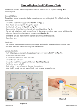
Fig. 7: Connect the tube using the connector kit
1. Valve
2. O-ring
3. Nozzle
4. Clamp ring
5. Union nut
6. Hose
6. Connect the suction hose of the suction assembly to the con‐
nector kit on the liquid end
7. Connect the pressure hose to the pressure connector using
the connector kit
8. Connect the pressure hose to the injection valve using the
connector kit
To ensure reliable measuring and control, the sample
water must be free from air bubbles.
1. Set a flow of 20 ... 60 l/h using the stopcock (read-off at the
top edge of the float).
2. Check the hydraulic leak-tightness of the system (escaping
liquid, continuous air bubbles in the in-line probe housing, ...)
ð
Tighten the threaded connectors if necessary.
1.
Have a collecting vessel at the ready
Open the sampling tap
Testing the hydraulic installation of
the metering system:
Check the system for negative pres‐
sure
Assembly
19

2. If water flows out of the sampling tap, the system is not under
negative pressure and is working correctly
If air is drawn in, this means that there is nega‐
tive pressure in the system. In this case, throttle
the valve at the point at which the sample water
pipe enters the filtration circuit - the pressure
should not exceed 2 bar.
3. Use the stopcock on the sample water drain to finely adjust
the system
5.3.2
Sensors
Observe the operating instructions for the sensors.
1. Close the shut-off valves upstream and downstream of the
in-line probe housing
2. Remove the transparent protective cap from the ball-shaped
end of the redox sensor
3. Manually screw the redox sensors into separate threaded
holes on the in-line probe housing. Then carefully tighten
using an SW 17 open-ended spanner until the threaded con‐
nector is tight
4. Testing the sensors' hydraulic installation: Adjust the flow
using the shut-off valve to 20... 60 l/h
ð
Check whether the threaded connectors on the in-line
probe housing are tight.
Redox sensor installation
Assembly
20
/