Page is loading ...

Sargent Electrical Services Ltd. Copyright 2002
Issue 1 Page 1 of 1 21 October 2002
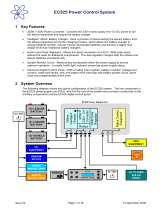
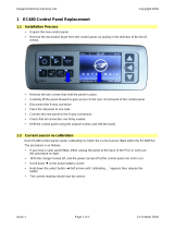
1 EC200 Control Panel Replacement
1.1 Installation Process
· Unpack the new control panel.
· Remove the decorative bezel from the control panel, by pulling in the direction of the BLUE
arrows.
· Remove the two screws that hold the panel in place.
· Carefully lift the panel forward to gain access to the rear circuit board of the control panel.
· Disconnect the 20-way connector and the 2-way temperature probe connector (if fitted).
· Place the old panel to one side.
· Connect the new panel to the 20-way and 2-way connectors.
· Check that all connectors are firmly seated.
· Refit the control panel using the original screws and refit the bezel.
1.2 Current sensor re-calibration (High spec only - V*.*H)
Each High specification (v*.*H) control panel needs 'calibrating' to match the current sensor fitted
within the PSU2007DLX.
The procedure is as follows:
· With the charger turned off, and the power turned off at the control panel (no LED’s on)
· Scroll down ▼ the display until battery current is shown
· Hold down the select button ◄ (left arrow) until 'calibrating….' appears; keep the button
pressed until the battery current reading re-appears.
· Now repeat the process to store the calibration reading.
· Hold down the select button ◄ (left arrow) until 'calibrating….' appears; keep the button
pressed until the battery current reading re-appears.
· The current reading should now be correct.
PDF created with pdfFactory trial version www.pdffactory.com
/