Page is loading ...


Table of Contents
1. EQUIPMENT DESCRIPTION...................................................................................................................................... 1
1.1 Base Station Features ........................................................................................................................................................ 2
1.1.1 Front Panel ........................................................................................................................................................................ 2
1.1.2 Rear and Side Panels ......................................................................................................................................................... 3
1.2 Headset Features ............................................................................................................................................................... 4
1.2.1 Controls and Indicators ..................................................................................................................................................... 4
1.2.2 Correct Wearing of Headsets ............................................................................................................................................ 5
1.2.3 Battery Removal and Replacement ................................................................................................................................... 5
1.3 Battery Charger ................................................................................................................................................................. 6
1.3.1 Battery Charger Power Adapter for Use in the United States ........................................................................................... 6
1.3.2 Battery Charger Power Adapter for Use Outside the United States .................................................................................. 6
1.3.3 Battery Charging ............................................................................................................................................................... 7
2. PREPARATION FOR INSTALLATION ..................................................................................................................... 8
2.1 Tools Required .................................................................................................................................................................. 8
2.2 Interference Prevention ..................................................................................................................................................... 8
2.2.1 Electrical Interference ....................................................................................................................................................... 8
2.2.2 Radio Frequency (RF) Interference ................................................................................................................................... 9
3. EQUIPMENT INSTALLATION ................................................................................................................................. 10
3.1 Base Station Installation .................................................................................................................................................. 10
3.1.1 Install Antennas on Base Station ..................................................................................................................................... 12
3.1.2 Connect Base Station Power Supply ............................................................................................................................... 12
3.1.3 Register Headsets to Base Station ................................................................................................................................... 13
3.1.4 Walk Test for Best Transmission/Reception ................................................................................................................... 15
3.1.5 Mount Base Station on Wall ........................................................................................................................................... 15
3.1.6 Install Remote Antenna Kit (if needed)........................................................................................................................... 15
3.2 Cable Pulling ................................................................................................................................................................... 17
3.3 Outside Microphone and Speaker Installation and Cable Connections ........................................................................... 17
3.3.1 Install DM5 Microphone ................................................................................................................................................. 18
3.3.2 Install SP10 Speaker ....................................................................................................................................................... 19
3.4 Optional SP2000A Speaker/Microphone Installation .......................................................................................................... 21
3.5 Optional External Vehicle Detector Installation ............................................................................................................. 22
3.6 Optional HME Vehicle Detector Board (VDB) Installation ........................................................................................... 22
4. BASE STATION SETTINGS ...................................................................................................................................... 23
4.1 Settings Status ................................................................................................................................................................. 23
4.2 Basic Installer Setups ...................................................................................................................................................... 24
4.2.1 Lane Configuration ......................................................................................................................................................... 25
4.2.2 Auto-Hands-Free ............................................................................................................................................................. 25
4.2.3 Speaker Post .................................................................................................................................................................... 26
4.2.4 Configure Menus............................................................................................................................................................. 26
4.2.5 ClearSound ...................................................................................................................................................................... 27
4.2.6 Diagnostics ...................................................................................................................................................................... 27
4.3 Advanced Installer Setups ............................................................................................................................................... 28
4.3.1 Phone .............................................................................................................................................................................. 28
4.3.2 Line In/Out Routing ........................................................................................................................................................ 29
4.3.3 Radio Options ................................................................................................................................................................. 29
4.3.4 Vehicle Tone ................................................................................................................................................................... 30
4.3.5 Save Installer Settings ..................................................................................................................................................... 30
4.3.6 Language Selection ......................................................................................................................................................... 30
HM Electronics, Inc. is not responsible for equipment malfunctions due to erroneous translation of
its installation and / or operating publications from their original English versions.
© 2014 HM Electronics, Inc.
The HME logo and product names are registered trademarks of HM Electronics, Inc. All rights reserved.
US Patent 7,920,539 B2

4.3.7 Restore Defaults .............................................................................................................................................................. 31
4.4 Network Settings ............................................................................................................................................................. 32
4.4.1 Basic Network Settings ................................................................................................................................................... 32
4.4.2 Advanced Network Settings ............................................................................................................................................ 34
4.4.3 Email / Texting ............................................................................................................................................................... 37
4.5 User Settings ................................................................................................................................................................... 39
4.5.1 Vehicle Detection ............................................................................................................................................................ 39
4.5.2 Operator Mode ................................................................................................................................................................ 40
4.5.3 Message Center ............................................................................................................................................................... 41
4.5.4 Volume Adjustments ....................................................................................................................................................... 58
4.5.5 Register Headsets ............................................................................................................................................................ 59
4.5.6 Service ............................................................................................................................................................................ 59
4.5.7 Store Settings .................................................................................................................................................................. 60
4.5.8 Installer Setup ................................................................................................................................................................. 67
4.5.9 Network .......................................................................................................................................................................... 67
4.5.10 Diagnostics ...................................................................................................................................................................... 67
4.5.11 Early Warning Setting ..................................................................................................................................................... 67
4.6 PC Navigation ................................................................................................................................................................. 68
5. SYSTEM FUNCTIONAL CHECK ............................................................................................................................. 70
6. ROUTINE OPERATION ............................................................................................................................................. 71
6.1 Changing Headset Languages ......................................................................................................................................... 71
6.2 Obtaining Headset Status ................................................................................................................................................ 71
6.3 Single-Lane Operation (one speaker post in one lane) ................................................................................................... 72
6.4 Dual-Lane Operation (two lanes with one speaker post in each lane) .............................................................................. 73
6.5 Tandem Operation (two speaker posts in one lane) ......................................................................................................... 74
6.6 Internal Communication .................................................................................................................................................. 75
6.7 Speed-Team Operation.................................................................................................................................................... 76
6.8 Wired Backup System ..................................................................................................................................................... 76
6.9 Message Center Operation .............................................................................................................................................. 76
7. IN CASE OF PROBLEMS ........................................................................................................................................... 77
8. TO SET BASE STATION FOR SPANISH OR FRENCH LANGUAGE OPERATION ....................................... 80
9. EQUIPMENT SPECIFICATIONS ............................................................................................................................. 81
10. BLOCK DIAGRAM ..................................................................................................................................................... 82
11. BASE INTERFACE DESCRIPTION ......................................................................................................................... 83
11.1 Audio Circuit Board ........................................................................................................................................................ 83
11.2 Switcher Circuit Board .................................................................................................................................................... 84
11.3 Vehicle Detector Circuit Board (Optional) ..................................................................................................................... 84
12. WIRING DIAGRAMS.................................................................................................................................................. 86
13. APPENDIX .................................................................................................................................................................... 97
13.1 Dual-Lane Installer Setup ............................................................................................................................................... 97
13.1.1 Split B ............................................................................................................................................................................. 97
13.1.2 Dedicated Mode .............................................................................................................................................................. 97
13.2 Dual-Lane Message Center Settings ............................................................................................................................... 98
13.2.1 Customer Greeter Messages ............................................................................................................................................ 98
13.2.2 Reminder Messages ........................................................................................................................................................ 98
13.2.3 Alert Messages ................................................................................................................................................................ 98

Figures and Diagrams
dFigure 1. EOS | HD standard equipment ...................................................................................................................................... 1
Figure 2. Base station front panel features ..................................................................................................................................... 2
Figure 3. Base station rear panel features....................................................................................................................................... 3
Figure 4. Headset control buttons and indicator lights ................................................................................................................... 4
Figure 5. Correct wearing of the headset ....................................................................................................................................... 5
Figure 6. Headset battery-release button ........................................................................................................................................ 5
Figure 7. Battery charger power adapter connection ...................................................................................................................... 6
Figure 8. Changing plug in international power adapter ................................................................................................................ 6
Figure 9. AC50 features and battery status guide........................................................................................................................... 7
Figure 10. Typical drive-thru store layout...................................................................................................................................... 10
Figure 11. Typical tandem, Y-lane and dual drive-thru layouts ..................................................................................................... 11
Figure 12. Antenna mounting ........................................................................................................................................................ 12
Figure 13. Power supply connection to base station ...................................................................................................................... 12
Figure 14. Open base station showing four screw holes ................................................................................................................ 15
Figure 15. Remote antenna mounting on wall bracket ................................................................................................................... 16
Figure 16. DM5 Microphone ......................................................................................................................................................... 18
Figure 17. Placement of DM5 Microphone and foam in the foam enclosure ................................................................................. 18
Figure 18. Microphone unit in typical speaker post installation..................................................................................................... 18
Figure 19. SP10 with gasket and cable connector plug .................................................................................................................. 19
Figure 20. SP10 in speaker post, menu board or enclosure ............................................................................................................ 19
Figure 21. Attach brackets to speaker ............................................................................................................................................ 20
Figure 22. Installing the SP2000A ................................................................................................................................................. 21
Figure 23. SP2000A cable connection ........................................................................................................................................... 21
Figure 24. Typical tandem drive-thru layout .................................................................................................................................. 74
Figure 25. S2 switch on Switcher Board ........................................................................................................................................ 76
Figure 26. Base station internal connectors and controls ............................................................................................................... 79
Figure 27. Typical EOS | HD Base Station block diagram ............................................................................................................ 82
Wiring Diagrams ........................................................................................................................................................................... 85
Figure 28. Full-Duplex Drive-Thru System with VDB but no Switcher Board (Lane 1 or Single Lane connections) ................. 86
Figure_29. Full-Duplex Drive-Thru System with VDB but no Switcher Board (Lane 2 connections) .......................................... 87
Figure_30. Full-Duplex Drive-Thru System with VDB, Switcher Board and IC300 (Lane 1 or Single Lane connections) .......... 88
Figure_31. Full-Duplex Drive-Thru System with VDB, Switcher Board and IC300 (Lane 2 connections) .................................. 89
Figure_32. Full-Duplex Drive-Thru System with VDB, Switcher Board and Microphone (Lane 1 or Single Lane connections) 90
Figure_33. Full-Duplex Drive-Thru System with VDB, Switcher Board and Microphone (Lane 2 connections) ......................... 91
Figure_34. Half-Duplex Drive-Thru System with VDB but no Switcher Board (Lane 1 or Single Lane connections) ................ 92
Figure_35. Half-Duplex Drive-Thru System with VDB but no Switcher Board (Lane 2 connections) ......................................... 93
Figure_36. Half-Duplex Drive-Thru System with VDB and Switcher Board (Lane 1 or Single Lane connections) ..................... 94
Figure_37. Half-Duplex Drive-Thru System with VDB and Switcher Board (Lane 2 connections) ............................................. 95
Figure_38. Optional Equipment ..................................................................................................................................................... 96
Illustrations in this publication are approximate representations of
the actual equipment, and may not be exactly as the equipment appears.

IMPORTANT NOTICES
FCC Regulation
This device complies with Part 15 of the FCC rules. Operation is subject to the following two
conditions: (1) This device may not cause harmful interference, and (2) This device must
accept any interference received, including interference that may cause undesired operation.
NOTE: This equipment has been tested and found to comply with the limits for a Class A
digital device, pursuant to Part 15 of the FCC rules. These limits are designed to provide
reasonable protection against harmful interference when the equipment is operated in a
commercial environment. This equipment generates, uses and can radiate radio frequency
energy and, if not installed and used in accordance with the instruction manual, may cause
harmful interference to radio communication. Operation of this equipment in a residential
area is likely to cause harmful interference, in which case the user will be required to correct
the interference at his own expense.
Changes or modifications not expressly approved by HM Electronics, Inc. could void the users
authority to operate this equipment.
The antenna(s) used for the base transmitter must be installed to provide a separation distance of
at least 7.87 inches (20 cm) from all persons, and must not be co-located or operating in
conjunction with any other antenna or transmitter.
This device has been designed to operate with the antennas or antenna kits listed below, and having
a maximum gain of 2dBi. Antennas/Kits not included in this list or having a gain greater than 2dBi
are strictly prohibited for use with this device. The required antenna impedance is 50 ohms.
1. Antenna: NEARSON, S181TR-2450R, 2dBi
2. Antenna Kit: HME, EC20 (P/N G28493-1), 0dBi
3. Antenna Kit: HME, EC10 (P/N G27706-1)
Industry Canada (IC)
This device complies with Industry Canada license exempt RSS standard(s). Operation is
subject to the following two conditions: (1) this device may not cause interference, and (2) this
device must accept any interference received, including interference that may cause undesired
operation of the device.
This device complies with Health Canada’s Safety Code. The installer of this device should
ensure that RF radiation is not emitted in excess of the Health Canada’s requirement.
Information can be obtained at http://www.hc-sc.gc.ca/ewh-sem/pubs/radiation/radio_guide-
lignes_direct-eng.php
“Changes or modifications not expressly approved by the party responsible for compliance
could void the user’s authority to operate the equipment.”

Hereby, HM Electronics, Inc. declares that the EOS|HD is in compliance with the essential
requirements and other relevant provisions of R&TTE Directive 1999/5/EC.
This product operates in the 2400 to 2483.5 MHz frequency range. The use of this frequency
range is not yet harmonized between all countries. Some countries may restrict the use of a
portion of this band or impose other restriction relating to power level or use. You should
contact your Spectrum authority to determine possible restrictions.
Waste Electrical and Electronic Equipment (WEEE)
The European Union (EU) WEEE Directive (2002/96/EC) places an obligation on producers
(manufacturers, distributors and/or retailers) to take-back electronic products at the end of
their useful life. The WEEE Directive covers most HME products being sold into the EU as of
August 13, 2005. Manufacturers, distributors and retailers are obliged to finance the costs of
recovery from municipal collection points, reuse, and recycling of specified percentages per the
WEEE requirements.
Instructions for Disposal of WEEE by Users in the European Union
The symbol shown below is on the product or on its packaging which indicates that this
product was put on the market after August 13, 2005 and must not be disposed of with other
waste. Instead, it is the user’s responsibility to dispose of the user’s waste equipment by
handing it over to a designated collection point for the recycling of WEEE. The separate
collection and recycling of waste equipment at the time of disposal will help to conserve natural
resources and ensure that it is recycled in a manner that protects human health and the
environment. For more information about where you can drop off your waste equipment for
recycling, please contact your local authority, your household waste disposal service or the
seller from whom you purchased the product.


1
1.
EQUIPMENT DESCRIPTION
The EOS|HD is an audio system primarily for use at quick-service restaurants. The
equipment shown below is standard with each EOS|HD. Optional equipment can
be ordered from your local dealer.
As you unpack the EOS|HD, check the packing list for each item to verify receipt of
all equipment and quantities listed.
Optional Equipment
Equipment Product Number
Headset HS6200
Wireless Headset (listen only) HS6000L
Battery BAT51
Headset Earmuff None
Headset Earpiece Cover (disposable) None
Microphone DM5
Telephone Interface TI6000
Vehicle Detector Board VDB102
Vehicle Detector Board (with relay) VDB102R
Vehicle Detector Loop (underground) VDL100
Equipment Product Number
Low-Profile Speaker SP2500LP
Ceiling Speaker MM100
Mode Switch (dual lane) MS10
Remote Speed Team Switch SW2
Switcher Circuit Board None
Antenna Coverage Extension Kit EC10
Extended Coverage Antenna Kit EC20
Remote Antenna Kit
(with 6 ft / 1.83 meter cable) ANT20-6
Remote Antenna Kit
(with 30 ft / 9.14 meter cable) ANT20-30
IMPORTANT!
Before doing anything else, set up the battery charger and
charge the batteries according to the instructions in section 1.3.
Figure 1. EOS | HD standard equipment

2
1.1 Base Station Features
The base station is the electronic heart of the EOS|HD. It contains the circuitry
through which all functions of the drive-thru audio system are channeled.
External base station features are shown in Figures 2 and 3. Internal connectors
and controls are shown in EOS|HD.
1.1.1 Front Panel
The display screen is where all menu selections will be seen for installer setups and
routine operation options. These instructions and the display screens shown are
primarily for single-lane drive-thru operations. For multiple-lane operations, where
additional settings are required, you will be directed to the Appendix.
The LANE STATUS display will be shown on the base station until you press any of
the buttons to select another display. The display screen will go dark after a period
of inactivity; pressing any button will light it up.
The menu-select buttons are used to make selections from the menu on the
display screen.
The Help button can be pushed to obtain information needed in case of problems
with the EOS|HD.
The Back button can be pushed to go back to the previous menu display.
The activity indicators light up as follows:
Lane 1 activity (above the line)
― A1 lights up when the A button is pushed on any Lane 1 headset.
― B1 lights up when the B button is pushed on any Lane 1 headset.
― The car above the line lights up when a car is present at the Lane 1 menu board.
Lane 2 activity (below the line)
― A2 lights up when the A button is pushed on any Lane 2 headset.
― B2 lights up when the B button is pushed on any Lane 2 headset.
― The car below the line lights up when a car is present at the Lane 2 menu board.
Back button
Display screen
Menu-select
buttons
Help button
Activity
indicators
Figure 2. Base station front panel features

3
1.1.2 Rear and Side Panels
When both of the cabinet latches, on top of the cabinet are pressed down at the
same time, the cabinet can be opened by pulling forward and down.
The antenna connectors are for screw-mounting the enclosed antennas.
The four screw holes are used to mount the base station on the wall.
The reset switch is used to perform a soft restart of the base station. It is located
in a small hole on the right side of the base station. To press the reset switch,
carefully push a small pointed object, such as an unfolded paper clip, into the hole.
Cabinet latches
Antenna
connectors
Reset switch
(recessed)
Screw holes
for mounting
on wall
Figure 3. Base station rear panel features

4
1.2 Headset Features
1.2.1 Controls and Indicators
Power On Press and release the power button.
A voice message in the headset will say “headset #, battery full/half/low” and both
the power light and the transmit light will flash red. After a short time, the power
light will change to steady green for Lane 1, and the transmit light will go off. A voice
message will then say “Lane 1 (or 2).”
Power Off Press and hold the power button for about two seconds. A voice message
in the earpiece will say “headset off,” and the power light will go off.
Volume-Up Adjustment — Press and release the volume-up Λ button. Each time
you press the button you will hear a higher pitch beep in the earpiece as the volume
increases. When you reach maximum volume, you will hear a high-pitched double
beep. If you continue holding the volume-up Λ button, the high-pitched beeps will
keep repeating rapidly until you release the button.
Volume-Down Adjustment — Press and release the volume-down V button. Each
time you press the button you will hear a lower pitch beep in the earpiece as the
volume decreases. When you reach minimum volume, you will hear a low-pitched
double beep. If you continue holding the volume-down V button, the low-pitched
beeps will keep repeating rapidly until you release the button.
Transmit
light
Channel “A1”
button
Channel “A2”
button
Channel “B”
button
Volume-up
button
Volume-down
button
Power
light
Power
button
Figure 4. Headset control buttons and indicator lights

5
Battery-release
button (blue)
Battery
1.2.2 Correct Wearing of Headsets
Wear the headset with the microphone on your right or left side next to your mouth.
Adjust the headband and microphone boom as needed.
1.2.3 Battery Removal and Replacement
To change batteries:
When a battery becomes weak, a voice in the headset will say “Change battery.”
When this happens, press the battery-release button and slide the battery out of the
headset as shown in Figure 6.
To replace batteries:
When replacing a battery in the headset, place the end of the battery with the metal
contacts into the headset, in the same position as the battery you removed. Press
the battery carefully in until it snaps in place.
Recharge batteries according to the following instructions.
Hold microphone
boom here to adjust
microphone position
Figure 5. Correct wearing of the headset
Figure 6. Headset battery-release button

6
1.3 Battery Charger
1.3.1 Battery Charger Power Adapter for Use in the
United States
Plug the cord from the +5VDC power adapter into
the top of the battery charger as shown in Figure 7,
and then plug the power adapter into an electrical outlet.
1.3.2 Battery Charger Power Adapter for Use Outside
the United States
An international power adapter is provided with
the battery charger for use in countries outside the
United States. Install the necessary plug on the
adapter as shown in Figure 8. Plug the cord into
the battery charger and then plug the power
adapter into an electrical outlet.
Slide plug
and lift out
Press button
to release
Place tabs on plug into
spaces on adapter
Slide
plug
International adapter plugs
Figure 7. Battery charger power adapter connection
Figure 8. Changing plug in international power adapter

7
1.3.3 Battery Charging
Charge up to four batteries while you are installing the other equipment. Charging
time is about 2.5 hours. When the batteries are fully charged, install them in the
headset as shown in section 1.2.3.
Procedure:
Insert batteries in the charging ports for charging. The batteries can only go into
the charging ports one way. If they do not go in easily, turn them around. DO NOT
force them. Push each battery down into a port until it snaps in place, to be sure it
makes full contact.
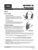
Battery Status Lights:
The battery status lights indicate the charging status, as shown on the battery
status guide at the bottom of the battery charger front panel.
A YELLOW LIGHT stays on steady next to each charging port while the port is empty.
Insert a battery in one of the four charging ports until it clicks in place.
A RED LIGHT will stay on next to a battery while it is charging.
A GREEN LIGHT will go on next to a battery when it is fully charged.
If a YELLOW LIGHT is on next to a battery in a charging port, it means the charge
failed. If this happens: (1) Be sure the battery is pushed all the way into the port until
it snaps into place to make contact. (2) Try charging it in a different port. If it charges
this time, the first charging port may be defective. If the battery does not charge in the
second port, replace it with another battery.
Store up to four fully charged batteries in the storage ports.
Battery status
lights
Battery storage
ports
Battery status
lights
Battery storage
ports
Battery
charging
ports
Battery status guide
Figure 9. AC50 features and battery status guide

8
2.
PREPARATION FOR INSTALLATION
About 3 hours are required for the installation.
Before you begin, coordinate the time of installation with the store owner/manager
to minimize disruption of business.
Be certain electrical power is available.
Be certain some type of compatible vehicle detector loop or other vehicle detector
system has already been installed in the drive-thru lane(s).
2.1 Tools Required
Phillips (cross-point) screwdriver, size #2 wire cutter/stripper
standard (slotted) screwdriver, ⅛ inch (3.2 mm) soldering iron
power drill and drill-bit set rosin-core solder
fish tape, 100 feet (30 meters) electrical tape
2.2 Interference Prevention
CAUTION:
Interference may occur if the audio system is not properly installed.
The following types of interference could occur if precautions are not taken during
installation. Read this section carefully before proceeding.
2.2.1 Electrical Interference
Electrical faults in appliances and other electrical equipment can cause interference
such as static, hum, crackling, buzzing and zip sounds in the headset when the
system is active. Interference caused by electrical faults in lighting systems might
not be noticed immediately, since most lighting systems are controlled by a timer or
light-sensing device.
Faulty Wiring or Components:
Faulty components or electrical wiring in menu boards or speaker posts can cause
symptoms identical to those caused by AM interference. Remove power to the menu
board or speaker post at the circuit breaker until the electrical system can be repaired.
Improper Earth Grounds:
Improper earth grounds in the building can cause random buzzing and zip sounds in
the headset when operating in either channel A or B. Placing a surge protector
between the base station AC adapter and the electrical outlet can eliminate the
problem.
In the event of an electrical power outage —
such as from a lightning storm or power generator failure, if you experience problems with your
HME equipment after the electricity comes on again, unplug the equipment and wait 15 seconds,
then plug it back in.

9
2.2.2 Radio Frequency (RF) Interference
Finding the cause of RF interference is difficult and time-consuming. The following
precautions will help you avoid the most common RF interference problems.
Find the best base station and antenna locations before mounting them.
Solder all joints (including crimp joints) at the speaker location. This is very
important in damp climates
Be certain all connections are tight.
Avoid leaving unshielded wire anywhere in the audio system.
Ground the shield of the outgoing speaker cable. In severe cases of interference,
grounding the shield at the speaker may help.
AM and FM interference may cause similar problems but require different corrective
action. AM interference may increase or decrease at certain times of day, since AM
transmitter power must be reduced in some areas between 5 and 7 PM.
Note the following symptoms carefully to determine the possible cause of
interference. If you need help; in the USA call HME Technical Support at
1-800-848-4468, outside the USA, call your local HME representative.
AM Interference:
Static or hum may be heard in the headset when the system is active. The AM
interference can enter the system through the cables connecting the outside
speaker/microphone to the base station. To block the AM signal, first find out if
there is an AM station in the area, and find out its operating frequency and
transmitter output power. You can then modify the equipment with a network of
inductors and capacitors that will trap the AM signal where it enters the system.
Static, hum and/or voice may be heard in the headset when the system is active or
when transmitting in either channel A or B. The interference can enter the system
at three different locations: the outside speaker cables, the headset/belt-pac
receiver and the base station transmitter. The AM station frequency may completely
suppress or overpower the audio system’s transmitter signal, depending on the
operating frequency, transmitter tower location and output power of the AM radio
station. You may need to move the base station.
FM Interference:
FM interference may cause cracks, pops and other noises to be heard in the headset
when the headset is transmitting on either channel A or B, or when the system is
active.

10
Figure 10. Typical drive-thru store layout
3.
EQUIPMENT INSTALLATION
These instructions are for installation of standard EOS|HD equipment and most
commonly used optional equipment. Specific instructions may also be enclosed
with optional equipment.
If you haven’t already done so, before proceeding with the installation, plug the battery
charger into an AC electrical outlet and charge all the batteries in it while the other
equipment is being installed. Refer to section 1.3.
3.1 Base Station Installation
A typical drive thru QSR building is set up as shown in Figure 10. The numbers in
the following instructions refer to the location numbers in Figure 10. This drawing
is similar to most store layouts. The base station is typically mounted at location
#1. This is also where old equipment is usually found. The order taker is usually at
location #2 in a high volume store. The order
taker headset signal from location #2 must
penetrate two walls to reach the base at location
#1. Signals from the kitchen must only
penetrate one wall to reach the base at location
#1. If there are large pieces of equipment in the
kitchen or speed-team operation is needed
outside at location #6, location #1 may be a poor
choice for mounting the base. For speed team
operations, the signal would have to penetrate
three walls and get by the kitchen equipment to
reach the base at location #1. Coverage in the
store around location #7 and outside at location
#6 may be poor. Don’t forget to check for a
basement. Signals from basements may not
reach the base at location #1.
Things to consider before and during base station installation
The base station should be located where, if you stand with your back to the wall, you
can see most of the work area where the headsets will be used.
The number of walls between the base station and where the headsets will be used
should be minimized.
Sheets of stainless steel on the walls may shield or reflect radio signals.
Outside coverage may be needed for Speed Team operation.
Large windows will allow the signal to pass through and can improve outside coverage.
The antenna coverage area can be extended with the Remote Antenna Kit.
If a system is being replaced, it may not be desirable to use the same mounting location
for the base station as used before, but it may be required in some cases.
If using a power source other than that supplied by HME, the power source must
provide 24 volts DC regulated to +/-5%, be capable of supplying a minimum of 50 watts
of power and be “LPS” rated for safe operation of the unit. The power source must meet
all applicable local regulatory requirements.

11
If outside coverage is not needed, mounting the base at locations #3, #4 or #5 is best.
Headset signals from most work areas would thereby require no wall penetration.
Other work and seating areas may require signals to penetrate one wall. In this case,
the remote antenna kit can be used. The antenna may not need to be mounted far
from the base station unless a large piece of equipment causes a dead spot.
The EOS|HD base uses two antennas to avoid multi-path dropouts. Both antennas
transmit and receive signals. The antenna coverage area can be improved by
mounting one antenna away from the base. The base will select the antenna that
gives the best signal to a particular location.
If outside coverage is required for speed team coverage, mount the base as close as
possible to the wall that faces the desired coverage area. In this case, mounting the
base at location #5 to cover location #6 will minimize wall penetrations. Stores with
a large window near the base will have better outside coverage if the base is facing
the windows. If there are large windows along the wall next to location #6 outside
coverage will be enhanced. Also consider in-store coverage. If the base is located in
the best location for inside and outside coverage, but the coverage outside is still
spotty then the antenna extension cable needs to be run outside the store. In this
case, hanging the antenna under an eve next to the desired area will cover that side
of the store very well. Another approach is to go up through the roof and have the
antenna overlook the desired side area. This approach overcomes obstacles, like
walls, that may shadow the signal when the antenna is at a lower height.
Discuss the location of the base station with the store owner or manager. It should
be mounted less than 10 feet (3 meters) from an available electrical outlet, and away
from grease and large metal objects. Also, it should be mounted near eye level, so
the display screen will be easily visible and the control buttons will be accessible.
The base transmitter antenna(s) must be installed where they will be at least 7.87
inches (20 cm) from all persons, and will not be near any other antenna or
transmitter. The remote antenna kit should be used to extend the coverage area if
needed. See section 3.1.6.
Tandem, Y-Lane or Dual Drive-Thru
For tandem, Y-lane or dual drive-thrus, a vehicle detector and an outside speaker
and microphone will be installed for each order point, and cables pulled as
described in sections 3.2 and 3.3.
Figure 11. Typical tandem, Y-lane and dual drive-thru layouts

12
Type A:
Type B:
3.1.1 Install Antennas on Base Station
Locate the two enclosed antennas, and install them
by screwing them onto the base station antenna
connectors, as shown in Figure 12.
3.1.2 Connect Base Station Power Supply
You may have Type A or Type B power supply, as illustrated in Figure 13.
Connect the power supply to the base station and an AC electrical outlet according
to the numbered instructions for your type power supply, as shown in Figure 13.
If necessary, refer also to the wiring diagrams in Figures 28-38.
Note: If using a power source other than that supplied by HME, it must provide 24
volts DC regulated to +/-5%, be capable of supplying a minimum of 50 watts of power
and be “LPS” rated for safe operation of the unit. The power source must meet all
applicable local regulatory requirements.
Figure 12. Antenna mounting
Figure 13. Power supply connection to base station
/