Page is loading ...

CELLCOMSL™ SERIES UNIVERSAL
ALARM COMMUNICATOR
INSTALLATION AND PROGRAMMING GUIDE

Digital Monitoring Products
CellComSL
Series Universal Communicator Install/Programming Guide
ii
FCC NOTICE
This equipment has been tested and found to comply with the limits for a Class B digital device, pursuant to part 15 of
the FCC Rules. These limits are designed to provide reasonable protection against harmful interference in a residential
installation. This equipment generates, uses and can radiate radio frequency energy and, if not installed and used
in accordance with the instructions, may cause harmful interference to radio communications. However, there is no
guarantee that interference will not occur in a particular installation. If this equipment does cause harmful interference to
radio or television reception, which can be determined by turning the equipment off and on, the user is encouraged to try
to correct the interference by one or more of the following measures:
• Reorient or relocate the receiving antenna.
• Increase the separation between the equipment and receiver.
• Connect the equipment into an outlet on a circuit different from that to which the receiver is connected.
• Consult the dealer or an experienced radio/TV technician for help.
Changes or modications not expressly approved by the party responsible for compliance could void the user’s authority to
operate the equipment.
If necessary, the installer should consult the dealer or an experienced radio/television technician for additional
suggestions. The installer may nd the following booklet, prepared by the Federal Communications Commission, helpful:
“How to identify and Resolve Radio-TV Interference Problems.”
This booklet is available from the U.S. Government Printing Ofce, Washington D.C. 20402
Stock No. 004-000-00345-4
© 2015 Digital Monitoring Products, Inc.
Information furnished by DMP is believed to be accurate and reliable.
This information is subject to change without notice.
The antenna(s) used for this transmitter must be installed to provide a separation distance of at least 20 cm from all
persons.
THIS DEVICE COMPLIES WITH PART 15 OF THE FCC RULES. OPERATION IS SUBJECT TO THE FOLLOWING TWO CONDITIONS: (1)
THIS DEVICE MAY NOT CAUSE HARMFUL INTERFERENCE, AND (2) THIS DEVICE MUST ACCEPT ANY INTERFERENCE RECEIVED,
INCLUDING INTERFERENCE THAT MAY CAUSE UNDESIRED OPERATION.
Industry Canada
This device complies with Industry Canada license-exempt RSS standard(s). Operation is subject to the following two
conditions: (1) this device may not cause interference, and (2) this device must accept any interference, including
interference that may cause undesired operation of the device.
Le présent appareil est conforme aux CNR d’Industrie Canada applicables aux appareils radio exempts de licence.
L’exploitation est autorisée aux deux conditions suivantes : (1) l’appareil ne doit pas produire de brouillage, et (2)
l’utilisateur de l’appareil doit accepter tout brouillage radioélectrique subi, même si le brouillage est susceptible d’en
compromettre le fonctionnement.
Caution Notes
Throughout this guide you will see caution notes containing information you need to know when installing the
c
ommunicator. These cautions are indicated with a yield sign. Whenever you see a caution note, make sure you
completely read and understand its information. Failing to follow the caution note can cause damage to the
equipment or improper operation of one or more components in the system.

CellComSL
Series Universal Communicator Installation and Programming Guide Digital Monitoring Products
iii
TABLE OF CONTENTS
Table of Contents
Description ....................................................................................................................... 1
What is Included ............................................................................................................... 1
System Components ............................................................................. 1
1.1 Terminals ............................................................................................................... 1
Power Connection Terminals ................................................................................... 1
Control Panel Standby Power .................................................................................. 1
Zones 1-4 .............................................................................................................. 1
Dialer Connection .................................................................................................. 2
1.2 Programming (PROG) Connection ............................................................................ 2
1.3 TAMPER ................................................................................................................ 2
1.4 RESET Button ........................................................................................................ 2
1.5 LOAD Button .......................................................................................................... 2
399 Programming Cable ......................................................................................... 2
Model 400 USB Flash Module .................................................................................. 2
1.6 Backlit Logo ........................................................................................................... 3
Mounting the CellComSL Series Communicator .................................... 4
2.1 Selecting a Location ............................................................................................... 4
Applications ........................................................................................... 4
3.1 CID
Dialer Connection ..............................................................................................4
3.2 Zones 1 - 4 Input Connection .................................................................................. 5
3.3 Zone 4 Bell Connection ........................................................................................... 6
3.4 Ademco/Honeywell ECP Connection ......................................................................... 7
Accessing Programming on the Ademco/Honeywell Panel ......................................... 7
Conguring Communication with the Ademco/Honeywell Panel and the CellComSL ..... 7
User Codes in the Ademco/Honeywell Panel ............................................................. 8
Remote Arming/Disarming ................................................................... 9
4.1 DMP Virtual Keypad App / Virtual Keypad Browser .................................................... 9
Programming the
CellComSL
Series Universal Alarm Communicator . 10
5.1 Before You Begin ..................................................................................................10
Programming Information Sheet ............................................................................10
5.2 Getting Started .....................................................................................................10
Accessing the Programmer ....................................................................................10
5.3 Programming Menu ...............................................................................................10
5.4 Reset Timeout ......................................................................................................10
5.5 Special Keys ..........................................................................................................11
CMD (command) Key ............................................................................................11
Back Arrow (<—) Key .............................................................................................11
Select Keys/Areas .................................................................................................11
5.6 Entering Alpha Characters ......................................................................................11
5.7 Entering Non-Alpha Characters ...............................................................................12
5.8 Keypad Displays Current Programming....................................................................12
Initialization ........................................................................................ 13
6.1 Initialization ..........................................................................................................13
6.2 Clear All Codes ......................................................................................................13
6.3 Clear All Schedules ................................................................................................13
6.4 Clear Events .........................................................................................................13
6.5 Clear Zone Programming .......................................................................................13
6.6 Clear Communication ............................................................................................13
6.7 Set to Factory Defaults ..........................................................................................13
Communication ................................................................................... 14
7.1 Communication .....................................................................................................14
7.2 Account Number ...................................................................................................14
7.3 Transmission Delay ................................................................................................14
7.4 Communication Type .............................................................................................14
7.5 Test Time .............................................................................................................14
7.6 Test Days .............................................................................................................14

Digital Monitoring Products
CellComSL
Series Universal Communicator Installation and Programming Guide
iv
TABLE OF CONTENTS
7.7 Cell Check In ........................................................................................................14
7.8 Fail Time ..............................................................................................................14
7.9 Receiver 1 Programming ........................................................................................14
7.10 Alarm Reports .......................................................................................................14
7.11 Supervisory/Trouble Reports ..................................................................................14
7.12 Opening/Closing and User Reports .........................................................................14
7.13 Test Report ...........................................................................................................14
7.14 First IP Address .....................................................................................................14
7.15 First IP Port ..........................................................................................................15
7.16 Second IP Address ................................................................................................15
7.17 Second IP Port ......................................................................................................15
7.18 Receiver 2 Programming ........................................................................................15
7.19 Alarm Reports .......................................................................................................15
7.20 Supervisory/Trouble Reports ..................................................................................15
7.21 Opening/Closing and User Reports .........................................................................15
7.22 Test Report ...........................................................................................................15
7.23 First IP Address .....................................................................................................15
7.24 First IP Port ..........................................................................................................15
7.25 Second IP Address ................................................................................................15
7.26 Second IP Port ......................................................................................................15
Messaging Setup ................................................................................. 16
8.1 Messaging Setup ...................................................................................................16
8.2 Enable Messaging .................................................................................................16
8.3 System Name .......................................................................................................16
8.4 Destination 1 ........................................................................................................16
8.5 Destination 1 User Number ....................................................................................16
8.6 Destination 2 ........................................................................................................16
8.7 Destination 2 User Number ....................................................................................16
8.8 Destination 3 ........................................................................................................16
8.9 Destination 3 User Number ....................................................................................16
8.10 O/C SMS ...............................................................................................................16
8.11 Monthly Limit ........................................................................................................16
Remote Options .................................................................................. 17
9.1 Remote Options ....................................................................................................17
9.2 Remote Key ..........................................................................................................17
9.3 Remote Disarm .....................................................................................................17
9.4 App Key ................................................................................................................17
System Reports ................................................................................... 17
10.1 System Reports .....................................................................................................17
10.2 Opening/Closing Reports .......................................................................................17
10.3 Zone Restoral Reports ...........................................................................................17
System Options ................................................................................... 17
11.1 System Options .....................................................................................................17
11.2 Entry Delay 1 ........................................................................................................17
11.3 Exit Delay .............................................................................................................17
11.4 Cross Zone Time ...................................................................................................18
11.5 Power Fail Delay ....................................................................................................18
11.6 Swinger Bypass Trips .............................................................................................18
11.7 Reset Swinger Bypass ............................................................................................18
11.8 Time Changes .......................................................................................................18
11.9 Keypad Input ........................................................................................................18
Output Options .................................................................................... 19
12.1 Output Options .....................................................................................................19
12.2 Cutoff Outputs ......................................................................................................19
12.2.1 Output Cutoff Time ...............................................................................................19
12.3 Communication Failure Output ...............................................................................19
12.4 Armed Output .......................................................................................................19

CellComSL
Series Universal Communicator Installation and Programming Guide Digital Monitoring Products
v
TABLE OF CONTENTS
12.5 Remote Arming Output ..........................................................................................19
12.6 Heat Saver Temperature (
CellComSL
CZ only) ..........................................................19
12.7 Cool Saver Temperature (
CellComSL
CZ only) ...........................................................19
Area Information ................................................................................. 19
13.1 Area Information ...................................................................................................19
13.2 Area Number ........................................................................................................19
13.3 Area Name ...........................................................................................................19
13.4 Automatic Arming .................................................................................................20
13.4.1 Bad Zones ............................................................................................................20
13.5 Automatic Disarming .............................................................................................20
Zone Information ................................................................................ 20
14.1 Zone Information ..................................................................................................20
14.2 Zone Number ........................................................................................................20
14.3 Zone Name ...........................................................................................................20
14.4 Zone Type ............................................................................................................20
14.5 Area Assignment ...................................................................................................20
14.6 Arming Zone Assignment .......................................................................................21
14.7 Style ....................................................................................................................21
14.8 Next Zone .............................................................................................................21
14.9 Alarm Action .........................................................................................................21
14.10 Disarmed Open .....................................................................................................21
14.11 Message To Transmit .............................................................................................21
14.12 Output Number .....................................................................................................22
14.13 Output Action .......................................................................................................22
14.14 Swinger Bypass .....................................................................................................22
14.15 Cross Zone ...........................................................................................................22
14.16 Receiver Routing ...................................................................................................22
14.17 Zone Number ........................................................................................................22
Stop ..................................................................................................... 23
15.1 Stop .....................................................................................................................23
Set Lockout Code ................................................................................ 23
16.1 Set Lockout Code ..................................................................................................23
Z-Wave Setup ...................................................................................... 24
17.1 Add Z-Wave Devices (ADD) ....................................................................................24
17.2 List Z-Wave Devices (LIST) ....................................................................................24
17.3 RENAME Z-Wave Devices .......................................................................................24
17.4 STATUS of Z-Wave Devices ....................................................................................25
17.5 Remove Z-Wave Devices (REMOVE) ........................................................................25
17.6 Favorites (FAV) .....................................................................................................25
17.7 Adding a FAVORITE ...............................................................................................25
17.8 ADD Devices to FAVORITES ...................................................................................25
17.9 Device Settings in FAVORITES ................................................................................26
Lights ..................................................................................................................26
Doors ...................................................................................................................26
Thermostats .........................................................................................................26
17.10 EDIT Devices in FAVORITES ...................................................................................27
17.11 REMOVE Devices from FAVORITES .........................................................................27
17.12 Transfer Controller (XFER) .....................................................................................27
Transfer Operation: ...............................................................................................27
17.13 Optimize (OPT) .....................................................................................................28
Appendix ............................................................................................. 29
18.1 False Alarm Reduction ...........................................................................................29
System Recently Armed report ...............................................................................29
18.2 Diagnostics Function .............................................................................................29
Cellular Status ......................................................................................................29
Cellular Signal Strength (CELL SIGNAL) ..................................................................29
Cell Roaming Indicator ..........................................................................................29

Digital Monitoring Products
CellComSL
Series Universal Communicator Installation and Programming Guide
vi
TABLE OF CONTENTS
Activate Cell .........................................................................................................29
Panel Settings .......................................................................................................29
Serial Number ......................................................................................................29
Model Number ......................................................................................................29
Firmware Version ..................................................................................................29
Z-Wave Test Option ...............................................................................................30
Contact ID Recvd ..................................................................................................30
Exiting the Diagnostics program .............................................................................30
18.3 Using the 984 Command Function ..........................................................................30
CELL ....................................................................................................................30
18.4 Using the Walk Test ...............................................................................................30
Walk Test..............................................................................................................30
Trip Counter for Walk Test (STD) ............................................................................30
Test End Warning ..................................................................................................30
Failed Zones Display ..............................................................................................30
18.5 Cross Zoning .........................................................................................................31
18.6 Z-Wave Information ...............................................................................................31
18.7 Zone 4 Bell Cadence Information ............................................................................31
18.8 Remote Arming/Disarming for Ademco Vista Control Panels .....................................32
18.9 Ademco Vista 20P to CellComSL for Remote Arming/Disarming .................................33
18.10 DMP XRSuper6 to CellComSL for Remote Arming/Disarming .....................................33
Compliance .......................................................................................... 34
CellComSLCF Commercial Fire Slave Communicator Installation
ANSI/UL 864 ....................................................................................................................34
19.1 Fire Protective Signaling Systems using Internet/Intranet/Cell Networks ....................34
Path 1 Type CELL Primary with no Backup ..............................................................34
19.2 Model 685-R Back Box Installation ..........................................................................34
19.3 CellComSLCF Series for FACP Communication Fail Output .........................................35
New York City (FDNY) Specications.................................................. 36
20.1 Introduction ..........................................................................................................36
20.2 Network and Cellular Communication, Primary and Secondary ..................................36
iComSLF Primary and CellComSLCF Series Backup Programming ..............................36
CellComSLCF Series Primary and iComSLF Backup Programming ..............................36
20.3 Wiring ..................................................................................................................36
20.4 Additional Requirements ........................................................................................36
Specications ...................................................................................... 37
Ordering Information .......................................................................... 37
Dimension and Color ........................................................................... 37
Certications ....................................................................................... 37

CellComSL
Series Universal Communicator Installation and Programming Guide Digital Monitoring Products
1
INTRODUCTION
CellComSL™ Series Universal Alarm Communicator
Description
The
CellComSL
™ Series Alarm Communicator provides a fully supervised alarm communication path for any burglary,
commercial re or residential re control panel. The CellComSL Series can be connected to a control panel’s dialer
output and used to capture Contact ID messages based on SIA DC-05-1999.09-DCS. The CellComSLC has a built-in CDMA
cellular module to send messages to DMP Model SCS-1R or SCS-VR Central Station Receivers. The
c
ommunicator also
provides four input zones and two open-collector outputs for connection to burglary, commercial re or residential re
control panel outputs and zones. The CellComSL Series Communicator Zone 4 allows a connection to the bell output of
an existing control panel. The communicator operates in a variety of applications: CID Dialer Connection, Zones 1-4 Input
Connections, or Zone 4 Bell Connection (See Applications on page 5). The
CellComSL
CZ™ Alarm Communicators include an
onboard Z-Wave controller for home automation applications. The
CellComSL
CF™ Series Fire Alarm Communicator includes
a Red Enclosure and a Model 685-R (Red) Back Box.
What is Included
The
CellComSL
Series Universal Alarm Communicator includes the following:
• PCB with Enclosure
• Hardware Pack
• Dual Band Rubberduck Antenna (Part No. 383)
System Components
1.1 Terminals
Power Connection Terminals
Power is provided from the Nominal 12VDC auxiliary output of the control panel for CellComSLC and
CellComSLCZ. The CellComSLCF Series may be powered from the 12VDC or 24VDC auxiliary output of the control
panel.
OBSERVE POLARITY (See Figure 1 and Backlit Logo)
Using 18 - 22 AWG wire, connect the
communicator
terminal +12 to the +12 or +24 Volt positive terminal on the
control panel auxiliary output
.
Connect the communicator terminal G (Ground) to the negative terminal on the control panel auxiliary output.
Control Panel Standby Power
During a power outage, the CellComSL draws power from the control panel’s backup battery. The CellComSL must
be included in the standby battery calculations for the control panel.
Zones 1-4
Terminals Z1 to Z3, G (Ground), Z4+ and Z4- provide four zones to connect to individual relay outputs on
the control panel. Zone 4 (Z4+ and Z4-) can be connected to the control panel bell output. See Zone 4 Bell
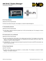
Figure 1: CellComSL Series Communicator
RB
J8
S3 J9
RESET
LOAD
S1
S2
J19
Cell Modem
SYSTEM COMPONENTS

Digital Monitoring Products
CellComSL
Series Universal Communicator Installation and Programming Guide
2
SYSTEM COMPONENTS
Connection.
Open-Collector Outputs
The two outputs, terminals O1 and O2 (see Figure 1), can be programmed to indicate the activity of the zones
or conditions occurring on the system. Open-Collector outputs do not provide a voltage but instead switch-to-
ground the voltage from another source. Maximum voltage is 30VDC @ 50 mA. The outputs can respond to any of
the conditions listed below:
• Activation by zone condition: Steady, Pulse, Momentary, or Follow
• Communication
• Armed area annunciation
• Remote Arming Output
Dialer Connection
Directly connect the telco phone line (tip and ring) from the control panel to the CellComSL Series Universal
Communicator terminal R (Ring) and one into T (Tip) (See CID Dialer Connection).
1.2 Programming (PROG) Connection
A 4-pin PROG header is provided to connect a keypad when using a DMP Model 330
Programming Cable. This provides a quick and easy connection for programming
the
CellComSL
Series Universal Alarm Communicator. For 24VDC applications
using the CellComSLCF Series, connect the keypad using a Model 330-24 4-wire
programming harness with in-line resistor. After programming is complete,
remove the keypad.
If connecting to a 24VDC control panel, do not connect a keypad using a
Model 330 harness! Damage to the keypad could occur.
1.3 TAMPER
The TAMPER button is pressed when the cover of the CellComSL Series
Communicator is secured onto the enclosure. When the cover is removed, the
communicator sends a Tamper Trouble message to the Central Station.
1.4 RESET Button
The RESET button is located on the right side of the circuit board and is used to
reset the communicator microprocessor. After resetting the
communicator,
begin
programming within 30 minutes. If you wait longer than 30 minutes, reset the
communicator
again.
1.5 LOAD Button
The
CellComSL
Series Universal Alarm Communicator rmware can be updated via
the PROG header.
Do not connect a Model 400 to the CellComSLCF if using 24 volt power!
Damage to the Model 400 could occur.
To update the communicator with a new rmware version, complete the
following steps at the protected premise:
399 Programming Cable
1. Connect a DMP 399 Cable from the PROG Header to the serial port of
your PC operating Remote Link and containing the communicator RU le.
2. Start Remote Link and create or open the account that matches the communicator to be updated.
3. Set the Connection Information Type to Direct with a baud rate of 38400 and choose the appropriate
COM port.
4. Select Panel>Remote Update, then select the correct RU le for the communicator.
5. Press and hold the LOAD button, then press and release the RESET button.
6. Release the LOAD button and click <Update> in Remote Link.
7. After the rmware update is completed, remove the 399 cable and press the RESET button to resume
normal operation.
Model 400 USB Flash Module
1. Press and hold the LOAD switch. While holding the LOAD switch, press and release the RESET switch
2. Release the LOAD switch.
3. Connect the USB ash drive containing the .RU le to the Model 400 and connect the assembly to the
CellComSL PROG header. The LED on the Model 400 will ash then display steady green.
4. Press and release the LOAD button on the Model 400 to initiate the rmware update. The LED on
the Model 400 will ash slowly. If the LED displays fast ashes it means the rmware update was
RB
J8
S3 J9
RESET
LOAD
S1
S2
J19
Cell Modem
Figure 2: PROG Port Location
RB
J8
S3
J9
RESET
LOAD
S1
S2
J19
Cell Modem
Figure 3: TAMPER Location
RB
J8
S3 J9
RESET
LOAD
S1
S2
J19
Cell Modem
Figure 4: RESET and LOAD
Button Location

CellComSL
Series Universal Communicator Installation and Programming Guide Digital Monitoring Products
3
SYSTEM COMPONENTS
unsuccessful.
5. The update will take approximately 4.5 minutes and when complete the LED on the Model 400 will
display steady green.
6. Press and release the RESET switch then remove the Model 400 assembly.
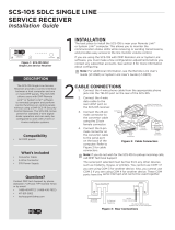
1.6 Backlit Logo
The backlit logo indicates the Power and Armed status of the communicator. Depending on the operation, the
LED displays in Red or Green as listed in the table. The LED indicates the armed state and status of the system
primary power.
Color and Activity Operation
Green Steady Communicator Disarmed, Primary Power OK
No Light No Power
Red Steady Communicator Armed, Primary Power OK

Digital Monitoring Products
CellComSL
Series Universal Communicator Installation and Programming Guide
4
Applications
The CellComSL Series Communicator can be used in a variety of applications:
3.1 CID
Dialer Connection
Directly connect the tip and ring from the control panel to the CellComSL to capture Contact ID messages that
are based on the SIA communication standard DC-05-1999.09-DCS. These messages are then formatted into a
Serial 3 message and sent to a DMP Model SCS-1R or SCS-VR Receiver.
Note: CID Dialer Connection cannot be used when using Zone 4 Bell Connection. Do not connect telephone
company wires to the CellComSL. Remove any connected telephone company wires from the control panel.
INSTALLATION
Mounting the CellComSL Series Communicator
2.1 Selecting a Location
Install the communicator away from metal objects. DO NOT MOUNT THE CELLCOMSL SERIES COMMUNICATOR
INSIDE OR ON A CONTROL PANEL METAL ENCLOSURE (See Figure 5).
Control Panel
Metal Enclosure
Conduit
Conduit
Figure 6: Mounting Screw Locations
RB
J8
S3 J9
RESET
LOAD
S1
S2
J19
Cell Modem
Mounting Screw Locations
Rubber Duck Antenna
SMA
Antenna
Figure 5: Suggested Mounting Locations
Figure 7: Wire Routing Options
RB
J8
S3 J9
RESET
LOAD
S1
S2
J19
RB
J8
S3 J9
RESET
LOAD
S1
S2
J19
Tamper Switch
Mounting the communicator on or near metal surfaces impairs cellular and Z-Wave wireless performance. The
enclosure for the
c
ommunicator should be mounted to the wall using the included #6 screws in the four mounting
holes (See Figure 6). Mount the enclosure in a secure, dry place to protect the communicator from damage due
to tampering or the elements. It is not necessary to remove the PCB when installing the enclosure.
When installing component wires, care must be taken to route all wires in such a manner that they will not
interfere with the TAMPER switch (See Figure 7).
Note: Care should be taken to not damage any PCB components when removing or installing the top cover.
Connect the External Antenna
1. Remove the cover of the universal communicator.
2. Place the rubberduck antenna onto the SMA connector.
3. Using your index nger and thumb, twist the antenna until it is securely tightened. See Figure 6.
APPLICATIONS

CellComSL
Series Universal Communicator Installation and Programming Guide Digital Monitoring Products
5
APPLICATIONS
3.2 Zones 1 - 4 Input Connection
Connect each control panel relay output to a CellComSL Series Communicator zone. For programming purposes,
the zone numbers are 1 - 4. See Figure 9 for Burglary wiring details or Figure 10 for Fire wiring details. The
following are examples of how you might use this application for a burglary or re alarm:
Burglary
Use a normally closed output on a burglary control panel to indicate a burglary alarm. The CellComSL zone
should be programmed with a Zone Name and burglary Zone Type. When the output on the control panel turns
on and trips the CellComSL zone, a message will be sent to an SCS-1R or SCS-VR receiver at Central Station. The
zone name programming could be used to describe which control panel zone indicated a burglary.
Note: Zone 4 can only be used as a standard input zone when not programmed as zone type Auxiliary 2 (A2). See
Zone 4 Bell Connection.
Fire
Use a normally open output on a Fire control panel to indicate a re alarm. The CellComSLCF Series zone should
be programmed with a Zone Name and Fire Zone Type. When the output on the control panel turns on and trips
the CellComSLCF Series zone, a message will be sent to an SCS-1R or SCS-VR receiver at Central Station. The
zone name programming could be used to describe which control panel zone indicated a re.
Use 18-22 AWG for
Power Supply connection
Z3 +
Z4 +
Z4 -
GND
12VDC Aux. Output +
-
Ground
Burglary
Control Panel
The panel or separate power
supply must be 12 Volt Regulated
and Power Limited.
Z1 +
Z2 +
RESET
S1
LOAD
S2
PROG
S
N
+12 G Z1 Z2 Z4-Z4+GZ3 RTO2O1
RB
Normally Open
Common
Normally Closed
Normally Open
Common
Normally Closed
Normally Open
Common
Normally Closed
Normally Open
Common
Normally Closed
J8
J9
S1
S2
S3
1k ohm
1k ohm
1k ohm
1k ohm
MODEL
CellComSLC
Figure 9: CellComSL Series Wiring Diagram for Burglary Zones 1 - 4
Figure 8: CellComSL Series Wiring Diagram for Tip and Ring Connection
Use 18-22 AWG for
Power Supply connection
CONTROL PANEL TIP
CONTROL PANEL RING
12VDC Aux. Output +
-
Ground
Control Panel
The panel or separate power
supply must be 12 Volt Regulated
and Power Limited.
Telephone
Jack
Connector
BELL -
BELL +
RESET
S1
LOAD
S2
BAT
S
N
+12 G Z1 Z2 Z4-Z4+GZ3 RTO2O1
RB
J8
J26
J9
S1
S2
S3
MODEL
CellComSLC
Use 18-22 AWG for
Power Supply connection
Z3 +
Z4 +
Z4 -
GND
12VDC Aux. Output +
-
Ground
Fire
Control Panel
The panel or separate power
supply must be 12 Volt Regulated
and Power Limited.
Z1 +
Z2 +
RESET
S1
LOAD
S2
PROG
S
N
+12 G Z1 Z2 Z4-Z4+GZ3 RTO2O1
RB
Normally Open
Common
Normally Closed
Normally Open
Common
Normally Closed
Normally Open
Common
Normally Closed
Normally Open
Common
Normally Closed
J8
J9
S1
S2
S3
1k ohm
MODEL
CellComSLC
1k ohm
1k ohm
1k ohm
Figure 10: CellComSL Series Wiring Diagram for Fire Zones 1 - 4

Digital Monitoring Products
CellComSL
Series Universal Communicator Installation and Programming Guide
6
APPLICATIONS
3.3 Zone 4 Bell Connection
Zone 4 (Z4+ and Z4-) can be connected to the control panel bell output. This zone detects an alarm condition
on the control panel by monitoring the voltage and cadence timing of the bell output. See Zone 4 Bell Cadence
Information in the Appendix for cadence timing. To enable alarm detection operation, Zone 4 Bell Connection
must be programmed as Zone Type (A2) in Zone Information programming. The type of Cadence sent to the
CellComSL Communicator, the Zone Number, and type of message sent to the SCS-1R or SCS-VR receiver are
listed below:
BELL CADENCE ZONE NUMBER TYPE OF MESSAGE
Steady ZONE 4 BURGLARY
Pulse or Temporal 3 ZONE 5 FIRE
Temporal 4 ZONE 6 EMERGENCY OR
CARBON MONOXIDE
Note: Zone 5 and 6 are automatically generated by the CellComSL Series, using Zone 4’s Zone name to send to
the Central Station. Zones 5 and 6 cannot be preprogrammed in Zone Information.
Note: CID Dialer Connection cannot be used when using Zone 4 Bell Connection.
Use 18-22 AWG
for Power Supply
connection
Z4 +
Z4 -
DMP Panel
MODEL CellComSL
PROG
+12 G Z1 Z2 Z4-Z4+GZ3 RTO2O1
RB
J8
J9
S3
12VDC Aux. Output
+
-
Use 18-22 AWG
for Power Supply
connection
Z4 +
Z4 -
ADEMCO Panel
MODEL CellComSL
PROG
+12 G Z1 Z2 Z4-Z4+GZ3 RTO2O1
RB
J8
J9
S3
12VDC Aux. Output
+
-
BELL -
12VDC BELL +
Use 18-22 AWG
for Power Supply
connection
Z4 +
Z4 -
NAPCO Panel
MODEL CellComSL
PROG
+12 G Z1 Z2 Z4-Z4+GZ3 RTO2O1
RB
J8
J9
S3
12VDC Aux. Output
+
-
BELL -
12VDC BELL +
Use 18-22 AWG
for Power Supply
connection
Z4 -
DSC Panel
MODEL CellComSL
PROG
+12 G Z1 Z2 Z4-Z4+GZ3 RTO2O1
RB
J8
J9
S3
12/24VDC Aux. Output
+
-
BELL -
12/24VDC BELL +
10k ohm
1k ohm (for Supervision)
1k ohm
1k ohm
1k ohm
1k ohm (for Supervision)
2.2k ohm (for Supervision)
Program Zone 4
DO - Alarm
AO - Alarm
Voltages above 1.4VDC
are considered Alarm
Voltages above 1.4VDC
are considered Alarm
Voltages above 1.4VDC
are considered Alarm
Voltages below 0.7VDC
are considered Alarm
Z4 +
Z4 -
24VDC Panel
MODEL CellComSL
PROG
+12 G Z1 Z2 Z4-Z4+GZ3 RTO2O1
RB
J8
J9
S3
1k ohm
Voltages above 1.4VDC
are considered Alarm
1k ohm
Use 18-22 AWG
for Power Supply
connection
12/24VDC Aux. Output
+
-
BELL -
24VDC BELL +
4.7k ohm (for Supervision if required)
Figure 11: Zone 4 Bell Connection

CellComSL
Series Universal Communicator Install/Programming Guide Digital Monitoring Products
7
3.4 Ademco/Honeywell ECP Connection
A CellComSL may be connected to the ECP Bus of an Ademco/Honeywell panel. Figures 12 and 13 detail the
necessary wiring connections for the CellComSL to communicate with the Ademco/Honeywell ECP Bus.
When connected as shown in Figures 12 and 13, the CellComSL provides the following operation:below:
• Arm and disarm the Ademco/Honeywell panel using the Virtual Keypad App and browser (Stay/Away
systems only).
• Receive alarm, trouble, opening/closing and other messages from the panel and send them to the central
station SCS-1R or SCS-VR receivers.
• Add, delete, and change user codes in the Ademco/Honeywell panel.
ECP operation must be enabled in the CellComSL. See Keypad Input in System Options for additional information.
Accessing Programming on the Ademco/Honeywell Panel
The Installer code may be changed in Ademco/Honeywell panels. A new 4-digit Installer code may be entered.
If the Installer code is not known, the following steps describe how to access Programming in the Ademco/
Honeywell panel without an Installer code:
1. Power down and then power up the Ademco/Honeywell panel.
2. Within 1 minute of powering up the Ademco/Honeywell panel, simultaneously press and hold the # and *
on the keypad.
3. The keypad will display Programming.
Conguring Communication with the Ademco/Honeywell Panel and the CellComSL
The following steps describe how to congure Ademco/Honeywell control panels to communicate with the
CellComSL.
1. Program Position * 54: Enter 0. (No signaling delay)
2. Program Position * 55: Enter 1 (Enables communication to CellComSL).
3. Program Position * 65: Enter 0 (To turn off Opening Reports).
4. Program Position * 66: Enter 0 (To turn off Closing Reports).
5. Program Position * 84: Enter 0 (To disable CP01 and allow remote Arm Away).
6. Program Position * 193: Enter 1 0 (Enables CellComSL ECP Bus address).
Note: In the event the Ademco/Honeywell panel fails to communicate with the CellComSL, program Position * 29
to enable the long range radio on the Ademco/Honeywell panel.
APPLICATIONS
CellComSL to ECP Wiring
CellComSL Ademco/Honeywell ECP Bus
+12 Keypad Power
G Keypad GND
Z4+ Data Out
Z4- Data In
Figure 12: CellComSL to Ademco/Honeywell ECP Pinout

Digital Monitoring Products
CellComSL
Series Universal Communicator Install/Programming Guide
8
User Codes in the Ademco/Honeywell Panel
Because the CellComSL duplicates the panel’s user codes, existing user codes in the Ademco/Honeywell panel,
including Master, must be added to the CellComSL. Any new user codes added to the CellComSL from the Virtual
Keypad App will be automatically entered in the Ademco/Honeywell panel. Master level users cannot be added
to the Ademco/Honeywell panel from the CellComSL.
User codes from the Ademco/Honeywell panel that are designated as Master or Partition Master should be
congured as Master codes in the CellComSL.
If the Ademco/Honeywell panel is armed/disarmed from a keypad, the CellComSL reports an opening/ closing
message by user 0 to the central station.
When the CellComSL is armed by the Virtual Keypad App or Browser, the Ademco/Honeywell panel is also armed
and the CellComSL reports an opening message. If opening and closing reports are enabled in the Ademco/
Honeywell panel a duplicate message will also be sent to the central station.
APPLICATIONS
1 2 3 4 5 6 7 8 9 10 11 12 13 14 15 16 17 18 19 20 21 22 23 24 25
++-
HI
HI
HI
LO
LO
LO
LO
HI
HI
LO
LO
HI
HI
LO
LO
HI
TIP
(BROWN)
RING
(GR AY )
TIP
(GREEN)
RING
(RED)
+-
BLACK
RED
SYNC
COM
DATA
(USE SA4120XM-1
CABLE)
1 2 3 4 5 6 7 8
OUT 17
+12 AUX
GND
OUT 18
VISTA 20P ONLY
Ademco Vista 20P
+DC G Z1 Z2 Z3 G Z4+ Z4- O1 O2 T R
RB
J8
S3 J9
RESET
LOAD
S1
S2
J19
+12 G Z1 Z2 Z3 G Z4+ Z4- O1 O2 T R
Figure 13: Ademco Vista 20P ECP to CellComSL

CellComSL
Series Universal Communicator Install/Programming Guide Digital Monitoring Products
9
REMOTE ARMING/DISARMING
Remote Arming/Disarming
4.1 DMP Virtual Keypad App / Virtual Keypad Browser
Using a Smartphone with the DMP Virtual Keypad App or using a computer with the Virtual Keypad Browser
(www.myvirtualkeypad.com), you can connect to the CellComSL Series Communicator to arm Areas, turn Outputs
on and off, and add, edit or remove Users. When using the CellComSLCZ, you can control Z-Wave devices,
Favorites and Rooms.
Figure 14: Virtual Keypad Application can be used to access the CellComSL Series Communicator.
A burglary control panel zone may be programmed as an arming zone and connected to a CellComSL output
(O1 or O2) (See Figure 14). Program the output number in Armed Output or Remote Arming Output in Output
Options of the CellComSL (See Armed Output or Remote Arming Output). The CellComSL Communicator output
connections can be used with any of the applications listed in Applications Section.
Use 18-22 AWG for
Power Supply connection
O1
O2
12VDC Aux. Output
+
-
Control Panel
MODEL CellComSL
PROG
+12 G Z1 Z2 Z4-Z4+GZ3 RTO2O1
RB
GND
Zone 1
Zone 2 Control Panel EOL resistor
Figure 15: Burglary control panel zones connected to the CellComSL Series outputs to
arm and disarm the burglary control panel.

Digital Monitoring Products
CellComSL
Series Universal Communicator Installation and Programming Guide
10
PROGRAMMING INTRODUCTION
Programming the
CellComSL
Series Universal Alarm Communicator
5.1 Before You Begin
Before starting to program, we recommend you read through the contents of this guide. The information in this
document allows you to quickly learn the programming options and operational capabilities of the
CellComSL
Series Universal Alarm Communicator.
After this Introduction, the remaining sections describe the functions of each programming menu items along
with their available options. The
communicator
contains all of its programming information in an on-board
processor and does not require an external programmer.
In addition to this manual, you should also be familiar with the following
documents:
• CellComSL
Series Universal Alarm Communicator User Sheet (LT-1349)
• CellComSL
Series Universal Alarm Communicator Programming Sheet (LT-1333)
Programming Information Sheet
Included with each communicator are the Programming Sheets. These sheets list the various options available
for programming the
communicator
. Before starting, completely ll out the sheets with the programming options
you intend to enter into the
communicator
.
Having completed the programming sheets available while entering data helps to prevent errors and can shorten
the length of time you spend programming. Completed sheets also provide you with an accurate account of the
communicator
’s program you can keep on le for future system service or expansion.
The remainder of the Introduction explains starting and ending a programming session.
5.2 Getting Started
Initializing the
CellComSL
Series
When programming a
communicator
for the rst time or rewriting the entire program of an existing
communicator, use the Initialization function described in Section 6. Initializing clears the communicator’s
memory of any old data and sets the highest numbered user number to user code 99.
Accessing the Programmer
To access the programmer function of the
communicator
:
1. Connect the keypad to the PROG header
2. Press and release the RESET button.
3. Enter the code 6653 (PROG).
4. The keypad displays: PROGRAMMER.
5.3 Programming Menu
You are now ready to start programming the
CellComSL
Series Universal Alarm Communicator. Pressing the CMD
key scrolls you through the programming menu items listed below.
Menu Item Section in This Manual Menu Item Section in This Manual
Initialization 6 Output Options 12
Communication 7 Area Information 13
Messaging Setup 8 Zone Information 14
Remote Options 9 Stop 15
System Reports 10 Set Lockout Code 16
System Options 11
To select a section for programming, press any Select key when the name of that section displays on the keypad.
The detailed instructions for each programming step are found in this guide.
5.4 Reset Timeout
The
CellComSL
Series Universal Alarm Communicator has a feature that requires you to enter the Programmer
within 30 minutes of resetting the communicator. After 30 minutes, if you attempt to program by entering the
6653 (PROG) code, the keypad displays: RESET PANEL. You must reset the
communicator
and enter the program
code within the next 30 minutes.
If you are already in the Programmer and do not press any keys on the programming keypad for 30 minutes, the
communicator
terminates programming. All data entered up to that point is saved in the communicator memory.
Using the STOP function disarms all areas: To exit the communicator’s Programmer you must use the STOP
function. The STOP option is the second to the last option in programming. The Stop function disarms all areas.
The programming session is then terminated and the keypad returns to the Status List or Main Screen.

CellComSL
Series Universal Communicator Installation and Programming Guide Digital Monitoring Products
11
PROGRAMMING INTRODUCTION
5.5 Special Keys
The following special keys/areas are common to all DMP keypads.
CMD (comand) Key
Pressing the CMD key allows you to go forward through the programming menu and through each step of a
programming sec tion. As you go through the programming, the keypad display shows any current programming
already stored in the communicator memory. If no change is required for an option, press the CMD key to
advance to the next step.
The CMD key is also used to enter information into the communicator’s memory such as an IP address or zone
names. Press the CMD key after entering information.
Back Arrow (<—) Key
Use the Back Arrow key to back up one step while programming. The Back Arrow key is also used when an error is
made while entering in formation. Press the Back Arrow key once to erase the last character entered.
Select Keys/Areas
The top row of keys are called the Select keys on Thinline, and Aqualite keypads or Select Areas on Graphic
Touchscreen keypads. Each time you need to press a Select key, the keypad displays the function or options
above one of the keys or in the Select Area. Displaying choices above individual Select keys or in Select Areas
allows them to be used for many different applications. For example, you can enter AM or PM when programming
the automatic test time or answer YES or NO for a system option.
During programming, the Select keys/areas also allow you to change infor mation currently in communicator
memory by pressing the appropriate Select key under or on the display. You then enter the new information using
the keypad data entry digit keys.
When there are more than four re sponse options avail able, press the CMD key to display the next one to four
options. Pressing the Back Arrow key allows you to review the previous four choices.
The Select keys/areas are also used for choosing a section from the pro gramming menu. Press any Select key or
touch the Select Area when the programming section name you want displays.
On Thinline and Aqualite keypads, when instructed to press the rst Select key, press the far left Select key;
the second Select key is the second from the left; third Select key is second from the right; and the fourth Select
key is the far right key. See Figure 16.
On Graphic Touchscreen Keypads, when instructed to press the rst Select key, touch Select Area 1; the second
Select key touch Select Area 2; third Select key touch Select Area 3; and the fourth Select key touch Select
Area 4. See Figure 17.
5.6 Entering Alpha Characters
Some options during programming require you to enter alpha characters. To enter an alpha character, press or
touch the key that has that letter written below it. The keypad displays the number digit of the key. Next, press
the Select key/area that corresponds to the loca tion of the letter under the key. Pressing a different Select key/
area changes the letter. When an other digit key is pressed, the last letter displayed is retained and the process
starts over.
Figure 16: Thinline/Aqualite Select Keys Figure 17: Graphic Touchscreen Select Areas
First Letter
Second Letter
Third Letter
Special Character
(CBA
32-Character Display
Select Area 1
Select Area 3
Select Area 2
Select Area 4

Digital Monitoring Products
CellComSL
Series Universal Communicator Install/Programming Guide
12
5.7 Entering Non-Alpha Characters
To enter a space in an alpha entry, press the 9 digit key followed by the third Select key/area. The three
characters on the 9 digit key are Y, Z, and space. You can also enter the following characters: – (dash), . (period),
* (asterisk), and # (pound sign) using the 0 (zero) key and the four Select keys/areas from left to right. For
example, to enter a – (dash), press the 0 (zero) key and then the left Select key/area. A dash now appears in the
keypad display. The table below shows the character locations for DMP keypads.
Key Number Select Key 1 Select Key 2 Select Key 3 Select Key 4
1 A B C (
2 D E F )
3 G H I !
4 J K L ?
5 M N O /
6 P QR &
7 S T U @
8 V W X ,
9 Y Z space _
0 - . * #
5.8 Keypad Displays Current Programming
Each programming option displayed at the keypad shows the currently selected option in the communicator
memory. These options are either shown as a number, a blank, or a NO or YES. To change a number or blank to a
new number, press any top row Select key or touch any Select Area. The current option is replaced with a dash.
Press the number(s) on the keypad you want to enter as the new number for that option. It is not necessary to
enter numbers with leading zeros. The communicator automatically right justies the number when you press
the CMD key.
To change a programming option that requires a NO or YES response, press the Select key or touch the Select
Area for the response not selected.
For example, if the current option is selected as YES and you want to change it to NO, on Thinline or Aqualite
keypads press the third top row Select key. On Graphic Touchscreen keypads touch Select Area 3. The display
changes to NO. Press the CMD key to display the next option.
PROGRAMMING INTRODUCTION

CellComSL
Series Universal Communicator Installation and Programming Guide Digital Monitoring Products
13
INITIALIZATION
Initialization
6.1 Initialization
This function allows you to set the communicator’s programmed memory back to the
factory defaults in preparation for system programming.
After you select YES to clear a section of memory, the communicator asks if you are sure
you want to clear the memory. This is a safeguard against accidently erasing part of your
programming. No memory is cleared from the programming until you answer YES to the
SURE? YES NO option.
6.2 Clear All Codes
NO leaves existing codes intact.
YES clears the user code memory and assigns the user code number 99 to user 20.
6.3 Clear All Schedules
NO - Leaves existing schedules intact.
YES - Clears all schedules from the programming.
6.4 Clear Events
NO leaves existing event memory intact.
YES clears all event memory currently held in the communicator’s Display Events buffer.
6.5 Clear Zone Programming
NO leaves existing zone information intact.
YES sets all zones in the system to * UNUSED *
6.6 Clear Communication
NO - Leaves existing communication programming intact.
YES - Clears communication to factory defaults.
6.7 Set to Factory Defaults
NO leaves the remainder of the existing communicator programming intact.
YES sets the communicator programming back to factory default selections and clears
all Z-Wave device programming and Favorites from the communicator. Selecting YES
does not clear the event memory, zone, user code information, or schedules.
INITIALIZATION
CODES? NO YES
SURE? YES NO
SCHEDS? NO YES
SURE? YES NO
EVENTS? NO YES
SURE? YES NO
ZONES? NO YES
SURE? YES NO
COMMS? NO YES
SURE? YES NO
DEFAULTS? NO YES
SURE? YES NO
CODES? NO YES
SCHEDS? NO YES
For each section of the panel program you can
initialize, a NO or YES option is provided.
Selecting YES advances you to
a confirmation prompt.
If you select YES, the panel initializes that section of
the program and advances you to the next prompt.
If you select NO, the panel advances you to the next
section prompt but does not initialize that section of
the program.
SURE? YES NO
Selecting NO
advances you to
the next prompt.

Digital Monitoring Products
CellComSL
Series Universal Communicator Installation and Programming Guide
14
COMMUNICATION
Communication
7.1 Communication
The Communication section allows you to congure the communication settings for the
CellComSL
Communicator. After choosing the Communication Type, continue through the
list of options.
7.2 Account Number
Enter the account num ber sent to the receiver.
The range of account numbers is 1 to 65535. For account numbers of four digits or less,
you do not have to enter leading zeros. The
c
ommunicator automatically right justies
the account number.
7.3 Transmission Delay
Enter the number of seconds (15 to 45 seconds) the communicator waits before sending
burglary alarm reports to the receiver. Enter 0 (zero) to disable this function. The
default is 0.
7.4 Communication Type
The
c
ommunicator uses CELL communication to DMP Model SCS-1R or SCS-VR Receivers.
7.5 Test Time
Press CMD to display the Test Time. Enter the time of day the communicator sends the
test report to the SCS-1R or SCS-VR Receivers. Use entries between 12:00 to 11:59 and
then choose AM or PM. To enable daily tests from the host panel, leave the time blank
and enable test reports for receiver 1 (see 7.13) and/or for receiver 2 (see 7.22).
7.6 Test Days
Enter how often the panel test report is sent to the receiver. Enter from 1 to 60 days.
Enter zero to disable the test report. Default is 1 (one) day. These options only display if
a test time is entered.
7.7 Cell Check In
Check-in reports are a method of supervising the panel for communication with the
receiver.
Enter the number of minutes between check-in reports. Select from 0 or 3-240 minutes.
Enter 0 (zero) to disable the check-in option. Default is 0.
Note: If Cell Check-in option is used, additional cell charges may apply.
7.8 Fail Time
Fail Time allows the SCS-1R or SCS-VR receiver to miss a dened number of check-ins
before logging that the panel is missing. For example, if CELL CHECKIN is 20 and FAIL
TIME is 30, the SCS-1R receiver only indicates a Panel Not Responding after 30 minutes.
The FAIL TIME must be equal to or greater than the CELL CHECKIN minutes: If the
CHECKIN is 20 minutes, the FAIL TIME must be 20 or more. The maximum FAIL TIME is
240 minutes. Select from 0 or 3-240 minutes. The default FAIL TIME is 240 minutes.
7.9 Receiver 1 Programming
Allows you to set the options for the rst receiver the
c
ommunicator attempts
to contact when sending reports from the host panel and/or the CellCom/iCom
communicator. The
communicator
supports communication to two receivers.
7.10 Alarm Reports
YES enables Abort, Alarm, Alarm Restoral, Alarm Bell Silenced, Ambush, Exit Error, and
System Recently Armed reports to be sent to this receiver. Default is YES
7.11 Supervisory/Trouble Reports
YES enables Supervisory, Trouble, Trouble Restoral, Force Armed, and Fault reports to be
sent to this receiver. Default is YES.
7.12 Opening/Closing and User Reports
YES enables Opening/Closing, Schedule and Code Changes, and Bypass reports by user to
be sent to this receiver. Default is YES.
7.13 Test Report
Enter YES to enable the Recall Test report from the host panel and/or CellCom
communicator to be sent to this receiver.
7.14 First IP Address
Enter the rst (primary) IP address where the
c
ommunicator sends cell messages. Enter
all 12 digits and leave out the periods. For example, enter IP address 192.168.0.250 as
192168000250. The periods display automatically.
COMMUNICATION
ACCOUNT NO:
XMIT DELAY: 0
COMM TYPE: CELL
TEST TIME
00:00 AM
CELL TST DAYS: 1
CHECKIN: 0
FAIL TIME: 240
RECEIVER 1 PROG
ALARM NO YES
SPV/TRBL NO YES
O/C USER NO YES
TEST RPT NO YES
FIRST IP ADDR
000.000.000.000
/