Page is loading ...

V1.98 21/06/06
.
X20/X15/X10 Operators Manual
Spray Rate Control
A2677 V1.98 1.4
W133

V1.98 21/06/06V1.98 21/06/06
.
Page 2
As with any computer operated equipment, software and/or hardware is in many cases changed and upgraded
over the life of the equipment.
KEE Technologies software engineers are constantly working on software enhancements which will provide you
with many additional benefits and features in the future.
The ZYNX System will keep on evolving! ...to ultimately improve your ‘bottom line’!
KEE Technologies personnel have records of all changes implemented to your system with the subsequent serial
number.
To keep this Operator’s manual “alive” and current with your equipment and software versions you
will need to administer and document the evolution of your ZYNX System in this manual.
In some cases we will provide you with software upgrades and additional/ replacement pages to add to this
manual. With major software upgrades we may provide you with a completely new manual for the
corresponding ZYNX Solution.
When talking to KEE Support staff, always have this manual with you, as we may ask you what version manual
you are currently looking at to ensure we all talk the same language. For this purpose all pages are coded as
follows.
Page number Date when written Software version
Below is space provided to keep records of any software and hardware upgrades you may have received.
Type of upgrade (software or hardware) Version Date Manual upgraded
09/06
09/06
V1.98
V1.98
21/06/06
21/06/06
ZYNX X20 Sprayer Software (ex factory)
ZYNX X15 Sprayer Software (ex factory)
A
B C

Contents
Page 3
V1.98 21/06/06
V 1.86
IINNSSTTAALLLLAATTIIOONN
1.0
FFoorr
AALLLL
IInnssttaallllaattiioonnss
aanndd
SSeerrvviicciinngg
ooff
SSpprraayy
EECCUU’’ss 1100
1.1 Installing the Spray ECU (All Models) 11
1.2 Installing Spray ECU 30S KEE Spray Controller Kits 13
1.2.1 Installing the Tractor Harness 13
1.2.2 Installing the Sprayer Harness 16
1.2.3 Installing the Valve Harness 20
1.3 Installing Spray ECU 30S kits to Existing KEE Controllers 25
1.4 Installing to Existing Raven Controllers 27
1.5 Connecting the Spray ECU to the Battery 30
SPRAYER SETUP OPTIONS
4.0 GPS 46
5.0 ECU 48
5.1 ECU (Spray ECU ONLY) 50
6.0 TANKS 52
6.1 REGULATOR VALVE SETTINGS 54
6.2 PROPORTIONAL VALVE SETTINGS 56
7.0 SECTIONS 58
8.0 SWITCHES 60
8.1 SWITCHES (SPRAY ECU 2 ONLY) 62
8.2 CUSTOM SECTION MAPPING 63
9.0 SENSORS 64
9.1 SENSORS (SPRAY ECU 2 ONLY) 66
10.0 SETUP 67
10.1 SETUP (SPRAY ECU2 ONLY) 69
10.2 WHEEL CALIBRATION 70
11.0 UNITS 71
12.0 ALARMS 72
12.1 ALARM DEFAULTS 74
13.0 PRESETS 75
14.0 SIMULATION 76
15.0 Other 77
16.0 SAVING THE SPRAYER CONFIGURATIONS 78
16.1 CHANGE SETTINGS TO THE CURRENT CONFIGURATION 79
Content Page No.
IInnttrroodduuccttiioonn 66
HHooww
ttoo
UU
ssee
tthhiiss
MMaannuuaall 77
GGEETTTTIINNGG
SSTTAARRTTEEDD 3311
2.1 Starting the X15 Console 32
2.2 Starting the X20 Console 33
2.3 Registration and Sprayrate Control Software Version 34
2.4 Overview of Functions-
WWoorrkkiinngg
SSccrreeeenn
35
2.5 Navigating Around the OPTIONS window 38
3.0 Configuration Setup 42
3.1 Adjust Audio Volume 42
3.2 Configuration 42
3.3 Factory Configuration 43
3.4 Quick Setup (For Factory Configurations) 44
3.5 Select the ‘Change/View Configuration’ button 44

Page 4
V1.98 21/06/06
Contents
V1.98 21/06/06
V 1.86
17.1 Pressure Window 82
17.2 Calibrating the Pressure Sensor 83
17.3 Manual Entry of Pressure Calibration Factors (Spray ECU) 83
17.4 Flow Window 84
17.5 Speed Window 85
17.6 Area/Volume Window 86
17.7 Tank Setup 88
17.7.1 Fill The Tank 89
17.8 Calibrate The Flow Meter 90
17.8.1 Flow Calibration for Normal Valves 90
17.8.2 Flow Calibration for Balanced Valves 91
17.9 Enable Lockout Feature 92
17.9.1 Enable Lockout 92
17.9.2 Dis-able Lockout 92
17.10 Sprayer Switchbox 93
START SPRAYING
18.1 Simulate Spraying 95
18.2 Start Spraying 96
18.3 Using ZYNX Guidance with the Spray Controller 97
TESTING
19.1 Regulator Valve 100
19.2 ZYNX Switched Power 100
19.3 Dump Valve 101
19.4 KEE Sensors 101
19.5 ‘3 Wire Section Valves’ 102
19.6 PWM Regulator Valve 102
SYSTEM COMPONENTS AND SPECIFICATIONS
20.1 Sprayer Components- Part List 103
20.2 Specifications 104
20.2.1 ZYNX Console 104
20.2.2 KEE Sensors (Ground, Fan and Auxiliary Sensors) 104
20.2.3 Flow Sensors 104
20.2.4 Pressure Sensor 105
Content Page No.
SSEETTTTIINNGG
UUPP
TTHHEE
SSPPRRAAYYEERR

WIRING CONNECTION TABLES
21.1 Selecting the Right Controller 107
21.2 Wiring Connection Tables for Spray ECU Controllers 109
21.3 Spray ECU (with tails) 111
21.3.1 A1999 (Hagie) Connection Tables 112
21.3.2 A2006 (Raven) Connection Tables 114
21.4 Spray ECU 116
21.4.1 A2036 Spray ECU Connection Tables (060001-060014) 117
21.4.2 A2036 Spray ECU Connection Tables (060015- 060053) 120
21.5 Spray ECU (Raven) 123
21.5.1 A2445 KEE Spray ECU 3 Connection Tables (()50001- 050011) 124
21.5.2 A2445 KEE Spray ECU 3 Connection Tables (060001 -060037) 128
21.6 Spray 10SR 132
21.6.1 Spray ECU 10SR Wiring Connection Tables (060000-060040) 133
21.6.2 Spray ECU 10SR Wiring Connection Tables (060041- ) 137
21.7 Spray ECU 30S 141
21.7.1 Spray ECU 30S Wiring Connection Tables 142
21.8 Hardi 5500 Spray ECU 145
21.8.1 Hardi 5500 Spray ECU Connection Tables 146
21.9 KEE Sprayrate Interface 148
21.9.1 KEE Sprayrate Interface Wiring Connection Tables 149
WIRING SCHEMATICS OF KEE SPRAY ECU TRACTOR AND SPRAYER LOOMS 151-164
SERVICE BULLETINS
23.0 Pressure Relief Valve installation to Raven Fast Flow Valves 166
Contents
Page 5
V1.98 21/06/06

Major Topic Heading
Introduction
Page 6
V1.98 21/06/06
Introduction
The Spray ECU is a new generation spray controller to used in conjunction with the NEW
X20 or ZYNX X15 consoles brought to you by KEE Technologies. The Console is the graphical
interface of the Spray ECU controller. The Spray ECU replaces the KEE Sprayrate Interface.
The Spray ECU can control up to 30 section valves (3 wire) and allows Automatic Section
Control (ASC) of the 30 section valves (the X15 Console can control up 15 sections under
ASC). The Spray ECU can control up 2 liquid tanks directly. If the Spray ECU is used in
conjunction with a Multi-Drive Electronic Control (MDECU) unit, it can control up to 3 liquid
injection tanks.
The Spray ECU can handle ‘Boom Sensing’ inputs therefore can be connected to existing
Remote switches. The Spray ECU also has a new feature called ‘Section Mapping’ which
allows one section switch to control a number of section valves. Therefore the existing KEE
Switchbox or Remote switches (usually 6 or 8 switches) can control all 30 section valves
when they are controlled manually. The ZYNX sprayer software sets up the section mapping
automatically. The ASC still controls all 30 section valves individually.
The Spray ECU can control Regulator or Proportional type control valves. The Spray ECU can
control ‘3 Wire’, ‘2 Wire’ (reverse polarity) or solenoid type section valves.

How to use this Manual
Page 7
V1.98 21/06/06
HOW
TO
USE
THIS
MANUAL
All operators who have a Spray ECU installed must read the following page:
Section 1.0 ‘For all Installations and Servicing of Spray ECU’s’.
UUppggrraaddiinngg
tthhee
ZZYYNNXX
SSpprraayy
RRaattee
CCoonnttrrooll
SSooffttwwaarree
If the ‘Spray Rate Interface’ or ‘Spray ECU’ is already installed and you are using this book to
upgrade the ZYNX Sprayrate Control software to a later version, then go to straight to Section
3.0 ‘Configuration Setup’.
IInnssttaallllaattiioonn
ooff
tthhee
SSpprraayy
EECCUU
1. Read Section 1.0 ‘For all Installations and Servicing of Spray ECU’s’ before attempting
any installations
2. Section 1.1 has details about installing the Spray ECU controller, Power/Comms harness
and KEE Sprayer Switchbox.
3. Then select one of the following installations, depending on which Spray ECU kit
was purchased:
3a. Section 1.2: Installing a complete KEE Spray ECU 30S kit. This section explains how to
install the following: Tractor harness, Sprayer Harness, Valve Harness, wheel sensor kit,
flow sensor kit, connect to a regulating valve, electronic pressure sensor and connect to
a dump valve.
3b. Section 1.3: Installing a Spray ECU 30S kit to an existing KEE MK5 Spray controller or
KEE Spray Rate Interface.
3c. Section 1.4: Installing the 10SR Spray ECU to existing Raven 4xx, 6xx, 4400 and 4600
series controllers. The Spray ECU 10SR has been pinned to allow direct replacement of
some of the Raven 4xx, 6xx, 4400 and 4600 series controllers.
4. This section connects the Spray ECU to the battery. The hardware installation is
complete.
5. Once the Installation is complete then go to Section 2.0 ‘Getting Started’. Go to Section
2.1 if starting an X15 Console
OORR
to Section 2.2 if starting starting an X20 Console.
These sections explain starting the ZYNX Console. The manual from Section 2.3 onward
will be the same whether an X15/X10 Console or X20 Console is used. Section 2.3 checks
the spraying software is registered. This section gives an overview of the Sprayer
Working Screen and how to ‘Navigate Around the Screen’ during setting up the sprayer
software.
6. Section 3.0: ‘Configuration Setup’ explains how to load your KEE Spray kit or Sprayer
from the factory configurations files loaded on the ZYNX Console, if your sprayer is
listed. These configuration files contain most of the sprayer settings required to set up
your sprayer. If your sprayer is listed in the Factory Configurations then you can choose
to do the Quick Setup (Section 3.4)
OORR
manually follow the manual through all the
sprayer software setup options (Section 4 to 15) in the Software Setup Section.
7. (Section 4 through to 15): The Sprayer Software Setup section takes the operator
through the 11 pages of the OPTIONS window to setup the sprayer.

How to use this Manual
8. Section 16: ‘Saving the Configurations’ section shows the operator how to save and
name the sprayer settings entered into the Sprayer Software Setup (Sections 4 to 15).
9. Section 17:’Setting up the Sprayer’ explains the Pressure, Flow, Speed, and
Area/Volume windows. This section explains how to ‘Fill the Tank’ and the Sprayer
Switchbox. This section also explains how to Calibrate the Pressure Sensor and Flow
sensor. Setting up is now complete the sprayer is ready for testing.
10. Section 18: ‘Start Spraying’ section explains how to test and simulate spraying using
water before any actual spraying takes place. The section then explains how to start
spraying, in either MANUAL or AUTOMATIC mode.
11. Section 19: The ‘Testing’ section explains how to test the Regulator Valve, test for
Switch power for the Spray ECU, test the dump valve, test KEE sensors, test for 3 wire
section valves and test PWM valves.
12. Section 21: The ‘Wiring Connection Tables’ section shows how to select between
‘Spray Rate Interface’ and ‘Spray ECU’ controllers when selecting in the software.
This section also contains the Wiring Connection tables for each of the connectors for
the different Spray ECU’s.
13. Section 22: This section contains the schematic wiring diagrams of the current the KEE
Spray ECU 30S Tractor and Sprayer harness’s available.
Page 8
V1.98 21/06/06

Page 9
V1.98 21/06/06
Spray Rate Control
Installation

Warning when Installing Spray ECU Controller
1.0
FOR
ALL
INSTALLATIONS
AND
SERVICING
OF
SPRAY
ECU'S
Damage will occur if any external power is applied to the Section Drive Outputs on the
Sprayer ECU. Follow this procedure to ensure that damage is avoided.
Disconnect both the ZYNX Console and Spray ECU controller from the battery before
charging, jump starting or welding on the vehicle and/or sprayer.
TTeessttiinngg
PPrroocceedduurree::
Commence test by disconnecting the existing tractor harness from the existing controller.
AA.. IInnssttaallllaattiioonnss
wwiitthh
nnoo
eexxiissttiinngg
sswwiittcchhbbooxx
((SSwwiittcchheess
oonn
EExxiissttiinngg
CCoonnttrroolllleerr))::
With ignition key on, check each Section Drive Output pin on the existing tractor harness for
voltage (refer manufacturer of existing tractor harness for pin detail). Locate where voltage
is supplied to determine if it can be removed without limiting existing functionality.
If it is not possible to remove this voltage then you must install a Section Drive Output
Protection Adaptor. (A2812 for 37-pin on Connector 1 and A2813 for 16-pin on Connector 3)
If no voltage is found disconnect the vehicle's battery and continue with installation.
BB.. I
Innssttaallllaattiioonnss
wwiitthh
eexxiissttiinngg
sswwiittcchhbbooxx
((IInncclluuddiinngg
JJooyyssttiicckk
CCoonnttrrooll))
Determine if it is possible to disconnect the existing switchbox without limiting existing
functionality (e.g. Boom Lift, Lower or Fold). If so, disconnect the switchbox, switch the
ignition key on and check each Section Drive Output pin on the existing tractor harness for
voltage (refer manufacturer of existing tractor harness for pin detail).
If it is not possible to remove this voltage then you must install a Section Drive Output
Protection Adaptor. (A2812 for 37-pin on Connector 1 and A2813 for 16-pin on Connector 3)
If no voltage is found disconnect the vehicle battery and continue with installation.
Disconnect the vehicle battery before proceeding with any installation or servicing of the
Spray ECU, Tractor, Sprayer or Valve Looms.
Page 10
V1.98 21/06/06
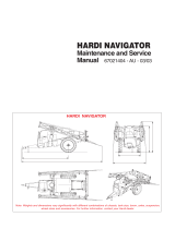
Figure 1: Connecting the
Spray ECU to existing Installations.

Installing the Spray ECU
1.1 INSTALLING THE SPRAY ECU (ALL MODELS)
Step
1:
Installing
the
Spray
ECU
30S
1. Mount the Spray ECU (Electronic Control Unit) shown in Figure 2 in a suitable position
inside the cab ensuring that it and its connectors cannot be accidentally damaged by
moving objects, the Spray ECU can be mounted in any orientation. Figure 4 shows the
in-cabin assembly showing Spray ECU, Switch Box, Power Comms and Tractor Harness.
Please refer to the ZYNX Console (X15 or X20) manual for mounting the ZYNX Console.
Page 11
V1.98 21/06/06
NNoottee::
DDIISSCCOONNNNEECCTT
TTHHEE
VVEEHHIICCLLEE
BBAATTTTEERRYY
bbeeffoorree
pprroocceeeeddiinngg
wwiitthh
aannyy
iinnssttaallllaattiioonn
oorr
sseerrvviicciinngg
ooff
tthhee
SSpprraayy
EECCUU
3300SS
oorr
TTrraaccttoorr
hhaarrnneessss..
BBeeffoorree
ccoommmmeenncciinngg
aannyy
i
innssttaallllaattiioonn
oorr
sseerrvviicciinngg
ooff
tthhee
SSpprraayyeerr
HHaarrnneessss
oorr
VVaallvvee
HHaarrnneessss,,
mmaakkee
ssuurree
tth
hee
TTrraaccttoorr
HHaarrnneessss
iiss
ddiissccoonnnneecctteedd
ffrroomm
tthhee
SSpprraayyeerr
hhaarrnneessss..
DDAAMMAAGGEE
WWIILLLL
OOCCCCUURR
iiff
aannyy
eexxtteerrnnaall
ppoowweerr
iiss
aapppplliieedd
ttoo
tthhee
SSeeccttiioonn
DDrriivvee
OOuuttppuuttss
oonn
tthhee
SSpprraayy
EECCUU..
AALLWWAAYYSS
DDIISSCCOONNNNEECCTT
TTHHEE
VVEEHHIICCLLEE
BBAATTTTEERRYY
bbeeffoorree
pprroocceeeeddiinngg
wwiitthh
aannyy
wweellddiinngg,,
j
juummpp
ssttaarrttiinngg
oorr
cchhaarrggiinngg
oonn
tthhee
vveehhiiccllee
oorr
sspprraayyeerr..
2. Install the Power/Comms Harness. Route the red and black wires to a 12 volt battery.
DO NOT CONNECT TO BATTERY, UNTIL INSTALLATION IS COMPLETE.
Use the cable ties provided to secure the Power/Comms Harness away from hot and
moving parts and to avoid chaffing and wear.
3. Plug the ‘Switched Power’ connector that is located on the Power/Comms Harness, into
the ‘Switched Power’ connector on the ZYNX Power Cable. If this connection is already
utilized, connect it via the A1953 Power Splitter Harness. This connection ensures that
the Spray ECU is only powered up when the ZYNX Console is switched ON.
4. One end of the Power/Comms Harness has 'DB 9-Pin' Comms Cable connection.
Connect this cable to the next available COM Port at the back of the ZYNX Console.
5. Connect the other end of the Power/Comms Harness to the 16-pin connector marked
‘POWER/COMMS’ on the Spray ECU.
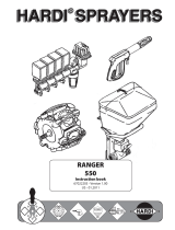
Figure 2: Spray ECU 30S
Figure 3: Sprayer Switchbox

Installing the Spray ECU
6. Connect the Sprayer Switchbox, shown in Figure 3, to the '9-pin connector marked
SWITCHBOX on the Spray ECU. Then mount the Sprayer Switchbox using the double-
sided tape supplied or other suitable means. Mount the Sprayer Switchbox in a
position which is easily accessible while spraying.
Note: The Sprayer Switchbox can be used so, one switch, switches one boom section
ON and OFF. If the sprayer has more than six boom sections then the ZYNX Sprayer
software can be setup so that one section switch, switches more than one boom section
ON and OFF. The operator can custom map the boom sections.
See Section 17.10 for details of the functions of the Sprayer switchbox.
7. For reference or troubleshooting at the back of this manual Section 21.7 shows the
pin out tables for each of the Spray ECU 30S Connector’s.
Page 12
V1.98 21/06/06

Installation of Spray ECU 30S KEE Sprayer Kits
11..22 IInnssttaallllaattiioonn
ooff
SSpprraayy
EECCUU
3300SS
KKEEEE
SSpprraayyeerr
KKiittss
All KEE Sprayer kits come with their installation guide which is specific to each kit,
please use the specific installation guide which come with your KEE Sprayer kit. This
section is a general guide for an installation of all KEE Spray ECU 30S Sprayer kits.
This installation guide will take the installer through the following steps:
1.2.1 Installing the Tractor Harness
1.2.2 Installing the Sprayer Harness
1.2.3 Installing the Valve Harness
1.2.1 Installing
the
Tractor
Harness
1. Connect the Tractor Harness to the 37-Pin connector marked CONNECTOR 1, on the
Spray ECU. Figure 4 shows the in-cabin assembly showing Spray ECU, Power/Comms
Harness, Switchbox and Tractor Harness.
2. Run the Tractor Harness from the Spray ECU to the drawbar or the back of the vehicle.
Ensure that the Tractor Harness is tied away from moving, hot or sharp objects. Do not
cut or splice the Tractor Harness, all excess cable should be strapped away to avoid
vibration and wear.
3. If the Tractor Harness has ‘2’ 37 pin connectors, then connect the ‘37’ pin connector
(male pins) marked ‘CONNECTOR 1’ to the plug marked ‘CONNECTOR 1’ on the Spray
ECU. Then connect the ‘37’ pin connector (female pins) marked ‘CONNECTOR 2’ to the
plug marked ‘CONNECTOR 2’ on the Spray ECU.
Note: As a general rule the ‘CONNECTOR 2’ plug is only required if:
a) The sprayer has more than 10 boom sections.
b) The sprayer has more than ‘2’ tanks.
c) The Spray ECU is connecting to external switches which control the boom
sections (boom sensing); for example boom section switches on a ‘T Bar’ or
‘Joy Stick’ or other ‘third party’ section switches.
4. Normally ‘CONNECTOR 3’ (16 pin) is only required if the sprayer requires extra
pressure inputs, tank level sensors and extra encoder inputs. See Wiring Connections
table for the Spray ECU 30S (A2643) controller for wiring pin-outs;( See Section 21.7).
5. The Tractor Harness has a 3-pin Weather Pack connector labeled Ground Speed, either
an A328 Shaft/Speed Sensor Kit or A449 Radar Sensor Interface Harness (not included
in this kit) can be connected to this connector. Typically the Radar Sensor Interface
Harness would be connected to the Tractor Harness Ground Speed connector. Only
one (1) speed connector must be used at any one time. Refer to 1.2.2 for installing
the Shaft/Speed Sensor Kit or Radar Sensor Interface Harness.
Page 13
V1.98 21/06/06

General System Layout for Spray ECU 30S KEE Controller Kits
Page 14
V1.98 21/06/06
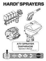
Connects to Sprayer Harness
Figure 4: General Incab assembly

General System Layout for Spray ECU 30S KEE Controller Kits
Page 15
V1.98 21/06/06
Tractor Harness
Dump Valve
Sprayer Loom
Figure 5: General Sprayer and Valve harness assembly

Installation of Spray ECU 30S KEE Sprayer Kits
1.2.2 Installing
the
Sprayer
Harness
1. The Sprayer Harness connects to the Tractor Harness at the back of the tractor or
vehicle via the connector and continues across the sprayer's chassis to the valve
set. Figure 5 shows the Sprayer Harness and Valve Harness Assembly.
2. Do not cut or splice the Sprayer Harness. Excess cable should be strapped away to
avoid vibration and wear.The typical Sprayer Harness has 5 connectors, they are
labeled as follows:
GGrroouunndd
SSppeeeedd
- connects to the Shaft/Speed Sensor Kit which is supplied as part of this kit.
FFllooww
MMeetteerr
11
- connects to a flow meter (not supplied).
PPrreessssuurree
SSeennssoorr
11-
connects to the Pressure Sensor which is supplied as part of this kit.
RREEGG
VVaallvvee
11-
connects to a regulator valve (not supplied).
VVaallvvee
HHaarrnneessss-
connects to the Valve Harness which is supplied as part of this kit.
Note: The Sprayer Harness may have other connectors, refer to the Sprayer Installation kit that
came with your sprayer kit for more information. The Dump Valve connector may be located
on the Sprayer Harness. If the Valve Harness has an ‘Arag Interface box’ incorporated into the
Valve Harness, then the ‘Dump Valve’ connector will be located on the Valve Harness.
Troubleshooting Tip: For testing purposes on all 3-pin sensor connectors (Shaft/Speed Sensor
and Flow Meter) the voltage on each pin should be as follows: Pin A: +5 VDC Signal, Pin B:
Ground, Pin C: +12VDC Sensor Power. Refer to Figure 6 below:
Connecting
to
a
Speed
Sensor
This installation is used if connecting an A328 Shaft/Speed Sensor Kit (for ground speed) or
A449 Radar Sensor Interface Harness (not supplied) to the Ground Speed connector on either
the Tractor Harness or Sprayer Harness.
CCoonnnneecctt
ttoo
oonnllyy
oonnee
((11))
ooff
tthhee
GGrroouunndd
SSppeeeedd
ccoonnnneeccttoorrss..
Select one of the following:
a) Installing the Shaft/Speed Sensor Kit to an un-driven wheel on either the Tractor
Harness or Sprayer Harness;
b) Installing the Shaft/Speed Sensor Kit to the Tail Shaft of a vehicle on either the Tractor
Harness or Sprayer Harness;
c) Use and existing radar speed sensor for ground speed.
Installation
of
the
Shaft/Speed
Sensor
kit
to
an
un-ddriven
wheel
for
Ground
Speed
1. The Shaft/Speed Sensor and Wheel Stud Magnets can be fitted to any un-driven ground
wheel, for example: front wheel of tractor or wheel on trailing sprayer. The magnet
activates the sensor as the wheel magnets sweep past. Refer to Figure 8.
Note: Use of a driven wheel for ground speed may be subject to "wheel slip" and may
not always reflect true ground speed.
Page 16
V1.98 21/06/06
Figure 6 : 3-Pin Weather Pack Sensor

Installation of Spray ECU 30S KEE Sprayer Kits
2. Glue the magnets to the wheel studs with the side marked with a cross (+) facing the
Shaft/Speed Sensor. Use any silicone or epoxy type adhesive allowing adequate time
to set. Ensure that the magnets are spaced equally around the wheel to ensure
accurate speed update. To ensure adequate speed update place magnets onto ALL of
the available wheel studs. A Wheel Calibration Factor of no greater than 0.6m (24
inches) is required. Please note that the Hose Clamp and Magnetic Block are not used
in this case.
3. The Shaft/Speed Sensor must be rigidly mounted to an existing structure on the axle,
ideally in a protected position to face the magnet. The Mounting Bracket Assemblies
(slotted brackets and angle brackets with hose clamps) provided can be used to
construct a mounting bracket refer Figure 7 or you may fabricate your own mounting
bracket to suit the sprayer chassis.
IImmppoorrttaanntt::
TThheerree
mmuusstt
bbee
NNOO
mmoovveemmeenntt
ooff
tthhee
sseennssoorr
rreellaattiivvee
ttoo
tthhee
mmaaggnne
ett..
4. The Shaft/Speed Sensor to Wheel Stud Magnet distance needs to be 2 to 3 mm (1/16 to
1/8 inch). The Shaft/Speed Sensor must be mounted so that the Wheel Stud Magnets
pass the sensor evenly and squarely.
5. Protect the Shaft/Speed Sensor and wiring from damage if necessary by welding or
bolting a suitable plate over the. Damage to the front face of the Shaft/Speed Sensor
will stop the speed readout and prevent the controller from working.
6. If the Shaft/Speed Sensor is mounted on a steered wheel, then make sure the sensor
moves with the steering mechanism, to maintain constant clearance between the
magnets and the sensor when the wheel is turning from lock to lock.
7. Use the 3-pin Weather Pack Extension provided if required, connecting the Shaft/Speed
Sensor to either the Ground Speed connector on the Tractor Harness or Sprayer
Harness.
Page 17
V1.98 21/06/06
Figure 7 : Shaft/Sensor with Mounting Bracket
Figure 8 : Shaft/Speed Sensor on an
un-driven wheel installation

Installation of Spray ECU 30S KEE Sprayer Kits
Installation
of
a
Shaft/Speed
Sensor
kit
to
a
tail
shaft
1. On a tray mounted sprayer the Shaft/Speed Sensor Kit can used to read from the
vehicle tail-shaft. Refer to Figure 9. Using the Hose Clamp or other suitable means
securely mount the Magnet Block on the flange between the transmission housing and
the tail shaft. Note: Do not attach the Magnet Block directly to the tail shaft as its
position changes through its rotation. The Wheel Stud Magnets are not used in this
case.
2. Using an existing bolt on the transmission housing and the supplied Mounting Brackets
or other suitable means, securely mount the Shaft/Speed Sensor so it squarely faces the
Magnet Block with a clearance of 2 to 3mm (1/16 to 1/8 inch).
3. Ensure that the Shaft/Speed Sensor is firmly attached and protected so that it cannot
be damaged by wire or stones. If necessary cover the Shaft/Speed Sensor with a plate.
4. Use the 3-pin Weather Pack Extension provided if required, connecting the Shaft/Speed
Sensor to the Ground Speed connector on the Tractor Harness or Sprayer Harness.
Using
an
existing
radar
speed
sensor
for
ground
speed
1. An optional Radar Sensor Interface Harness (A449 - not provided as part of this kit but
may be ordered separately) allows direct connection to any existing radar speed sensor
on the tractor.
2. Connect the Radar Sensor Interface Harness to the Ground Speed connector on the
Sprayer Harness or Tractor Harness then connect this wire to the signal wire from the
radar sensor (not provided) to enable the Spray ECU to read the speed. Note: Check
the radar sensor manufacturer's manual before attempting connection. Use the
Extension Harness provided if required connecting the radar sensor to the Ground
Speed connector on either the Sprayer Harness or Tractor Harness.
Page 18
V1.98 21/06/06
Figure 9 : Shaft/Sensor Sensor installation a tail shaft

Installation of Spray ECU 30S KEE Sprayer Kits
Connecting
to
Flow
Meter
1. The flow meter (not supplied) is installed between the regulator valve and the section
valves. The flow meter will be installed so that it measures ONLY the quantity of liquid
being delivered to the spray line.
Note: There must be no return line to tank or pump after the flow meter.
2. Connect the flow meter 3-pin connector to the 3-pin connector marked Flow Meter 1
on the Sprayer Harness.
Note: The flow meter may require a connector change to attach to the 3-pin connector
marked Flow Meter 1 on the Sprayer Harness. Refer to the flow meter manufacturer's
specifications for correct pin allocation. Care should be taken when replacing these
connectors not to damage the Sprayer Harness or flow meter and connectors should
be fully circuit tested prior to installation.
3. Most flow meters have a label on the meter body that shows the flow meter
Calibration Factor in pulses/volume. For example: '645 ppl' (pulses per litre) or 2441
ppg (pulses per gallon). This value is the Calibration Factor and will be required to be
entered into the sprayer software setup. This means the flow meter sends 645 pulses
to the Spray ECU for every litre (or 2441 pulses for every gallon) of liquid that passes
through the flow meter.
4. For connection to a Raven flow meter: The value marked on the label represents
pulses/10 units of liquid. Divide this number by 10 for the correct value to enter as the
Calibration Factor into the Sprayer Software Setup.
Connecting
to
the
Regulator
Valve
1. The regulator valve (not supplied) is a motorized flow control valve used to maintain
the product flow to the section valves. It will be situated between the pump and the
flow meter.
2. All bypass or agitation return lines that return to tank must be taken before the
regulating valve, so there is no return path after the regulating valve and the flow
sensor.
3. Using the Regulator Valve Adaptor Harness (A802) connect the regulator valve's 2-pin
connector to the 2-pin connector marked REG Valve 1 on the Sprayer Harness.
Note: The regulator valve may require a connector change to attach to the 2-pin
connector marked REG Valve 1 on the Sprayer Harness. Refer to the regulator valve
manufacturer's specifications for correct pin allocation. Care should be taken when
replacing these connectors not to damage the Sprayer Harness or regulator valve and
connectors should be fully circuit tested prior to installation.
4. When you test the sprayer with water you may find that the regulator valve works in
the opposite direction than is required. For example the pressure increases when it
should decrease. You can set the "Reverse Valve Direction" in the Sprayer Setup
software to remedy this.
Page 19
V1.98 21/06/06

Major Topic Heading
Installation of Spray ECU 30S KEE Sprayer Kits
Pressure
Sensor
installation
and
connection
1. Mount the Pressure Sensor (A092) either upright or horizontal and support the brass
gauge saver. To properly measure Spray Line operating pressure the Pressure Sensor
must be positioned between the flow meter and the section valves. The supplied
Pressure Sensor is a 5 Bar (72 psi) pressure sensor.
2. Connect the Pressure Adaptor Harness (H1125) to the connector labeled Pressure Sensor 1
on the Sprayer Harness.
3. Undo the two (2) nuts on top of the Pressure Sensor.
4. Place the two ring terminals on the Pressure Adaptor Harness onto the terminals on the
Pressure Sensor. It doesn't matter which way around the terminals are attached to the
Pressure Sensor.
5. Once the ring terminals are placed on the Pressure Sensor terminals replace the two (2)
nuts and tighten the nuts securely.
1.2.3 Installing
the
Valve
Harness
1. The Valve Harness continues from the connector on the Sprayer Harness and connects to
the Section and Dump Valves on the Sprayer.
2. The Valve Harness normally contains connectors for the section valves; either they are; ‘3
Wire section valves’, ‘2 Wire Section Valves’ or ‘solenoid valves’.
See below for an
explanation of the different types of section valves..
Note: If the Valve Harness has an Arag Interface box incorporated into the harness, then
the Dump Valve plug will be on the Valve Harness.
5. The typical Valve Harness has the following connectors, they are labeled as follows:
DDuummpp
11-
connects to the Dump Valve.
SSeeccttiioonn
XX-
connects to the Section Valves. ‘X’ represents the section number.
SSpprraayyeerr
HHaarrnneessss-
connects to the Sprayer Harness.
3. There are different Valve Harness depending on which type of section valves on fitted on
the sprayer.
Note: If the Valve looms need to be re-terminated because the connectors are different to
the section valves being connected to, then make sure the ‘Sprayer Harness’ is
disconnected from the ‘Tractor Harness’. Otherwise damage to the Spray ECU
wwiillll
occur if
the wires are shorted out during the installation.
4. Secure the Valve Harness away from moving, hot or sharp objects to avoid chaffing and
wear, using the cable ties provided.
6. Connect the Valve Harness to the Sprayer Harness.
Page 20
V1.98 21/06/06
/