Page is loading ...

EVRARD
GROUPE
HARDI
ALPHA 2500
ALPHA 2500
Reference : 677824
Edition : 01/02
OPERATING and
MAINTENANCE Manual

AALPHA
SUMMARY
677824
02/00
1- DECLARATION OF CONFORMITY FOR EEC --------------------------------------------------
1-1 USING THE SELF-PROPELLED ----------------------------------------------------------
2-2 RECOMMANDATIONS GENERALES ---------------------------------------------------
2-3 ROAD DRIVING --------------------------------------------------------------------------------
2-4 PLANT PROTECTION PRODUCTS ------------------------------------------------------
2-5 CLEANING THE SPRAYER -----------------------------------------------------------------
2- DESCRIPTION OF SPRAYER ---------------------------------------------------------------
2-1 MAIN EQUIPMENT IDENTIFICATION ---------------------------------------------------
2-2 SAFETY PRECAUTIONS --------------------------------------------------------------------
2-3 IDENTIFICATION ------------------------------------------------------------------------------
2-4 INSTRUMENT PANEL DESCRIPTION --------------------------------------------------
2-4-1 CAB CONSOLE ------------------------------------------------------------------------
2-4-2 CONSOLE ------------------------------------------------------------------------------
2-4-3 CAB ACCESSOIRIES -----------------------------------------------------------------
2-5 DRIVER’S COMFORT -----------------------------------------------------------------------
2-5-1 SIEAT -----------------------------------------------------------------------------------
2-5-2 HEATING -------------------------------------------------------------------------------
2-5-3 AIR CONDITIONING -------------------------------------------------------------------
2-6 ENGINE -----------------------------------------------------------------------------------------
2-6-1 ENGINE ACCESS -----------------------------------------------------------------------
2-6-2 STARTIND THE ENGINE ----------------------------------------------------------------
2-6-3 ENGINE ACCELERATOR ---------------------------------------------------------------
2-6-4 STOPPING THE ENGIN-----------------------------------------------------------------
2-7 ADVANCE CONTROL ------------------------------------------------------------------------
2-7-1 DRIVER’S CONTROL LEVER ----------------------------------------------------------
2-7-2 BRAKE EGINE --------------------------------------------------------------------------
2-7-3 PARKING BRAKE -----------------------------------------------------------------------
2-7-4 SPEED SELECTOR --------------------------------------------------------------------
FAST Speed
---------------------------------------------------------------------------
SlLOW Speed --------------------------------------------------------------------------
‘’INTERMEDIATE’’ Speed ---------------------------------------------------------------
2-8 WHEEL STEERING ---------------------------------------------------------------------------
2-8-1 DESCRIPTION --------------------------------------------------------------------------
2-8-2 TWO WHEEL STEERING
---------------------------------------------------------------
2-8-3 FOUR WHEEL STEERING ------------------------------------------------------------
2-8-4 TWO WHEEL IN ‘’CRAB’’ FORMATION ------------------------------------------------
2-9 SPRAY PUMP ----------------------------------------------------------------------------------
2-10 BOOM FUNCTIONS -------------------------------------------------------------------------
2-10-1 SAFETY
-------------------------------------------------------------------------------
2-10-2 JOYSTICK DESCRIPTION ------------------------------------------------------------
2-10-3 ‘’LA’’ ALUMINIUM BOOM --------------------------------------------------------------
2-10-4 ‘’GVA’’ ALUMINIUM BOOM WITH VARIABLE GEOMETRY ------------------------
2-11 SPRAY ------------------------------------------------------------------------------------------
2-11-1 SPRAY SECTIONS SWITCHES
-----------------------------------------------------
2-12-2 FOAM MARKER ------------------------------------------------------------------------
SUMMARY
I
1-1
1-2
1-3
1-4
1-4
1-5
2-1
2-1
2-2
2-3
2-4
2-4
2-5
2-8
2-6
2-6
2-7
2-7
2-8
2-8
2-8
2-9
2-9
2-10
2-10
2-10
2-11
2-11
2-12
2-12
2-12
2-13
2-13
2-13
2-14
2-15
2-16
2-16
2-16
2-17
2-18
2-19
2-20
2-20
2-20

ALPHA
II
SUMMARY
677824
02/2000
3- PREPARATION -------------------------------------------------------------------------------------------
3-1 ELECTRIC CIRCUIT -------------------------------------------------------------------------
3-2 DIESEL TANK ----------------------------------------------------------------------------------
3-3 HYDRAULIC OIL RESERVOIR ------------------------------------------------------------
3-4 PUMP STEP-UP GEAR CASE ------------------------------------------------------------
3-5 ENGINE ------------------------------------------------------------------------------------------
3-6 TYRES --------------------------------------------------------------------------------------------
3-6-1 PRESSURE ------------------------------------------------------------------------------
3-6-2 BOLTS TIGHTING ----------------------------------------------------------------------
3-6-3 STRAW DIVIDERS ---------------------------------------------------------------------
3-7 SPRAY --------------------------------------------------------------------------------------------
3-7-1 FITTING THE NOZZLES ---------------------------------------------------------------
3-7-2 FILTERS ---------------------------------------------------------------------------------
Suction filter ----------------------------------------------------------------------------
delivery filter ----------------------------------------------------------------------------
In-line filters -----------------------------------------------------------------------------
3-7-3 DRAINING PLUGS ----------------------------------------------------------------------
Boom manifold -------------------------------------------------------------------------
Mix/ Admixturer -------------------------------------------------------------------------
Centrifugal pump ------------------------------------------------------------------------
Diaphrams pump ------------------------------------------------------------------------
3-7-4 DRAIN VALVE AND FLOATING GAUGE -----------------------------------------------
3-7-5 CLEAN CUT-OFF (OPTION) ------------------------------------------------------------
4 - SPRAYING ------------------------------------------------------------------------------------------------
4-1 PRINCIPE OF CIRCULATION -------------------------------------------------------------
4-1-1 NORMAL CIRCULATION ---------------------------------------------------------------
4-1-2 SEMI-CONTINUOUS CIRCULATION -------------------------------------------------
4-1-3 CONTINUOUS CIRCULATION --------------------------------------------------------
4-2 DETAILS FOR SPRAYING STAGES -----------------------------------------------------
4-2-1 PICTOGRAMS ---------------------------------------------------------------------------
4-2-2 NORMAL CIRCULATION --------------------------------------------------------------
4-2-3 SEMI-CONTINUOUS CIRCULATION -------------------------------------------------
4-2-3 SEMI-CONTINUOUS CIRCULATION -------------------------------------------------
4-3 SPRAYING CIRCUIT OPERATING ------------------------------------------------------
4-3-1 FILLING THE HAND WASHING TANK AND THE RINSING TANK -------------------
Hand washing ---------------------------------------------------------------------------
Rinsing tank -----------------------------------------------------------------------------
4-3-2 PRIMING THE PUMP -------------------------------------------------------------------
4-3-3 FILLING THE MAIN TANK -------------------------------------------------------------
Filling by external suction ----------------------------------------------------------------
Filling by means of the main tank --------------------------------------------------------
4-3-4 ADDING THE PRODUCTS -------------------------------------------------------------
4-3-5 AGITATION OF MAIN TANK ------------------------------------------------------------
4-3-6 SPRAYING ------------------------------------------------------------------------------
In NORMAL Circulation --------------------------------------------------------------
In SEMI-CONTINUOUS or CONTINUOUS Circulation
----------------------------
Radar unit adjustment ----------------------------------------------------------------
4-3-7 SPRAYING WITH AGITATION --------------------------------------------------------
4-3-8 SPRAYING WITHOUT AGITATION ----------------------------------------------------
3-1
3-1
3-1
3-2
3-2
3-3
3-3
3-3
3-3
3-3
3-4
3-4
3-4
3-4
3-5
3-5
3-5
3-5
3-5
3-5
3-5
3-6
3-6
4-1
4-1
4-1
4-2
4-2
4-4
4-4
4-5
4-6
4-7
4-9
4-9
4-9
4-9
4-9
4-11
4-10
4-11
4-11
4-12
4-13
4-13
4-13
4-13
4-13
4-14

ALPHA
III
SUMMARY
677824
04/01
4-3-9 LOW VOLUME SPRAYING -------------------------------------------------------------
4-3-10 RINSING THE BOOM ------------------------------------------------------------------
4-3-11 TRANSFER -----------------------------------------------------------------------------
4-3-12 EMPTYING THE MAIN TANK ----------------------------------------------------------
4-3-13 MAIN TANK RINSING ------------------------------------------------------------------
4-3-14 EMPTYING THE RINSING TANK ------------------------------------------------------
4-3-15 EMPTYING THE BOOM PIPING (OPTION CLEAN CUT-OFF) ----------------------
5 - CARE AND MAINTENANCE -------------------------------------------------------------------------
5-1 TABLE OF LUBRICANTS -------------------------------------------------------------------
5-2 MAINTENANCE DURING THE RUNNING-IN-PERIOD -----------------------------
5-3 PERIODIC AND PREVENTIVE MAINTENANCE --------------------------------------
5-3-1 ENGINE MAINTENANCE ----------------------------------------------------------------
Coolant level -----------------------------------------------------------------------------
Heat exchanger cleaning -----------------------------------------------------------------
Air filter-----------------------------------------------------------------------------------
Changing Engine oil ---------------------------------------------------------------------
Changing fuel filter and draining fuel prefilter ---------------------------------------------
Fuel circuit venting -----------------------------------------------------------------------
Fuel prefilter -----------------------------------------------------------------------------
Fuel tank --------------------------------------------------------------------------------
Safety cartridge --------------------------------------------------------------------------
Draining cooling system -----------------------------------------------------------------
5-3-2 EVERY HOURS --------------------------------------------------------------------------
Spray filters ------------------------------------------------------------------------------
5-3-3 EVERY 10 HOURS ----------------------------------------------------------------------
Hydraulic oil level ------------------------------------------------------------------------
Air conditioning condenser ---------------------------------------------------------------
Air compressed reservoir ----------------------------------------------------------------
5-3-4 EVERY 50 HOURS ---------------------------------------------------------------------
Diaphrams pump H463 ------------------------------------------------------------------
Wheels ----------------------------------------------------------------------------------
Chassis and boom -----------------------------------------------------------------------
DG Regulating valve ---------------------------------------------------------------------
TVI Remote valve ------------------------------------------------------------------------
5-3-5 EVERY 100 HOURS --------------------------------------------------------------------
Antifreeze unit ---------------------------------------------------------------------------
Filter-Lubrificator unit ---------------------------------------------------------------------
5-3-5 EVERY 250 HOURS ---------------------------------------------------------------------
Pump step-up gear case oil level ---------------------------------------------------------
Hydraulic filters --------------------------------------------------------------------------
Carbon cab filters ------------------------------------------------------------------------
HELIFLUX Flowmeter -------------------------------------------------------------------
Four-way nozzles and ‘’Clean cut-off’’ ----------------------------------------------------
5-3-7 EVERY 500 HOURS ---------------------------------------------------------------------
Air conditioning --------------------------------------------------------------------------
5-3-6 EVERY 1000 HOURS OR ANNUAL ----------------------------------------------------
Nitrogen accumulator---------------------------------------------------------------------
Draining the step-up gear case -----------------------------------------------------------
Valves and diaphrams --------------------------------------------------------------------
Battery case -----------------------------------------------------------------------------
Cab --------------------------------------------------------------------------------------
4-14
4-15
4-16
4-16
4-17
4-17
4-18
5-1
5-1
5-2
5-3
5-3
5-3
5-3
5-4
5-4
5-4
5-5
5-5
5-5
5-6
5-6
5-7
5-7
5-7
5-7
5-7
5-8
5-8
5-8
5-8
5-9
5-10
5-10
5-11
5-11
5-11
5-11
5-11
5-12
5-12
5-13
5-13
5-14
5-14
5-14
5-14
5-15
5-15
5-15
5-16

ALPHA
IV
SUMMARY
677824
02/2000
6-GARAGING ----------------------------------------------------------------------------------------------------
6-1 SPRAYERr -----------------------------------------------------------------------------------------
6-2 BOOM PIPING ------------------------------------------------------------------------------------
6-3 DG4 REGULATING VALVE --------------------------------------------------------------------
6-4 ‘’HELIFLUX’’ FLOWMETER----------------------------------------------------------------------
6-5 MIXING UNIT FOR PRODUCTS --------------------------------------------------------------
6-6 BOOM MANIFOLD -------------------------------------------------------------------------------
6-7 MANUAL VALVES ---------------------------------------------------------------------------------
6-8 DIESEL TANK --------------------------------------------------------------------------------------
7 - FAULTS IN OPERATION ---------------------------------------------------------------------------------
7-1 ELECTRIC CIRCUIT -----------------------------------------------------------------------------
7-1-1 FUSES AND RELAY ------------------------------------------------------------------------
7-1-2 PRINCIPLE WIRING DIAGRAM -----------------------------------------------------------
7-1-3 AIR CONDITIONING WIRING DIAGRAM -------------------------------------------------
7-1-4 ENGINE -------------------------------------------------------------------------------------
7-1-5 FOUR-WHEELS STEERING ---------------------------------------------------------------
7-2 HYDRAULIC CIRCUITS -----------------------------------------------------------------------
7-2-1 OIL RESERVOIR ALARM ------------------------------------------------------------------
7-2-2 TOWING -------------------------------------------------------------------------------------
ACTION ON WHEEL MOTORS ------------------------------------------------------------
ACTION ON THE ADVANCING HYDROSTATIC PUMP --------------------------------------
7-2-3 BOOM CONTROL DISTRIBUTOR ---------------------------------------------------------
7-2-4 HYDRAULIC CIRCUIT ----------------------------------------------------------------------
7-3 SPRAYING CIRCUIT -----------------------------------------------------------------------------
7-3-1 PUMP DOES NOT PRIME -----------------------------------------------------------------
7-3-2 FOAM FORMS ------------------------------------------------------------------------------
7-3-3 NO ADMIXTURE OF PRODUCTS ---------------------------------------------------------
7-3-4 INCORRECT SPRAYING -------------------------------------------------------------------
7-3-5 NO SPRAYING ------------------------------------------------------------------------------
7-3-6 VOLUME/HA CANNOT BE OBTAINED ----------------------------------------------
7-3-7 REGULOR -----------------------------------------------------------------------------------
Removal of Regulor unit --------------------------------------------------------------------
7-3-8 DG4 REGULATING VALVE -----------------------------------------------------------------
7-3-9 WHEEL SENSOR ---------------------------------------------------------------------------
7-3-10 ‘’HELIFLUX’’ FLOWMETER ---------------------------------------------------------------
7-3-11 PRESSURE GAUGE ----------------------------------------------------------------------
8 - LIST OF MAIN PARTS ------------------------------------------------------------------------------------
9 - TECHNICALS SPECIFICATION ------------------------------------------------------------------------
9-1 ENGINE ----------------------------------------------------------------------------------------------
9-2 TRANSMISSION -----------------------------------------------------------------------------------
9-3 SUSPENSION --------------------------------------------------------------------------------------
9-4 STEERING ------------------------------------------------------------------------------------------
9-5 TRACK -----------------------------------------------------------------------------------------------
9-6 BRAKES ---------------------------------------------------------------------------------------------
9-7 CAB ---------------------------------------------------------------------------------------------------
9-8 TYRES -----------------------------------------------------------------------------------------------
9-9 TANK AND RESERVOIRS ----------------------------------------------------------------------
9-10 ELECTRICAL SYSTEM ------------------------------------------------------------------------
9-11OVERALL DIMENSIONS -----------------------------------------------------------------------
9-12 WEIGH T--------------------------------------------------------------------------------------------
9-13 SPRAYING ----------------------------------------------------------------------------------------
6-1
6-1
6-1
6-1
6-2
6-2
6-2
6-2
6-2
7-1
7-1
7-1
7-4
7-5
7-6
7-6
7-7
7-7
7-7
7-7
7-8
7-10
7-11
7-12
7-12
7-12
7-12
7-12
7-13
7-13
7-13
7-14
7-14
7-15
7-15
7-15
8-1
9-1
9-1
9-1
9-1
9-1
9-1
9-1
9-1
9-1
9-1
9-1
9-2
9-2
9-2

AALPHA 2500
1- 2
FOREWORD
677824
01/02
The agricultural sprayer is designed for applying plant protection products and liquid fertilizers to
crops. It must be used only for this purpose, to the exclusion of all others.
Please follow the Highway Code and any regulations in force with regard to road driving.
We strongly recommend that you obtain training in crop protection and handling plant protection
products to ensure crop treatment with total safety for those accompanying you and for the envi-
ronment.
All the following specifications and characteristics are subject to improvements without notice and immediate revision
of this manual.
1-1 USING THE SELF-PROPELLED ALPHA
1-2 DELIVERY REPORT
The delivery report, given when the mobile unit is delivered, must be returned to :
HARDI EVRARD
BP 59
77542 SAVIGNY LE TEMPLE CEDEX
FRANCE
duly completed, dated and signed by the concessionaire and the user, the return of this
document causing the guarantee to start running.We would ask you to read carefully the
guarantee clauses stipulated in the delivery report.

ALPHA 2500
1- 4
FOREWORD
677824
01/02
Chemicals will penetrate gloves, rubber boots etc. after a certain period of contact. This period
will vary from a few hours to several days depending on rubber materials and chemical used. Be
familiarised with the quality of your protection equipment, and renew them according to the ins-
tructions.
Wash your gloves before taking them off. Do not touch the contaminated outer side of the gloves
with bare hands when taking them off.
If chemicals are splashed over you, remove soaked clothing at once and was with soap and water
instantly. Plant protection chemicals will penetrate the skin, and affect your health. Consult che-
mical label regarding precautions to be taken against poisoning.
Please obtain current information for decontamination methods (e.g. leaching of pesticides).
If you do not know this legislation, refer to the agricultural authorithies (Department of Agriculture)
The sprayer must be cleaned on an uncultivated piece of land.There must be no seepage or run-
ning to watercourses, gutters, wells or springs.The rinsing water must not discharge into to drains
1-6 CLEANING THE SPRAYER
1-5 PLANT PROTECTION PRODUCTS
Safe use of sprayers is dependent on the user, who must take the usual precautions when he is
handling plant protection products and working with machine. It is essential to be aware of the
non-compatibility of various different products used and be careful to read the product maker’s
instructions.The sprayer must be carefully cleaned after each use as chemical residues can
damage the spray circuit.
Decree n° 92-1261 of 03 Décembre 1992.
Observe local legislation regarding chemical residues and mandatory decontamination methods.
If in doubt contact the authorities e.g. Department of Agriculture.
Do not store chemicals near the water. Store chemicals behind locked doors. Do not allow unau-
thorized persons and children to access the chemicals.
1-
5
-
1
CONTAINERS
1-
5
-
2
STORAGE OF THE PRODUCTS
1-
5
-
3
PERSONNAL PROTECTION
1-
5
-
4
PLANT PROTECTION CHEMICAL

AALPHA 2500
DESCRIPTION AND USE
CHAPTER 2- 1
677824
01/02
2- DESCRIPTION OF ALPHA SPRAYER
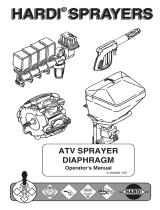
2-1 MAIN EQUIPMENT IDENTIFICATION
Pressure Filter
Mirror
‘MANIFOLD’valves
delivery pump side
‘MANIFOLD’valves
suction pump side
Chemical filler
Rinsing tank
electric spraying
valves TVI
Line filters
Transport Brackets
level gauge
Right boom side
regulating valve DG4
Manual regulating
valve ‘voluréglage’
Transfer connection
calibrated nozzles
(option circulation)
Suction filter
Rear suspension
rotating warning beacon
Identification Plate
(right front)
Hydraulic distributors
connection box
works lights
Left boom side
Ladder
External spraying pump switch
Electric accelerator
Main tank draining valve
Flowmeter

ALPHA 2500
DESCRIPTION AND USE
CHAPTER 2- 2
677824
01/02
!
Danger of falling part
use ladder
!
Danger of user error
!
Hot parts, danger
of burning
DANGER
!
- SHIELD IS
MISSING
- DO NOT
OPERATE
!
DANGER
Do not use if all protection
guards are missing
978436
see operating and mainte-
nance book
2-2 SAFETY PRECAUTIONS
!
978441
!
WARNING
ANTI-FREEZE PROTECTION
Antifreeze of spray circuit during
winter period
978438
!
978442
!
DANGER
!
- SHIELD IS
MISSING
- DO NOT
OPERATE
!
DANGER
978433
978447
!
978439
!
978436
!
!
WARNING
ANTI-FREEZE PROTECTION

ALPHA 2500
DESCRIPTION AND USE
CHAPTER 2- 3
677824
01/02
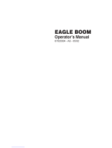
2-3 IDENTIFICATION
The information relating to the identification of the self-propelled Alphat appears on a plate placed
on the right-hand side of the machine. (serial number, type of model, manufacturing date, capaci-
ty of main tank, empty and full weights).
HARDI-EVRARD S.A.
F 62990 BEAURAINVILLE
Marque : EVRARD
N° Série
Année Fabrication
P.V./Kg
Immatriculation
N° Nomenclature
Type
Série
Capacité / L
P.T.C/ Kg
A H 8
ALPHA2500
2000
4 9 5 0 0
5 3 6 5
9 8
8 6 0 0
HARDI EVRARD S.A.
77542 SAVIGNY LE TEMPLE
Direction régionale
de l'industrie et de
la recherche
NORD-PAS DE CALAIS
RÉCEPTIONNÉ LE
A OUTREAU
49500
22-03-96
IDENTIFICATION PLATES
‘’cold’’ marking of serial no
SUNDSTRAND-SAUER
SAUER-SUNDSTRAND
Model Code
Ty p
Ident-Nr
Model No
Armes, Iowa, U.S.A.
Neumünster, W.-Germany
Serial No
Fabr-Nr
MADE IN GERMANY
90 R100 EA 1 N
6 S 3 C6 C 03
HNN 35 35 24
94-2029 687459
N98 22 25551
HYDROSTATIC PUMP PLATE
Type : 000132
N° de série
:
N° homolagation :
088040
28 09 99
CAB PLATE
KHD
DEUTZ
MADE IN GERMANY
Code
Mot- Nr
kW (S)
kW (G)
Mot.-Typ
t/ mn
ISO 1585
BF6M 1012
00292401
2500
2413/00
2,3
98
Code :
Série :
Num :
Indice :
MS08 - 2D - 21 - F08 - 1720 - EJA
009443740K
0 5 7
5 1 8 4 8
60411 VERBERIE
ENGINE PLATE
Maker : EVRARD
Serial number : (5 numbers)
please use the serial number for information and to order parts for your sprayer
Type : general type of the mobile unit AH8
Serial : model ALP2500
Capacity / L : tank nominal capacity 2500
‘’P.V./ Kg’’ : empty weight (*) 5720
P.T.C./ Kg : full weight (*) 8700
(*) approximate values
HYDRAULIC WHEEL PLATE

ALPHA 2500
DESCRIPTION AND USE
CHAPTER 2- 4
677824
01/02
2-4 CONSOLE DESCRIPTION
2-
4
-
1
STEERING COLUMN MOUNTED INSTRUMENT PANEL
20
25
35
30
40
15
10
5
150
50
1/1
0
P
+
-
8
9
10
5
3
2
11
12
13
14
1
4
6
7
+
-
3
Battery charge warning lamp
4
Engine oil pressure warning lamp
P
5
Parking Brake Light
7
Direction indicator warning lamp
8
Position lamp and dipped beam
control lamp
1
Head lamp, main beam
10
Rev. counter and hour meter
2
11
12
Hazard warning light switch
9
14
Multi-function control switch
Horn
120
100
80
40
35
30
25
20
15
10
5
0
Pre Heating light
6
Fuel gauge
Rotating amber warning beacon
switch
Engine temperature gauge
13
Engine temperature and
coolant gauge light

ALPHA 2500
DESCRIPTION AND USE
CHAPTER 2- 5
677824
01/02
VALID
7
8
9
4
5
6
1
2
3
0
,
CE
TEST
VOLUME / HA PROGRAMME
VOLUME / HA
PROGRAMME
VIT.PRESS.
VOLUME / HA
DISTANCE
PARCOURUE
SURFACE
VOLUME
EPANDU
PARCELLES
AUTO
MANUEL
CIRCUL.
CONT.
DEFAUT
HARDI
VOLUME / HA MESURE
VITESSE
PRESSION
VOLUME/HA
GROUPE
REGULOR
TWIN
RPM
+
-
REGU
LOR
S
E
L
E
C
T
I
O
N
N
E
R
A
L
'
A
R
R
E
T
AUTO
MANU
7
8
4
5
31
6
20
19 18 17
23 22
1
Régulor IV console
2
Pump engagement light
3
Steering alignment light front
4
Steering alignment light rear
5
4 Wheel steering mode light
6
4 Wheel steering mode switch
7
Speed selector switch(rotating)
8
Throttle switch
20
Anti-skid switch (optional)
19
Not used
18
Road security switch
17
Ignition switch
21
Foam maker engage and control switch
22
Foam maker increase/decrease switch
23
Twin force fan speed switch
9
Régulor supply switch
10
Liquid pump engagement switch
11
Hydraulic boom folding switches
13
Road security lamp
14
Anti-skid lamp (optional)
15
Joystick forward/reverse
16
Hydraulic and spraying control
12
Isolator warning lamp
2
9 241011121314
16
15
24
Agitation / No agitation switch
OPTIONAL
21
2-
4
-
2
CONSOLE

ALPHA 2500
DESCRIPTION AND USE
CHAPTER 2- 6
677824
01/02
1
16
15
2-
4
-
3
CAB ACCESSOIRIES
2
12
4 53 6
1114 13
810 7
1
Windscreen wiper switch
2
Windscreen washer switch
3
Interior light
4
Map light switch
5
Map reading light switch
6
Map reading light
7
Steering column height adjustment
8
Steering column angle adjustment
9
Heater temperature control
10
Adjustable air vents
11
work lights switch (optional)
13
Front work lights switch
14
2 Speed fan switch
15
Air conditioning fan control 3-speed switch
12
Rear work lights switch
17
2-5 DRIVER’S COMFORT
2-
5
-
1
SEAT
+
-
1
2
4
5
Longitudinal adjustment.
Adjustment according to weight
Front seat cushion angle adjustment
Back seat cushion angle adjustment
back angle adjustment
Arm rest adjustments.
5
1
3
3
4
6
2
9
2
pneumatic seat (Optional)
6
16
3 Speed fan switch, air conditioning
17
Air conditioning air vents
As this is mounted on hydraulic shock absorbers and integrated longituginal suspension, it pro-
tects the driver from shaking which inevitably occurs during driving.The various position adjust-
ments, made by means of identifiable levers, improve comfort.The body-contoured seat and back
cushions are fitted with aerated fabric which is pleasant to the touch and very strong.

ALPHA 2500
DESCRIPTION AND USE
CHAPTER 2- 7
677824
01/02
2-
5
-
2
HEATING
1- Adjust the temperature by means of the thermostat (9)
2- Set the flow of warm air by turning the 2-speed fan switch (14)
3- Stop the air conditioning by turning the switch (15)
4- Open and position the air diffusers (10)
9
14
15
10
10
1416 15 9
2-
5
-
3
AIR CONDITIONING
1- Adjust the temperature by means of the thermostat (16)
2- Set the flow of cold air by turning the 3-position switch (15)
3- Switch off the warm air (14) and set the heater temperature control (9) and set the heater tempera-
ture control to minimum.
Open and position the air diffusers (17)
!
ALWAYS KEEP THE CAB DOOR CLOSED WHEN AIR CONDITIONING IS FUNCTIONING
17
The cab heating is provided by the DEUTZ engine. A ventilation unit with adjustable air vents
located on both sides of the cab provides heating and window de-misting
This includes a unit fitted high up in the cab and a compressor driven by the DEUTZ engine..

ALPHA 2500
DESCRIPTION AND USE
CHAPTER 2- 8
677824
01/02
2-6 ENGINE
2-
6
-
1
ENGINE ACCESS
1
Before starting, the following points must be checked :
- Engine oil level
- Coolant level
- Fuel gauge .
- Hydraulic reservoir oil level
For futher details, see the MAINTENANCE section of this manual and the
engine instruction book
- Place the joystick control lever in the neutral position
A position detector ensures safety when starting
NEUTRAL POSITION
0
1
2
Engine oil pressure
Pre-heating
Battery charge
0
P
+
-
HARDI
GROUPE
TWIN
RPM
+
-
REGU
LOR
S
E
L
E
C
T
I
O
N
N
E
R
A
L
'
A
R
R
E
T
AUTO
MANU
Cut-off battery warning lamp
2-
6
-
2
STARTING THE ENGINE
- Open the bonnet ref 1 by pulling the locking device
- Close the bonnet by pull down it.
- Turn the battery cut-out horizontally; the warning lamp lights up.
- Turn the ignition key to pos. 1, the three-warning lampslight up
and the Cut-off battery goes off

ALPHA 2500
DESCRIPTION AND USE
CHAPTER 2- 9
677824
01/02
2-
6
-
3
ENGINE ACCELERATOR
HARDI
GROUPE
TWIN
RPM
+
-
REGU
LOR
S
E
L
E
C
T
I
O
N
N
E
R
A
L
'
A
R
R
E
T
AUTO
MANU
L
'
A
R
R
E
T
RPM
RPM
+
-
RPM
+
-
RPM
Fig 2-6-1 Fig 2-6-2
- Place the joystick lever to the ‘’neutral’’ position
NEUTRAL POSITION
- Réduce engine speed before stopping, in order to stabilize the engine temperature
40
35
30
25
20
15
10
5
0
0
- Turn the switch key to the left ;The two-warning lamps light up.
The isolator warning lamp light up, as soon as the switch key is on
position 0
0
S
E
L
E
C
T
I
O
N
N
E
R
A
L
'
A
R
R
E
T
- Turn the selector to position parking brake ‘’P ‘’
The two parking brake warning lamps light up.
P
+
-
P
2-
6
-
4
STOPPING THE ENGINE
WARNING
IMMEDIATLY IF THE ENGINE OIL PRESSURE WARNING LAMP STAYS ON, STOP THE ENGI-
!
- Turn the key to position 2 as soon as the pre-heating warning lamp go off
- Release the ignition key as soon as the engine is running, then the engine oil pressure warning
lamps and the battery charge warning lamp go off. go off.
The engine accelerator is provided with an electric control switch on cab panel.

ALPHA 2500
DESCRIPTION AND USE
CHAPTER 2- 10
677824
01/02
HARDI
GROUPE
TWIN
RPM
+
-
REGU
LOR
S
E
L
E
C
T
I
O
N
N
E
R
A
L
'
A
R
R
E
T
AUTO
MANU
WARNING
The hydrostatic transmission calls for high engine speed, giving the main hydraulic pump its
maximum drive and braking performance. For this purpose :
adjust the accelerator lever progressively to an engine speed of a minimum of 1800 to 2000
r.p.m. before moving off.
!
2-
7
-
2
BRAKE ENGINE
2-7 ADVANCE CONTROL
2-
7
-
1
DRIVER’S CONTROL LEVER
0
FORWARD
NEUTRAL
POSITION
- Moving the self-propelled forward by tilting the control lever forward
- Moving the self-propelled reverse by tilting the control lever back
- Braking and stopping the self-proppeled in the ‘’neutral position’’ is carried out by indexing the
lever half-away along its travel.
- Turn the battery cut-out control vertically to prevent battery discharge during a lengthly stoppage.
The Cut-off battery warning lamp go off
REVERSE
FORWARD
NEUTRAL
POSITION
REVERSE

ALPHA 2500
DESCRIPTION AND USE
CHAPTER 2- 11
677824
01/02
Move the advance lever gently, as the hydraulic
brake is very effective)
0
NEUTRAL
POSITION
VALID
7
8
9
4
5
6
1
2
3
0
,
CE
TEST
E
LUME / HA
PROGRAMME
VIT.PRESS.
VOLUME / HA
DISTANCE
PARCOURUE
SURFACE
VOLUME
EPANDU
PARCELLES
AUTO
MANUEL
CIRCUL.
CONT.
DEFAUT
HARDI
VOLUME / HA MESURE
ESSE
PRESSION
VOLUME/HA
GROUPE OUPE
REGULOR
TWIN
RPM
+
-
REGU
LOR
S
E
L
E
C
T
I
O
N
N
E
R
A
L
'
A
R
R
E
T
AUTO
MANU
WARNING
FOR YOUR SAFETY, NEVER ACTIVATE THE PARKING BRAKE WHEN THE
SELF-PROPELLED IS MOVING !
!
S
E
L
E
C
T
I
O
N
N
E
R
A
L
'
A
R
R
E
T
P
S
E
L
E
C
T
I
O
N
N
E
R
A
L
'
A
R
R
E
T
P
ENGAGED
DISENGAGE
2-
7
-
3
PARKING BRAKE
P
P

ALPHA 2500
DESCRIPTION AND USE
CHAPTER 2- 12
677824
01/02
Used for road transport where high speeds are necessary.
Speed range : 0 .. 25 km/h
S
E
L
E
C
T
I
O
N
N
E
R
A
L
'
A
R
R
E
T
Used for field where full traction are necessary.
Speed range : 0 .. 12.5 km/h..
Used generally for spray in the field when driving uphill in slippery
condition where change in weight distribution will cause spinning front
wheels
Speed range : 0 .. 18 km/h
Used generally for spray in the field when driving downhill in slippery
condition where change in weight distribution will cause spinning rear
wheels.
Speed range : 0 .. 18 km/h.
S
E
L
E
C
T
I
O
N
N
E
R
A
L
'
A
R
R
E
T
S
E
L
E
C
T
I
O
N
N
E
R
A
L
'
A
R
R
E
T
S
E
L
E
C
T
I
O
N
N
E
R
A
L
'
A
R
R
E
T
FAST Speed
Slow SPEED
’’ INTERMEDIATE’’ Speed
2-
7
-
4
SPEED SELECTOR
VALID
7
8
9
4
5
6
1
2
3
0
,
CE
TEST
VOLUME / HA PROGRAMME
VOLUME / HA
PROGRAMME
VIT.PRESS.
VOLUME / HA
DISTANCE
PARCOURUE
SURFACE
VOLUME
EPANDU
PARCELLES
AUTO
MANUEL
CIRCUL.
CONT.
DEFAUT
HARDI
VOLUME / HA MESURE
VITESSE
PRESSION
VOLUME/HA
GROUPE
REGULOR
TWIN
RPM
+
-
REGU
LOR
S
E
L
E
C
T
I
O
N
N
E
R
A
L
'
A
R
R
E
T
AUTO
MANU
S
E
L
E
C
T
I
O
N
N
E
R
A
L
'
A
R
R
E
T
FRONT Displacements (1/1)
REAR Displacements (1/2)
FRONT Displacements (1/2)
REAR Displacements (1/1)
FRONT Displacements (1/1)
REAR Displacements (1/1)
FRONT Displacements (1/2)
REAR Displacements (1/2)
1/1 : FULL Displacement - Fields - FULL Torque
1/2 : HALF Displacement - Road transport - LESS Torque

ALPHA 2500
DESCRIPTION AND USE
CHAPTER 2- 13
677824
01/02
2-8 WHEEL STEERING
2-
8
-
2
TWO WHEEL STEERING
The steering is of the hydrostatic type. If the pump fails to work, the steering can be operated in a
closed circuit by means of the ‘’ORBITROL’’ distributor.The pump also operates the hydraulic cir-
cuit by means a priority valve.
With a distributor, 2 position pick-ups, a switch and a pedal, the 2-wheel steering functions can be
used.
- Set the switch to ‘AUTO’.
- Turn the steering control so as to place the rear wheels in
straight position; the‘REAR’ warning lamp goes on.
In this operating mode, only the front wheels can steer and
the rear wheels remain straight
AV
AR
2- wheel steering is operating
VALID
7
8
9
4
5
6
1
2
3
0
,
CE
TEST
VOLUME / HA PROGRAMME
VOLUME / HA
PROGRAMME
VIT.PRESS.
VOLUME / HA
DISTANCE
PARCOURUE
SURFACE
VOLUME
EPANDU
PARCELLES
AUTO
MANUEL
CIRCUL.
CONT.
DEFAUT
HARDI
VOLUME / HA MESURE
VITESSE
PRESSION
VOLUME/HA
GROUPE
OUPE
REGULOR
TWIN
RPM
+
-
REGU
LOR
S
E
L
E
C
T
I
O
N
N
E
R
A
L
'
A
R
R
E
T
AUTO
MANU
1
2
FRONT wheel warning lamp
3
AUTO / MANUAL switch
REAR wheel warning lamp
4 -WHEEL steering warning lamp
4
1
2
3
4
2-
8
-
1
DESCRIPTION
1- SET THE SWITCH TO ‘’ROAD SECURITY’’TO OPERATE
THE 4-WHEEL STEERING FUNCTIONS
/