Page is loading ...

VMAC – Vehicle Mounted Air Compressors
Toll Free: 1-888-241-2289
Fax: 1-250-740-3201
1
Installation Manual for VMAC System
V910006
2003.25-2007 Ford SuperDuty F250-F550
6.0L Power Stroke V8
General Information..................................................................... 4
Before You Start ....................................................................... 4
Part 1: Warranty and System ID ................................................. 5
Part 2: Preparing for Installation ............................................... 8
2.2 Modifying the Passenger Battery Tray ............................... 11
2.3 Mounting the Vacuum Tank ............................................... 13
2.4 Glow Plug Modules ............................................................ 16
2.5 Relocating the ICP Sensor ................................................. 16
Part 3: Installing the Tank and Hoses....................................... 18
3.1 Installing the Brackets ........................................................ 18
3.2 Installing the Tank .............................................................. 21
Part 4: Installing the Cooler, Bracket and Compressor .......... 22
4.1 Installing the Oil Cooler ...................................................... 22
4.2 Installing the Crank Pulley .................................................. 26
4.3 Installing the Main Bracket ................................................. 26
4.4 Installing the Compressor ................................................... 30
4.5 Completing the Installation ................................................. 32
4.6 Adding Oil to the System .................................................... 37
Part 5: Installing the Control Components .............................. 39
5.1 Installing the Components .................................................. 41
5.2 Connecting the Under-hood Wiring .................................... 45
5.3 Connecting the In-cab Wiring ............................................. 46
5.4 Completing and Testing the Installation ............................. 49
Part 6: Finishing the Installation ................................................ 51
6.1 Before Starting the Engine Checklist.................................. 51
6.2 After Starting the Engine Checklist .................................... 51
6.3 Setup, Performance Testing and Adjustments ................... 52
6.4 Auxiliary Air Receiver ......................................................... 53
Accessory Products from VMAC ............................................... 54

VMAC – Vehicle Mounted Air Compressors
Toll Free: 1-888-241-2289
Fax: 1-250-740-3201
2
!
Document #1930048
Installation Manual for VMAC System V910006
Ford 2003.25 – 2007 6.0L Power Stroke Diesel
Changes and Revisions
Version
Revision Details
Revised by/date
Approved
Implemented
L
ECN 08-325
SL 03 Dec 2008
PD 3 Dec 2008
5 Dec 2008
M
ECN 10-118
SAR 22 Nov 2010
NC 22 Nov2010
30 Nov 2010
N
ECN 11-050
SH 19 Apr 2011
SM 21 Apr 2011
27 Apr 2011
P
ECN 13-013
SH 21 Aug 2013
SM 26 Aug 2013
27 Aug 2013
Important Information
This symbol is used to call your attention to instructions
concerning your personal safety. Watch for this symbol; it
points out important safety precautions, it means “attention,
become alert! Your personal safety is involved. Read the
message that follows and be alert to the possibility of personal
injury or death. Be alert; your safety is involved. While it is
impossible to warn about every conceivable hazard, let good
common sense be your guide.
This symbol is used to call your attention to additional
instructions or special emphasis on a specific procedure.
The information in this manual is intended for certified VMAC
installers who have been trained in installation procedures and for
people with mechanical trade certification who have the tools and
equipment to properly and safely perform the installation. Do not
attempt this installation if you do not have the appropriate
mechanical training, knowledge and experience.
Follow all safety precautions for underhood mechanical work. Any
grinding, bending or restructuring operations for correct fit in modified
vehicles must follow standard shop practices.
All hoses, tubes, and wires that are rerouted or shifted
during installation must be secure so that they do not
contact excessively hot areas or sharp edges. Where
possible use rubber coated P-clips. Follow the routing
suggestions in this manual and cover all hoses with the
supplied plastic loom.
These instructions are a general guide for installing this system on
standard production trucks and do not contain information for
installation on non-standard trucks. This system may not fit special
order models or those that have had other changes without
!

VMAC – Vehicle Mounted Air Compressors
Toll Free: 1-888-241-2289
Fax: 1-250-740-3201
3
additional modifications. If you have difficulty with the installation,
contact VMAC.
To order parts, contact your VMAC dealer. Your dealer will ask for
the VMAC serial number, part number, description and quantity. To
locate your nearest dealer, call 1-888-241-2289.
Copyright 2010
All trademarks used in this manual are the property of the respective copyright holder.
The contents of this manual may not be reproduced in any form without the express
written permission of VMAC, 1333 Kipp Road, Nanaimo, BC V9X 1R3.
Printed in Canada

VMAC – Vehicle Mounted Air Compressors
Toll Free: 1-888-241-2289
Fax: 1-250-740-3201
4
General Information
Before You Start
Read this manual before attempting installation so that you can
familiarize yourself with the components and how they fit on the
vehicle. Identify variations for different model years and different
situations that are listed in the manual. Open the package, unpack
the components and identify them.
All fasteners must be torqued to specifications. Use manufacturers
torque values for OEM fasteners. Apply Loctite 242 or equivalent on
all engine-mounted fasteners. Torque values are with Loctite applied
unless otherwise specified.
STANDARD GRADE 8 NATIONAL COARSE THREAD
Size
1/4
5/16
3/8
7/16
1/2
9/16
5/8
¾
Foot-pounds (ft-lb)
9
18
35
55
80
110
170
280
Newton meter (N•m)
12
24
47
74
108
149
230
379
STANDARD GRADE 8 NATIONAL FINE THREAD
Size
3/8
7/16
1/2
5/8
¾
Foot-pounds (ft-lb)
40
60
90
180
320
Newton meter (N•m)
54
81
122
244
434
METRIC CLASS 10.9
Size
M8
M10
M12
M14
M16
Foot-pounds (ft-lb)
19
41
69
104
174
Newton meter (N•m)
25
55
93
141
236
Hose Information
Depending on other installed equipment, it might be necessary to
move the air/oil separation tank from its intended location. The hoses
used in VMAC compressor systems have a specific inner liner that is
compatible with our compressor oil. Use of hoses other than those
supplied or recommended by VMAC will cause compressor damage
and will void your warranty. Please contact VMAC for replacement
hoses and further information.

VMAC – Vehicle Mounted Air Compressors
Toll Free: 1-888-241-2289
Fax: 1-250-740-3201
5
Part 1: Warranty and System ID
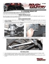
□ Complete the warranty form. The VMAC warranty form is located
at the back of this manual. This warranty form must be
completed and mailed or faxed to VMAC at the time of
installation for any subsequent warranty claim to be considered
valid.
System Identification and Operating Instructions
The System Identification Number Plate must be attached to the
vehicle at the time of installation (Figure 1.1). This plate provides
information that allows VMAC to assist in customer inquiries and the
ordering of parts.
□ Mark and drill two 7/64-inch holes in the top of the cross member
behind the passenger-side headlight. Secure the plate with the
supplied self tapping screws
□ Clean cross member beside the number plate and stick the
VMAC belt routing diagram to the cross member.
System ID number plate
Left Front
Figure 1.1

VMAC – Vehicle Mounted Air Compressors
Toll Free: 1-888-241-2289
Fax: 1-250-740-3201
6
□ As part of the installation process, ensure that the safety and
operational instruction decal is affixed in an obvious location so
that it can be seen by vehicle operators. A good spot for this is
usually on the inside of the door or on the panel underneath the
steering wheel. (Figure 1.2)
Figure 1.2

VMAC – Vehicle Mounted Air Compressors
Toll Free: 1-888-241-2289
Fax: 1-250-740-3201
7
□ To alert any technicians that may service the vehicle, affix the
servicing caution/contact label in the engine compartment near
the hood latch in a visible location. Thoroughly clean the
selected area before affixing the label (figure 1.3)
Figure 1.3

VMAC – Vehicle Mounted Air Compressors
Toll Free: 1-888-241-2289
Fax: 1-250-740-3201
8
Part 2: Preparing for Installation
Preparation for installation is very important. Missing an item can
cause problems in the installation or even damage to components.
Check off each item as it is completed so that you do not miss any
preparation steps.
Ensure that you have filled out the VMAC Warranty
Registration. Install the System Identification Number
Plate and Operational Instruction Decal. (Please see Part
1 for details).
Keep all removed and unused OEM items if the truck is to be
returned to original equipment.
This manual contains specific installation instructions
for different model years. Make sure that you read
these instructions before beginning the installation and
identify the sections that apply to your vehicle.
□ Drain the cooling system, remove the upper and lower radiator
hose and disconnect the coolant expansion tank hose from the
top of the radiator.
□ Disconnect the batteries and remove the passenger side battery.
□ Remove the plastic air deflector from the upper section of the fan
shroud. Keep this part if the vehicle is to be returned to stock
condition.
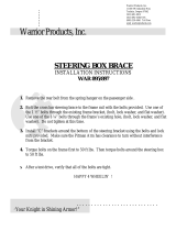
□ Remove the two screws securing the upper section of the fan
shroud to the radiator. There are two options for removing the
fan shroud (you can remove the air cleaner to make this easier):
a. Carefully pry the shroud upward to release the rubber seal
from the groove in the stator. Push the top corner of the
shroud back to clear the upper hose spigot and pull the
shroud out. Be careful not to crack the shroud.
b. Locate the molded lines on the fan shroud, one on each side
about 6 inches (15cm) down from the top (Figure 2.1). Use a
suitable tool to cut the fan shroud between these lines

VMAC – Vehicle Mounted Air Compressors
Toll Free: 1-888-241-2289
Fax: 1-250-740-3201
9
(Figure 2.1). Do not cut the rubber seal. Remove the upper
shroud section along with the rubber seal, then remove the
lower fan shroud section.
Upper shroud
Lower shroud
Rubber seal
Cut along molded line
Figure 2.1
□ Disconnect the fan clutch wiring harness from the fan stator and
the fan clutch wiring plug connector. Remove the fan.
□ Remove the rear fan stator (large plastic section with cooling fins
behind the fan) and store it for future use if the vehicle is to be
returned to stock condition.
□ Remove the four bolts from the water pump pulley and replace
them with the supplied low profile head bolts.
□ Remove the OEM serpentine belt.
□ Remove the OEM belt tensioner assembly.

VMAC – Vehicle Mounted Air Compressors
Toll Free: 1-888-241-2289
Fax: 1-250-740-3201
10
□ Remove the intercooler tube on the passenger side and keep the
2-1/2 inch OEM clamps. Discard the intercooler tube, the
connecting hose from the intercooler and the two larger T-bolt
clamps.
Cover the turbo outlet and the intercooler inlet to
protect the system.
□ Disconnect and remove the glow plug relay module with the
mounting bracket. Detach the module from the mounting bracket,
discard the bracket but keep the nuts.
□ Unscrew the engine oil fill tube. Plug the oil filler opening to
protect the engine.
□ On automatic transmission models, remove the transmission
dipstick from the passenger side valve cover and install the
supplied bracket (using the OEM nut) with the spacer facing
down and away from the valve cover. Attach the transmission
dipstick to the lower spacer of the bracket using the supplied
fasteners.
□ Remove the wiring harness retainers from the studs at the front
of the valve cover. Cut the tape back far enough so that you can
reroute the harness behind the transmission dipstick tube and
over the valve cover. Most of the wiring and the glow plug
connectors should be behind and below the alternator.
□ Cut off the upper threaded section of the two front valve cover
bolts (just below the alternator) flush with the hex nut.
□ Remove the steel heater return pipe with rubber O-ring. Save the
O-ring and the M6 bolt. Disconnect the steel pipe from the heater
hose and discard the pipe.
□ Install the OEM O-ring onto the replacement heater hose barb
connector and install it into the front of the engine where the
heater hose pipe was removed (Figure 2.2). Cut a short piece of
3/4 inch hose from the supplied 8 inch piece, fit it onto the hose
barb and secure it with a clamp.

VMAC – Vehicle Mounted Air Compressors
Toll Free: 1-888-241-2289
Fax: 1-250-740-3201
11
Figure 2.2
□ Insert the long end of the supplied replacement steel heater pipe
into the short 3/4" heater hose and position the short end with
the tab along the alternator, pointing toward the firewall.
□ If equipped, remove the sound proofing from the underside of the
hood.
□ Remove the plastic clips holding the flexible mud deflectors to
the top and bottom of the radiator cross-member.
□ For easier installation of the cooler, remove the bolts from the
small power steering cooler in front of the radiator cross-member
and leave it loose in position. You can also remove the radiator
hold-downs and raise the radiator for better access.
□ Some trucks may have a crossbeam behind the air dam and
under the radiator while others may have a crossbeam that also
retains the tow-hooks. This can be removed to provide easier oil
cooler installation.
2.2 Modifying the Passenger Side Battery Tray
□ Remove the passenger side battery tray.
□ Turn the battery tray over and cut off the fender bracket along
the bottom crease of the battery tray (Figure 2.3).

VMAC – Vehicle Mounted Air Compressors
Toll Free: 1-888-241-2289
Fax: 1-250-740-3201
12
Figure 2.3
□ Install the supplied battery bracket to the inner side of the
passenger fender using the two OEM M8 bolts (Figure 2.4).
□ Install the passenger side battery tray reversed 180 degrees and
fasten it in place with 5/16 x 1 inch bolts with 3/8 inch flat
washers and 5/16 inch lock washers and nuts. The battery tray
hold-down clamp should face to the rear of the vehicle and the
tray should be on a slight angle. Slide the tray as far forward as
possible.
You may have to trim off some of the plastic web on the
windshield washer bottle to clear the edge of the battery
tray.

VMAC – Vehicle Mounted Air Compressors
Toll Free: 1-888-241-2289
Fax: 1-250-740-3201
13
Battery bracket
Figure 2.4
□ Drill an 11/32 inch diameter hole through the OEM support
bracket using an existing hole in the battery tray as a guide.
Install a 5/16 x 1 inch bolt with 3/8 inch flat washer and 5/16 inch
lock washer and nut. Tighten all fasteners.
2.3 Mounting the Vacuum Tank
If the truck does not have air conditioning, you must
still relocate the vacuum tank on the plastic fender liner
to clear the compressor but will not have to replace the
short hose or use the mount bracket.
□ Remove the vacuum tank from the passenger side fender and
save the nuts for reinstallation.
□ Disconnect the hoses from the vacuum tank and discard the
short hose from the vacuum pump to the vacuum tank.
□ Remove the three bolts mounting the air conditioning
receiver/dryer from the heater housing.
If necessary, remove the fender liner for better access.

VMAC – Vehicle Mounted Air Compressors
Toll Free: 1-888-241-2289
Fax: 1-250-740-3201
14
□ Carefully bend the forward facing top larger air conditioning line
out towards the inner fender until parallel to the fender. Twist on
the vertical section while supporting the receiver/dryer canister
and push inwards. This can be accomplished using a long pry
bar protected where it rests between the two vertical sections of
the lines (Figure 2.5).
First bend
Support first
bend by pushing
here
Second bend
pull up on the
bottom of the
cannister toward
the front
Position the cannister in front of the wiring plug
Place the clamp above the electrical
connector facing forward
Figure 2.5
□ Bend the other line by pulling upward and forward on the
receiver/dryer canister to provide adequate clearance.
□ Remove and discard the plastic shroud from the receiver/dryer.
□ Remove the bolt and clamping components from the supplied
heavy duty clamp and slide the clamp up onto the receiver drier
with the open side towards the front of the vehicle, above the
electrical connection.
□ Install the clamping bolt in the clamp and through the vacuum
tank bracket. Leave the clamp loose enough so that you can
adjust the position (Figure 2.5).
□ Remove the front bolt holding the vacuum pump bracket to the
passenger side fender. Place the supplied vacuum tank bracket
in position over the OEM vacuum pump bracket and install the
OEM bolt.

VMAC – Vehicle Mounted Air Compressors
Toll Free: 1-888-241-2289
Fax: 1-250-740-3201
15
□ Mount the vacuum tank bracket using the original OEM M6 nuts
with the hose connections at the bottom, angled at approximately
45 degrees (Figure 2.6). If required, bend up OEM vacuum pump
and OEM vacuum pump bracket approximately 20 degrees to
clear the air conditioning condenser (Figure 2.7).
Figure 2.6
Figure 2.7

VMAC – Vehicle Mounted Air Compressors
Toll Free: 1-888-241-2289
Fax: 1-250-740-3201
16
□ Install the supplied 1/8 inch rubber hose between the vacuum
pump and the vacuum tank and connect the other hoses.
2.4 Glow Plug Modules
□ Mount the glow plug module to the supplied bracket using the
two OEM M6 nuts so that the module will face toward the center
of the engine when the bracket is installed.
□ Install the assembly on the passenger side engine valve cover
studs beside the engine oil fill-tube using OEM nuts.
□ Wrap any loose OEM wires with tape and connect the glow plug
relays. Make sure that the wire harness is secured behind the
alternator where it will not touch the compressor or turbocharger.
□ Install the oil fill tube.
2.5 Relocating the ICP Sensor
Bendthebatterytraytabup
Keep the flat on the bolt head horizontal
Figure 2.8
□ On trucks built after 2004.25, remove the ICP sensor from the
passenger side valve cover.

VMAC – Vehicle Mounted Air Compressors
Toll Free: 1-888-241-2289
Fax: 1-250-740-3201
17
Check the rubber seal in the valve cover for damage
and replace if necessary.
□ Install the sensor in the supplied banjo fitting and torque to 9
foot-lbs.
□ Install the banjo, with copper seal, into the valve cover. Attach
the electrical connector, position the fitting so that the sensor
points toward the turbo (towards the rear of the truck and up at
about a 45 angle), and torque the banjo fitting bolt to 20 ft-lbs.
Make sure that the OEM O-ring is on the sensor and do
not lose the copper sealing gasket on the supplied
banjo fitting. Make sure that the ICP sensor is properly
sealed and tightened to prevent oil leaks, as improper
installation and sealing can void OEM warranty.
□ Ensure that the top and bottom flats on the ICP bolt are
horizontal. If required, tighten the bolt slightly to make them
horizontal.
!
!

VMAC – Vehicle Mounted Air Compressors
Toll Free: 1-888-241-2289
Fax: 1-250-740-3201
18
Part 3: Installing the Tank and
Hoses
3.1 Installing the Brackets
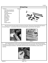
For 2005-2007 F450 – F550 model trucks see the special
installation instructions for the rear tank mount.
□ Remove the bolts, washers and nuts from the tank clamps.
□ Lay the tank brackets on a flat surface with the wide flanges
away from each other (Figure 3.1). The front and rear brackets
are different and are stamped “Front” and “Rear”.
Upper frame clip
Inner tank clamp
Lower frame clip
Spacer (not used on wide frames)
5/16” x 1/2”
Figure 3.1
□ Insert the cable straps through the upper frame clips and place
one cable on each tank bracket with the cables in the grooves.

VMAC – Vehicle Mounted Air Compressors
Toll Free: 1-888-241-2289
Fax: 1-250-740-3201
19
□ Place one inner tank clamp onto the front tank bracket. Apply
Loctite to the 5/16 x 1/2 inch hex head bolts (with flat washers)
and attach the inner clamp to the front tank bracket. Tighten all
the bolts.
3.1.1 All Trucks Except 2005 - 2007 F450 and F550
□ Place the inner tank clamp on the rear tank bracket. Apply
Loctite and attach the clamp to the bracket using 5/16 x 1/2 inch
hex head bolts. Tighten all the bolts.
□ Clean the area on the frame between the two cab mounts on the
passenger side and place the front bracket on the frame in front
of the transmission cross-member and as far forward on the
frame as possible. Place the upper frame clip on the frame rail
and make sure the frame seats in the groove.
□ Wrap the cable under the frame, insert the lower frame clip and
make sure the frame is seated in the clip. Install a spacer (if
necessary) a washer and a nut. Tighten the nut securely (do not
over-tighten) and install a second nut as a lock.
□ Place the rear bracket behind the transmission cross-member
and as far back as possible. Attach in the same manner as the
front bracket.
The tank brackets must be positioned far enough apart
to provide good support for the tank, but must not be
positioned in any location where the tank will not be
level when installed.
3.1.2 2005 - 2007 F450 and F550
□ Place spacers on the rear tank bracket as shown in Figure 2.2;
1/2 inch spacers on the top and bottom front holes, 5/8 inch
spacer on the top rear hole and a 3/4 inch spacer on the bottom
rear hole.
□ Place the inner tank clamp on the spacers, apply Loctite and
install 5/16 x 1 inch bolts with washers through the two front
holes, 1/2 inch spacers and into the bracket.

VMAC – Vehicle Mounted Air Compressors
Toll Free: 1-888-241-2289
Fax: 1-250-740-3201
20
□ Apply Loctite and install a 5/16 x 1-1/4 inch bolt with washer
through the top rear hole, 5/8” spacer and into the bracket.
□ Apply Loctite and install a 5/16 x 1-1/4 inch bolt with washer
through the bottom rear hole, 3/4 inch spacer and into the
bracket. Tighten all the bolts.
Rear tank bracket
Inner tank clamp
5/8” spacer
1/2” spacers
3/4” spacer
5/16” x 1”
5/16” x 1-1/4”
Figure 3.2
□ Clean the area on the frame between the two cab mounts on the
passenger side and place the front bracket on the frame as
shown in Figure 3.3. Place the upper frame clip on the frame rail
and make sure the frame seats in the groove.
□ Wrap the cable under the frame, insert the lower frame clip and
make sure the frame is seated in the clip. Install a spacer (if
necessary) a washer and a nut. Tighten the nut securely (do not
over-tighten) and install a second nut as a lock.
□ Place the rear bracket on the frame as shown in Figure 3.3 and
attach in the same manner as the front bracket.
/