Page is loading ...

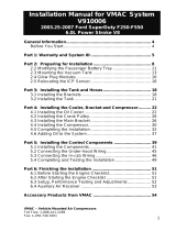
Installation Manual for
VMAC System V900097
2006 - 2007 GMC/Chevrolet 5.3L and 6.0L
Vortec Gas


VMAC – Truck Mounted Air Compressors
Toll Free: 1-888-241-2289
Fax: 1-250-740-3201
1
Installation Manual for VMAC
System V900097
2006 - 2007 GMC/Chevrolet 5.3L and 6.0L
Vortec Gas
General Information..................................................................... 4
Before You Start ....................................................................... 4
Special Tools Required ............................................................ 4
Hose Information ...................................................................... 4
Part 1: Warranty and System ID ................................................. 5
Part 2: Preparing for Installation ................................................ 7
2.1 Preparing for Installation .................................................... 7
Part 3: Installing the Control Components ............................... 11
3.1 Installing the Control Box ................................................... 12
3.2 Connecting the In-Cab Wiring ............................................ 12
3.3 Connecting the Under-Hood Wiring ................................... 14
Part 4: Installing the Tank and Hoses........................................ 16
4.1 Installing the Tank and Brackets ........................................ 16
4.2 Installing the Tank Assembly .............................................. 18
Part 5: Installing the Cooler, Bracket and Compressor ........... 21
5.1 Installing the Crank Pulley .................................................. 21
5.2 Installing the Oil Cooler ...................................................... 23
5.3 Installing the Main Bracket and Compressor ..................... 25
5.4 Connecting the Hoses ........................................................ 29
5.5 Completing the Installation ................................................. 31
Part 6: Adding Oil to the System ............................................... 33
Part 7: Finishing the Installation ................................................ 34
7.1 Connecting to Switched Power .......................................... 34
7.2 Securing the Wiring ............................................................ 35
Part 8 Completing and Testing the Installation ........................ 36
Safety Test ............................................................................... 36
Part 9: Finishing the Installation ................................................ 37
9.1 Before Starting the Engine Checklist.................................. 37
9.2 After Starting the Engine Checklist .................................... 37
9.3 Final Testing ....................................................................... 38
Part 10: Setup, Performance Testing and Adjustments ......... 39
Part 11: Optional Accessory Installation ................................. 40
Part 12: Auxiliary Air Receiver ................................................... 41
Part 13: Accessory Products ...................................................... 42

VMAC – Truck Mounted Air Compressors
Toll Free: 1-888-241-2289
Fax: 1-250-740-3201
2
Installation Manual for VMAC System V900097
2006 – 2007 GMC/Chevrolet Classic 5.3L and 6.0L Vortec Gas
Document 1930265
Changes and Revisions
Version
Revision Details
Revised by /date
Checked by /date
Reviewed by /date
Implemented
A
ECN 15-074
REF July 16 2015
-
-
-
B
ECN 15-090
REF July 22 2015
CJH 23 Dec 2015
MSP 23 Dec 2015
15 Jan 2016
Important Information
This symbol is used to call your attention to instructions
concerning your personal safety. Watch for this symbol; it
points out important safety precautions, it means “attention,
become alert! Your personal safety is involved. Read the
message that follows and be alert to the possibility of
personal injury or death. Be alert; your safety is involved.
While it is impossible to warn about every conceivable
hazard, let good common sense be your guide.
This symbol is used to call your attention to additional
instructions or special emphasis on a specific procedure.
The information in this manual is intended for certified VMAC installers
who have been trained in installation procedures and for people with
mechanical trade certification who have the tools and equipment to
properly and safely perform the installation. Do not attempt this
installation if you do not have the appropriate mechanical training,
knowledge and experience.
Follow all safety precautions for under hood mechanical work. Any
grinding, bending or restructuring operations for correct fit in modified
trucks must follow standard shop practices.
All hoses, tubes, and wires that are rerouted or shifted
during installation must be secure so that they do not
contact excessively hot areas or sharp edges. Where
possible, use rubber coated P-clips. Follow the routing
suggestions in this manual and cover all hoses with the
supplied plastic loom.

VMAC – Truck Mounted Air Compressors
Toll Free: 1-888-241-2289
Fax: 1-250-740-3201
3
These instructions are a general guide for installing this system on
standard production trucks and do not contain information for installation
on non-standard trucks. This system may not fit special order models or
those which have had other changes without additional modifications. If
you have difficulty with the installation, contact VMAC.
The VMAC warranty form is included in the documentation package.
This warranty form must be completed and mailed or faxed to VMAC at
the time of installation for any subsequent warranty claim to be
considered valid. Alternatively, the warranty form can also be found at:
http://vmacair.com/support/warranty
To order parts, contact your VMAC dealer. Your dealer will ask for the
VMAC serial number, part number, description and quantity. To locate
your nearest dealer, call 1-888-241-2289 or visit:
http://vmacair.com/dealer-locator/
Copyright 2015
All trademarks used in this manual are the property of the respective copyright holder.
The contents of this manual may not be reproduced in any form without the express written
permission of VMAC, 1333 Kipp Road, Nanaimo, BC V9X 1R3.
Printed in Canada

VMAC – Truck Mounted Air Compressors
Toll Free: 1-888-241-2289
Fax: 1-250-740-3201
4
General Information
Before You Start
Read this manual before attempting installation so that you can
familiarize yourself with the components and how they fit on the truck.
Identify variations for different model years and different situations that
are listed in the manual. Open the package, unpack the components and
identify them.
All fasteners must be torqued to specifications. Use manufacturers
torque values for OEM fasteners. Apply Loctite 242 or equivalent on all
engine-mounted fasteners. Torque values are with Loctite applied unless
otherwise specified.
STANDARD GRADE 8 NATIONAL COARSE THREAD
Size
1/4
5/16
3/8
7/16
1/2
9/16
5/8
¾
Foot-pounds (ft-lb)
9
18
35
55
80
110
170
280
Newton meter (N•m)
12
24
47
74
108
149
230
379
STANDARD GRADE 8 NATIONAL FINE THREAD
Size
3/8
7/16
1/2
5/8
¾
Foot-pounds (ft-lb)
40
60
90
180
320
Newton meter (N•m)
54
81
122
244
434
METRIC CLASS 10.9
Size
M8
M10
M12
M14
M16
Foot-pounds (ft-lb)
19
41
69
104
174
Newton meter (N•m)
25
55
93
141
236
Special Tools Required
OEM flywheel locking tool part number J42386.
Pneumatic fan wrench removal set (such as Lisle 43300) or a
manual fan pulley holder (such as KD3900)
Loctite 265
Hose Information
Depending on other installed equipment, it might be necessary to move
the air/oil separation tank from its intended location. The hoses used in
VMAC compressor systems have a specific inner liner that is compatible
with our compressor oil. Use of hoses other than those supplied or
recommended by VMAC may cause compressor damage and may void
your warranty. Please contact VMAC for replacement hoses and further
information.

VMAC – Truck Mounted Air Compressors
Toll Free: 1-888-241-2289
Fax: 1-250-740-3201
5
Part 1: Warranty and System ID
□ Complete the warranty form. The VMAC warranty form is
located at the back of this manual. This warranty form must be
completed and mailed or faxed to VMAC at the time of installation
for any subsequent warranty claim to be considered valid. This form
can also be found online at:
http://vmacair.com/support/warranty/
System Identification and Operating Instructions
The System Identification Number Plate must be attached to the vehicle
at the time of installation. This plate provides information that allows
VMAC to assist in customer inquiries and ordering of parts.
□ Mark and drill two 7/64-inch holes in the top of the cross member in
front of the OEM air filter box. Secure the plate with supplied self-
tapping screws. (Figure 1.1)
Passenger Side
Headlight
System Identification
Number Plate
Passenger Side
Fender
Figure 1.1 – System Identification Plate
□ Clean cross member beside the number plate and stick the VMAC
belt routing diagram to the cross member.
□ As part of the installation process, ensure that the safety and
operational instruction decal is affixed in an obvious location so that
it can be seen by vehicle operators. A good spot for this is usually
on the inside of the door or on the panel underneath the steering
wheel (Figure 1.2).

VMAC – Truck Mounted Air Compressors
Toll Free: 1-888-241-2289
Fax: 1-250-740-3201
6
Figure 1.2 – Operating Instructions
□ To alert any technicians that may service the vehicle, affix the
servicing caution/contact label in the engine compartment near the
hood latch in a visible location. Thoroughly clean the selected area
before affixing the label (Figure 1.3).
Figure 1.3 – Service label
To order parts, contact your VMAC dealer. Your dealer will ask for the
VMAC serial number, part number, description and quantity. To locate
your nearest dealer, call 1-888-241-2289 or visit www.vmacair.com

VMAC – Truck Mounted Air Compressors
Toll Free: 1-888-241-2289
Fax: 1-250-740-3201
7
Part 2: Preparing for Installation
2.1 Preparing for Installation
Preparation for installation is very important. Missing an item can cause
problems in the installation or even damage to components. Check off
each item as it is completed so that you do not miss any preparation
steps.
□ Remove the plastic cover from the top center of the engine.
□ If the truck has an automatic transmission, locate the wiring harness
that runs up from the transmission and over the center of the engine
intake manifold, through the trough on the driver’s side of the intake
(Figure 2.1). Remove the harness from the protective loom, cut the
tape open and locate the light green wires in the bundle.
Locate light green wire
in this harness
Figure 2.1
There are two light green wires in the bundle. Only one
of the wires can be used for system control.

VMAC – Truck Mounted Air Compressors
Toll Free: 1-888-241-2289
Fax: 1-250-740-3201
8
□ Turn on the ignition switch and probe the green wires.
□ The correct wire will show 12 Volts in PARK and 0 Volts in all other
gear selector positions.
□ Turn the ignition switch off. Mark the wire for electrical connections
later in the installation process.
□ Disconnect the battery terminals and remove the battery.
□ Remove the battery mounting plate.
□ Remove the bracket holding the large, red battery cable splitter box
from the alternator and power steering pump bracket. Keep the two
M6 OEM cap screws.
□ Unclip the large wiring harness from the driver side valve cover and
the small wiring harness attached to the red battery cable splitter
box bracket.
□ Remove the driver side fender liner.
□ Remove the Power Train Control Module (PCM) from the driver side
fender (do not disconnect the wiring) and place the module out of
the way.
□ Bend the PCM locating tab on the fender down so that it is flush with
the surface (Figure 2.2).
Figure 2.2

VMAC – Truck Mounted Air Compressors
Toll Free: 1-888-241-2289
Fax: 1-250-740-3201
9
□ Remove the air intake tube and resonator box.
□ Drain the coolant.
□ Remove the radiator end of the top OEM radiator hose, unclip it
from the fan shroud and move it out of the way.
□ Remove the upper radiator fan shroud.
□ Remove the fan assembly and the lower radiator fan shroud.
□ Remove the engine end of the lower radiator hose.
□ Remove the OEM belt
□ Mark the position of the power steering pump pulley in relation to the
pump shaft and remove the pulley with a recommended puller.
□ Remove the power steering pump. Remove the support bracket
from the back of the power steering pump and bend the tab that
attaches to the side of the engine block upwards about 5 degrees to
align with the compressor bracket. Install the modified bracket onto
the power steering pump.
□ Disconnect the wiring and remove the alternator.
□ Remove the OEM aluminum alternator and power steering pump
mounting bracket.
□ Remove the OEM back idler from the bracket.
□ Clean the inside of the OEM crankshaft pulley and remove the OEM
crankshaft pulley center bolt.
□ Clean the driver side of the engine. Check all threaded holes to
make sure that they are clean and free from damage. Clean the
frame on the passenger side of the truck between the two body
mounts.
□ If equipped, remove the fuel line from the plastic clips so that it can
be moved out of the way when mounting the tank.

VMAC – Truck Mounted Air Compressors
Toll Free: 1-888-241-2289
Fax: 1-250-740-3201
10
□ If equipped, remove the OEM wire harness securing bracket from
the top of the frame so that it can be moved out of the way when
mounting the tank.
□ Remove both OEM fasteners from the fender support bracket on the
passenger side of the truck (Figure 2.4). On four-wheel drive trucks,
remove the hex head bolt on the bottom of the frame that holds the
tow hook in place. Some trucks may have a hole in the frame where
the tow hook would be attached.
Remove these bolts
Front of truck
Passenger side fender
Figure 2.4
□ Replace the fasteners with the supplied low profile M10 x 30 mm
hex head bolts with flat washers, as the high profile head on the
OEM bolt will interfere with the cooler bracket.

VMAC – Truck Mounted Air Compressors
Toll Free: 1-888-241-2289
Fax: 1-250-740-3201
11
Part 3: Installing the Control
Components
White
Interface
Connector
Green 4 pin
connector
White
Red
Red
Red Red
White
White
White
Compressor
Inlet valve
Clutch
Green
Green
Black
OEM
FUSE
PANEL
Black 3 pin
connector
To ground
Park brake
switch
141
21
61
545
25
65
10
50
30
70
15
55
35
75
20
60
40
80
Power Control Module (PCM)
Solder and seal
Connect
Throttle
Controller
Throttle
Controller
Connect to
accelerator pedal
OEM Connector from
accelerator pedal
To ground
Blue
Blue
Blue
Blue
AUTOMATIC TRANSMISSION
Solder long blue wire to light green
wire in vehicle harness from
the transmission
Do not use short blue wire with
crimp connector
MANUAL TRANSMISSION
Connect the blue wires
Throttle
Controller
Blue
Blue
FIREWALL
Blue with white stripe - Pin 12
Control Box
Figure 3.1 - Wiring Diagram V900097

VMAC – Truck Mounted Air Compressors
Toll Free: 1-888-241-2289
Fax: 1-250-740-3201
12
3.1 Installing the Control Box
□ Locate a suitable location for the control box where it will be
accessible but will not be subject to damage.
□ Mount the control box with the wire harness coming out the bottom
or the back of the unit. If the control box is mounted to the body
panel, remove the plastic door trim and route the wiring along the
body panel under the trim and up under the dash.
□ Mount the throttle control box under the dash using plastic ties.
Select a location that will allow access to the adjusting screws.
3.2 Connecting the In-Cab Wiring
□ Connect the interface wire harness connector to the matching
connector from the control box.
□ Disconnect the multi-pin connector from the accelerator pedal and
plug it into to the matching connector at the throttle control box then
plug the connector from the throttle control box into the accelerator
pedal.
□ Connect the wires with the ring connector from the throttle control
box and from the interface connector to a good metal ground under
the dash.
□ Connect the red wire from the interface connector to the red wire
from the throttle control box.

VMAC – Truck Mounted Air Compressors
Toll Free: 1-888-241-2289
Fax: 1-250-740-3201
13
□ Route the following wires through a suitable firewall plug under the
dash. If necessary, cut a slit in one of the rubber plugs and pull the
wires through into the engine compartment.
cable with the black 3 pin connector
cable with the green 4 pin connector
white wire with the bullet connector
white wire from the throttle control box
□ Remove the cover from the fuse panel and route the red wire with
the fuse tap/holder to the panel. Refer to section 7.1 Connecting
to Switched Power for connection details.
□ Unplug the connector from the park brake switch. You may have to
remove the cover from the large OEM electrical connector located
on the firewall of the truck next to the park brake to gain access to
the connection. Connect the OEM park brake connector to the
supplied piggyback connector.
3.2.1 Manual Transmission Trucks
□ Cut the long blue wire to about 6 inches, strip the end and connect it
to the short blue wire using the attached crimp connector.
3.2.2 Automatic Transmission Trucks
□ Route the long blue wire through the same location that you used for
the other wires.

VMAC – Truck Mounted Air Compressors
Toll Free: 1-888-241-2289
Fax: 1-250-740-3201
14
3.3 Connecting the Under-Hood Wiring
□ Remove the black plastic cover from the PCM unit on the driver’s
side fender and carefully remove the innermost grey plastic wiring
protector.
You can unclip the PCM and rotate it to make finding
the wires easier.
□ Locate pin 12 on the wiring connector. It should have a blue wire
with a white stripe (Figure 3.3).
1
41
21
61
5
45
25
65
10
50
30
70
15
55
35
75
20
60
40
80
#12 dark blue wire with a white stripe
Figure 3.3
□ Cut the electrical tape holding the wire loom over the harness and
pull the loom back to expose the wiring.
Be careful not to damage or cut the wires.
□ Cut the electrical tape on the bundle of wires to access the blue wire
with the white stripe as far back from the PCM as possible.
□ Cut the wire and remove about 1/2 inch of insulation from the ends.
Slide a piece of shrink sleeve over one end.
□ Remove about 1 inch of insulation from the throttle control box white
wire. Join the wires, solder and seal with the shrink sleeve. The
preferred method is shown in Figure 3.4.

VMAC – Truck Mounted Air Compressors
Toll Free: 1-888-241-2289
Fax: 1-250-740-3201
15
OEM wire
Throttle wire
Shrink sleeve
Soldered joint
Figure 3.4
□ Replace the tape over the bundle. Fit the loom back over the
harness and tape it in place. Replace the plastic wiring protector and
the black plastic cover.
□ Cut the light green wire (marked during preparation) and remove
about 1/2 inch of insulation from each end. Slide a shrink sleeve
over one end of the wire.
□ Remove about 1 inch of insulation from the throttle control box blue
wire, join the wires, solder and seal the joint. The preferred method
is shown in Figure 3.4.
□ Replace the tape on the bundle. Fit the loom back over the harness
and tape it in place.
□ Install the plastic cover on the engine.

VMAC – Truck Mounted Air Compressors
Toll Free: 1-888-241-2289
Fax: 1-250-740-3201
16
Part 4: Installing the Tank and
Hoses
4.1 Installing the Tank and Brackets
The tank will mount to the passenger side frame rail
between the two body mounts (Figure 4.1).
1/4” and 3/16” tubes
3/4” hose fitting
1/2” hose fitting
C-clamp
Tank strap mount
Upper frame clip
Tank strap cable
Lower frame clip
Spacer
Oil filter
5/16” nuts and
washer
Figure 4.1
□ Place the tank on a work bench with the front (oil filter end) of the
tank to your left. Remove the oil filter from the front of the tank.
□ Remove the two 1/4 inch clamp bolts from the C-clamps. Expand
the clamps slightly and slide them over the front of the tank.
□ Position the C-clamps about 6 inches from each end of the tank.
□ Place the two L-shaped tank strap mounts under the C-clamps with
the right-angle ends facing you and hanging over the edge of the
work bench.

VMAC – Truck Mounted Air Compressors
Toll Free: 1-888-241-2289
Fax: 1-250-740-3201
17
□ Align the holes, apply Loctite and thread 5/16 x 1/2 inch bolts with
flat washers into the bottom hole on each bracket, but do not
tighten.
□ Install the 1/4 inch clamp bolts into the C-clamps so that the heads
of the bolts face toward you and install the nuts.
□ Rotate the tank so that the directional arrow on the end of the tank is
parallel to the work bench and faces toward you (Figure 4.2).
□ Check the distance of each C-clamp from the ends of the tank and
tighten the clamp bolts so that the clamps grip the tank securely.
Figure 4.2
□ Apply Loctite and insert 5/16 x 1/2 inch bolts through the clips and
the C-clamp and thread them into the mount brackets.
□ Center the bolts in the C-clamp slots and tighten them.
□ Thread the 1/2 inch and 3/4 inch swivel elbows onto the matching
fittings on the front of the tank, but do not tighten them.

VMAC – Truck Mounted Air Compressors
Toll Free: 1-888-241-2289
Fax: 1-250-740-3201
18
□ Apply Loctite pipe thread sealant and install a fitting to the outlet on
the tank. A 90 degree fitting is recommended. Tighten it to about the
four o’clock position for testing, then reposition as required for final
connections (Figure 4.3).
Figure 4.3
4.2 Installing the Tank Assembly
□ Insert the threaded end of the cable strap through the single hole
end of the bar straps.
□ Place the bar straps in position on the inside of the frame, one in
front of the transmission cross-member and one behind, with the
cable straps over the top of the frame (Figure 4.4).
□ Lift the tank assembly and support it in position so the tops of the
two strap mounts fit over the top of the frame rail.
Make sure that the OEM wire harness is outside the
mounts and is not pinched between the mounts and
the frame.
/