Page is loading ...

VR70 UNDERHOOD
AIR COMPRESSOR
INSTALLATION MANUAL
System V900130
2011-2016 FORD F250-F550 6.7L Diesel


VMAC – Vehicle Mounted Air Compressors
Toll Free: 1-888-241-2289
Fax: 1-250-740-3201
1
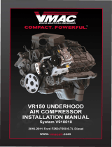
VR70 UNDERHOOD AIR
COMPRESSOR INSTALLATION
MANUAL
System V900130
2011 - 2016 F250-F550
6.7L Power Stroke Diesel
General Information ........................................................................... 5
Before You Start ............................................................................... 5
Torque Specifications ....................................................................... 5
Special Tools Required ..................................................................... 5
Important Safety Notice .................................................................... 6
Safety Messages .............................................................................. 6
Ordering Parts ................................................................................... 7
Warranty Registration ....................................................................... 7
Part 1: Warranty and System ID ........................................................ 8
System ID and Operating Instructions .............................................. 8
Part 2: Preparing for Installation ..................................................... 10
2.1 Preparing for Installation ........................................................... 10
Part 3: Installing the Tank ................................................................ 12
Part 4: Modifying the Lower Radiator Hoses, Installing the Cooler,
and Connecting the Oil Hoses ........................................................ 18
Modifying the Lower Radiator hoses ............................................... 18
Installing the Cooler ........................................................................ 20
Installing the Cooler Oil Hoses ........................................................ 22
Part 5: Installing the Crank Pulley .................................................. 23
Additional belt routing diagrams ...................................................... 24
Part 6: Installing the Main Bracket and Fan Stator ........................ 25
Installing the Main Bracket .............................................................. 25
Installing the Main Bracket on Dual Alternator ................................ 31
Modifying and Installing the Fan Stator ........................................... 35
Alternator wire relocation and Insulation ......................................... 36

VMAC – Truck Mounted Air Compressors
Toll Free: 1-888-241-2289
Fax: 1-250-740-3201
2
Part 7: Installing the Compressor, Inlet Valve and Pressure
Sensor and Control Line .................................................................. 37
Installing the Compressor ............................................................... 37
Installing the Pressure Sensor ........................................................ 38
Installing the Inlet Valve .................................................................. 39
Installing the Control Line ............................................................... 40
Part 8: Installing the Insulation and Compressor Hoses .............. 41
Installing the Insulation ................................................................... 41
Installing the Compressor Discharge Hose..................................... 44
Installing the PTFE® hoses ............................................................ 49
Installing the Compressor Oil Return Hose..................................... 50
Part 9: Installing the Compressor Belt, Fan, and Fan Shroud ..... 51
Installing the Compressor Belt ........................................................ 51
Installing the Fan ............................................................................ 52
Installing the Fan Shroud ................................................................ 53
Part 10: Modifying the Battery Box and Intercooler ...................... 57
Modifying and Installing the Battery Box ......................................... 57
Modifying the Charge Air Cooler ..................................................... 59
Installing the Charge Air Cooler ...................................................... 61
Part 11: Adding Oil to the System ................................................. 62
Part 12: Installing the Intercooler Hoses, and Compressor Air
Filter ................................................................................................... 63
Installing the Remote Air Filter Bracket .......................................... 63
Heater hose from CAC straight spigot ............................................ 64
Cold Side Charge-Air-Cooler (CAC) Piping .................................... 66
Hot Side Charge-Air-Cooler (CAC) Piping ...................................... 73
Charge-Air-Cooler Clamp Orientation ............................................. 75
Installing the Remote Filter Hose .................................................... 76
Heater hose from CAC 90deg Spigot ............................................. 77
Part 13: Modifying the Upper Radiator Hose and Connector ...... 81
Modifying the Upper Radiator Hose ................................................ 81
Modifying the Upper Radiator Connector ....................................... 86
Part 14: Installing the Battery Cable Bracket and Cables ........... 93
Installing the Battery Cable Bracket ................................................ 93
Routing the Battery Cables ............................................................. 97

VMAC – Vehicle Mounted Air Compressors
Toll Free: 1-888-241-2289
Fax: 1-250-740-3201
3
Part 15: Installing the Battery Box ............................................... 101
Alternative Battery Mounting Locations ........................................ 103
Part 16: Installing the Control Components ................................ 104
Installing the Components ............................................................ 105
Routing the In-cab wiring .............................................................. 105
Connecting the In-cab wiring ........................................................ 106
Part 17 Completing and Testing the Installation ......................... 108
Completing the Installation ............................................................ 108
Safety Test .................................................................................... 109
Part 18: Finishing the Installation ................................................. 110
18.1 Before Starting the Engine Checklist .................................... 110
18.2 After Starting the Engine Checklist ....................................... 110
18.3 Final Testing ......................................................................... 111
Part 19: Setup, Performance Testing and Adjustments ............ 112
Part 20: Optional Accessory Installation ..................................... 113
Part 21: Auxiliary Air Receiver ...................................................... 114
Part 22: Accessory Products ......................................................... 115

VMAC – Truck Mounted Air Compressors
Toll Free: 1-888-241-2289
Fax: 1-250-740-3201
4
VR70 UNDERHOOD AIR COMPRESSOR INSTALLATION MANUAL
SYSTEM V900130
2011 - 2016 Ford F250 - F550 6.7L Power Stroke Diesel
Document 1930229
Changes and Revisions
Version
Revision Details
Revised by/date
Checked by/date
Reviewed by/date
Implemented
A
Engineering Release
MC 7 Oct 2014
MP 30 Jan 2015
RD 30 Jan 2015
5 Feb 2015
B
ECN 15-008
RF 13 Mar 2015
PD 21 Apr 2015
RD 23 Apr 2015
27 Apr 2015
C
ECN 15-059
REF 26 October 2015
CJH 5 Nov 2015
JPC 5 Nov 2015
5 Nov 2015
Important Information
The information in this manual is intended for certified VMAC installers
who have been trained in installation procedures and for people with
mechanical trade certification who have the tools and equipment to
properly and safely perform the installation. Do not attempt this
installation if you do not have the appropriate mechanical training,
knowledge and experience.
Follow all safety precautions for mechanical work. Any grinding,
bending or restructuring operations for correct fit in modified trucks must
follow standard shop practices.
Notice
Manuals are subject to change without notice.
Registered Trademarks
All trademarks mentioned in this manual are the property of their
respective owners. Their use by VMAC is for identification of the
manufacturers’ products only and does not imply any affiliation or
endorsement by said companies.
Loctite, Klean N’ Prime, 242 and PST are registered trademarks of
Henkel AG & Company KGaA.
PTFE is a registered trademark of E. I. du Pont de Nemours and
Company or its affiliates.
Nylok is a registered trademark of Nylok Fastener Corporation.
Copyright 2016
All trademarks used in this manual are the property of the respective copyright
holder. The contents of this manual may not be reproduced in any form without the
express written permission of VMAC, 1333 Kipp Road, Nanaimo, BC V9X 1R3.
Printed in Canada

VMAC – Vehicle Mounted Air Compressors
Toll Free: 1-888-241-2289
Fax: 1-250-740-3201
5
General Information
Before You Start
Read this manual before attempting installation so that you can
familiarize yourself with the components and how they fit on the
vehicle. Identify variations for different engine models and different
situations that are listed in the manual. Open the package, unpack the
components and identify them.
Torque Specifications
All fasteners must be torqued to specifications. Use manufacturers
torque values for OEM fasteners. Apply Loctite 242® or equivalent
on all engine-mounted fasteners. Torque values are with Loctite
applied unless otherwise specified.
STANDARD GRADE 8 NATIONAL COARSE THREAD
Size
1/4
5/16
3/8
7/16
1/2
9/16
5/8
3/4
Foot-pounds
(ft-lb)
9
18
35
55
80
110
170
280
Newton meter
(N•m)
12
24
47
74
108
149
230
379
STANDARD GRADE 8 NATIONAL FINE THREAD
Size
3/8
7/16
1/2
5/8
3/4
Foot-pounds (ft-lb)
40
60
90
180
320
Newton meter (N•m)
54
81
122
244
434
METRIC CLASS 10.9
Size
M8
M10
M12
M14
M16
Foot-pounds (ft-lb)
19
41
69
104
174
Newton meter (N•m)
25
55
93
141
236
Special Tools Required
Pneumatic fan wrench removal set (such as Lisle 43300) or a
manual fan pulley holder (such as KD3900)
M6 x 1.0 Die
Hose Information
Depending on other installed equipment, it might be necessary to
move the air/oil separation tank from its intended location. The hoses
used in VMAC compressor systems have a specific inner liner that is
compatible with our compressor oil. Use of hoses other than those
supplied or recommended by VMAC may cause compressor damage
and may void your warranty. Please contact VMAC for replacement
hoses and further information.

VMAC – Truck Mounted Air Compressors
Toll Free: 1-888-241-2289
Fax: 1-250-740-3201
6
Important Safety Notice
The information contained in this manual is based on sound engineering
principles, research, extensive field experience and technical
information. Information is constantly changing with the addition of new
models, assemblies and service techniques. If a discrepancy is noted
in this manual, contact VMAC prior to initiating or proceeding with
service. Current information may clarify the issue. Any person with
knowledge of such discrepancies who performs service and repair
assumes all risks.
Only proven service procedures are recommended. Anyone who
departs from the specific instructions provided in this manual must first
assure that their safety and that of others is not being compromised and
that there will be no adverse effects on performance or the operational
safety of the equipment.
VMAC will not be held responsible for any liability, injuries, loss or
damage to individuals or to equipment as a result of the failure of any
person to properly adhere to the procedures set out in this manual or
standard safety practices. Safety should be your first consideration in
performing service operations. If you have any questions concerning
the procedures in this manual or require any more information on details
that are not included in this manual, please contact VMAC before
beginning repairs.
Safety Messages
This manual contains various warnings, cautions and notices that must
be observed to reduce the risk of personal injury during service or repair
and the possibility that improper service or repair may damage the
equipment or render it unsafe.
This symbol is used to call your attention to instructions
concerning your personal safety. Watch for this symbol; it
points out important safety precautions, it means, “Attention,
become alert! Your personal safety is involved”. Read the
message that follows and be alert to the possibility of personal
injury or death. Be alert; your safety is involved. While it is
impossible to warn about every conceivable hazard, let good
common sense be your guide.
This symbol is used to call your attention to instructions on a
specific procedure that if not followed may damage or reduce
the useful life of the compressor.
This symbol is used to call your attention to additional
instructions or special emphasis on a specific procedure.

VMAC – Vehicle Mounted Air Compressors
Toll Free: 1-888-241-2289
Fax: 1-250-740-3201
7
Ordering Parts
To order parts, contact your VMAC dealer. Your dealer will ask for the
VMAC serial number, part number, description and quantity. To locate
your nearest dealer, call 1-800-738-8622 or online at
www.vmacair.com
Warranty Registration
The VMAC warranty form is located at the back of this manual. This
warranty form must be completed and sent to VMAC at the time of
installation for any subsequent warranty claim to be considered valid.
There are four ways warranty forms can be submitted to VMAC:
Online
http://vmacair.com/support/warranty/
Email
Fax
(250) 740-3202
Mail
VMAC - Vehicle Mounted Air Compressors
1333 Kipp Road, Nanaimo, BC, Canada V9X 1R3

VMAC – Truck Mounted Air Compressors
Toll Free: 1-888-241-2289
Fax: 1-250-740-3201
8
Part 1: Warranty and System ID
Check off each item as it is completed so that you do not
miss any preparation steps.
□ Check through the illustrated parts list, ensure that no components
are missing, and that they are in the correct quantity. If any
components are missing, have the system ID ready and call VMAC
tech support at (888) 241-2289.
□ Complete the warranty form. The VMAC warranty form is located
at the back of this manual, as well as online at:
http://vmacair.com/support/warranty/
This warranty form must be completed and mailed or faxed to
VMAC at the time of installation for any subsequent warranty claim
to be considered valid.
System ID and Operating Instructions
The System Identification Number Plate must be attached to the
vehicle at the time of installation. This plate provides information that
allows VMAC to assist in customer inquiries and ordering of parts.
□ Install battery warning label to driver side primary coolant
reservoir.
□ Mark and drill two 7/64-inch holes in the top of the cross member
in front of the OEM air filter box. Secure the plate with supplied
self- tapping screws (Figure 1.1).
Figure 1.1 – System Identification Tag
□ Clean cross member beside the number plate and stick the VMAC
belt routing diagram to the cross member.

VMAC – Vehicle Mounted Air Compressors
Toll Free: 1-888-241-2289
Fax: 1-250-740-3201
9
□ As part of the installation process, ensure that the safety and
operational instruction decal is affixed in an obvious location so
that it can be seen by vehicle operators. A good spot for this is
usually on the inside of the door or on the panel underneath the
steering wheel (Figure 1.2).
Figure 1.2 – Operating Instructions
□ To alert any technicians that may service the vehicle, affix the
servicing caution/contact label in the engine compartment near
the hood latch in a visible location. Thoroughly clean the selected
area before affixing the label (Figure 1.3).
Figure 1.3 – Service Label

VMAC – Truck Mounted Air Compressors
Toll Free: 1-888-241-2289
Fax: 1-250-740-3201
10
Part 2: Preparing for Installation
2.1 Preparing for Installation
Ensure that you have filled out the VMAC Warranty
Registration. Install the System Identification Number
Plate and Operational Instruction Decal. (Please see
Part 1 for details).
□ Locate the blunt-cut OEM SEIC wire harness, on the driver’s side
just below the OBDII port. You will need to find the transmission
park signal, (blue with grey stripe wire).
□ Use a multi-meter to verify the transmission park signal. Turn the
key to the IGN2 position, (do not start the truck), so as to supply
power to the dash display. The resistance should read close to 0-
ohms in park and open circuit in all other gears. If this is correct,
put the vehicle in park and turn the key to the off position.
There are multiple blue wires with various coloured
stripes. The transmission park signal needs to be
electrically verified with a multi-meter to ensure the
correct wire is read.
□ Mark transmission park signal wire for connection later in installing
control components section.
□ Disconnect batteries, (both driver and passenger side).
□ Drain coolant from both the primary and secondary radiators,
(drain for primary coolant on driver’s side, secondary coolant on
passenger side). Start with the secondary radiator, (drain on
passenger side). Save coolant to be reused later. Close drain
when coolant has been drained. The primary coolant drain is
easiest to access by removing the front bumper from the
vehicle.
□ Remove driver’s side battery bracket and battery. Save the J-
bolts and fasteners as they will be used again.
□ Remove driver’s side battery box and primary coolant reservoir.
□ Disconnect hoses from secondary coolant reservoir, (attached to
passenger side of fan shroud), and remove reservoir from fan
shroud.

VMAC – Vehicle Mounted Air Compressors
Toll Free: 1-888-241-2289
Fax: 1-250-740-3201
11
□ Remove air box for easier access to secondary coolant hoses.
This also allows access to the lower primary radiator hose for
removal.
□ Remove upper secondary coolant hose, (top hose going to water
pump on passenger side of engine).
□ Remove bolt securing power steering reservoir to upper fan
shroud. DO NOT remove the hoses from the reservoir. Slide
reservoir up out of clip securing it to the upper fan shroud.
□ Remove 5 bolts (3 on driver’s side and 2 on passenger side) and
wire clips securing upper fan shroud and remove upper fan
shroud from truck.
□ Unplug fan wire (unplug connector closer to the engine).
Remove long bolt securing fan wiring harness to engine and
discard. A spacer and longer bolt will be installed in this location
later in the install.
□ Remove the fan (right-hand thread) and pull it out of the engine
bay. For ease of fan removal and installation, it is
recommended that a pneumatic fan wrench removal set
(such as Lisle 43300) or a manual fan pulley holder
(such as KD3900) is used.
□ Remove fan stator by rotating it to clear the lower lip of the lower
fan shroud. It is not necessary to remove the lower fan
shroud.
□ Remove upper driver’s side fan stator mount from the engine and
save for use later.
□ Release tension on OEM belt (leave belt routed correctly on
passenger side of engine).
□ Remove cold air charger coolant tubing.
□ Remove cold air charger 3” air tubing.
□ Remove cold air charger and battery box.
□ Optional: Remove passenger and driver’s side fender liner.

VMAC – Truck Mounted Air Compressors
Toll Free: 1-888-241-2289
Fax: 1-250-740-3201
12
Part 3: Installing the Tank
The tank will mount on the passenger side frame rail
under the cab and must be level. Variations in frame
design may affect the positioning of the brackets.
Always check fitment before tightening the fasteners.
□ The tank will mount to the passenger side frame rail behind the
suspension radius arm mount (Figure 3.1).
Figure 3.1 – Tank Brackets
□ Remove one of the two OEM Nuts attaching the transmission
cross-member to the frame. Depending on the truck configuration
cross-member location may differ (Figure 3.2).
Figure 3.2 – OEM Cross Member Nut
Leave all tank mounts and fasteners loosened
throughout the following aligning process to make
adjustments easier.

VMAC – Vehicle Mounted Air Compressors
Toll Free: 1-888-241-2289
Fax: 1-250-740-3201
13
□ Install front mount bracket with 5/16-inch X 2 bolt holding the front
of the mount to the frame and re-use the OEM transmission cross-
member nut (Figure 3.1) (Figure 3.2).
□ Apply blue Loctite® and thread the top bolt into the rear tank
mount bracket. Ensure the tank clip is hooked over the backside
of the frame and no wires or tubes are pinched or trapped (Figure
3.3)
Figure 3.3 – Tank Brackets Exploded View
□ Install the tank clip so it hooks around the back of the frame.
Insert the threaded end through the appropriate hole in the bottom
of the rear tank strap. Apply blue Loctite® and start the 3/8 flange
nut on the tank clip (Figure 3.4).
Figure 3.4 – Tank Clips

VMAC – Truck Mounted Air Compressors
Toll Free: 1-888-241-2289
Fax: 1-250-740-3201
14
□ Install front and rear c-clamps onto the brackets using the top 5/16
x 1/2” bolt and washer only, tighten but do not torque as the
bracket will need to be adjusted later in the installation (Figure
3.5).
Figure 3.5 – Tank c-clamps
□ Slide the front of the tank through rear bracket first, then through
front bracket (Figure 3.6).
Figure 3.6 – Sliding Tank

VMAC – Vehicle Mounted Air Compressors
Toll Free: 1-888-241-2289
Fax: 1-250-740-3201
15
□ Align the weld on the front of the tank with the edge of the c-clamp
(Figure 3.7).
Figure 3.7 – Clamp and Weld Alignment
□ Rotate the tank so that the directional arrow on the end of the tank
is pointing upwards (Figure 3.9).
□ Install front pinch bolt downward through the top of the c-clamp,
install the serrated nut on the bottom (Figure 3.8).
Figure 3.8 – Front Pinch Bolt

VMAC – Truck Mounted Air Compressors
Toll Free: 1-888-241-2289
Fax: 1-250-740-3201
16
□ Install rear pinch bolt downward through the top of the c-clamp,
install the serrated nut on the bottom (Figure 3.9).
Figure 3.9 – Rear Pinch Bolt
Tank orientation is critical, if the arrow is not pointing
up you may get oil in the discharge air, or compressor
failure due to oil starvation (Figure 3.9).
□ Install front and rear lower C-clamp bolts loosely (Figure 3.10).
Figure 3.10 – Bottom c-clamp fasteners


VMAC – Truck Mounted Air Compressors
Toll Free: 1-888-241-2289
Fax: 1-250-740-3201
18
Part 4: Modifying the Lower
Radiator Hoses, Installing the
Cooler, and Connecting the Oil
Hoses
Modifying the Lower Radiator hoses
Separate the coupler in between the lower coolant
hose, to drain any remaining coolant in the hose.
□ Remove lower primary coolant hose, attached to the primary
radiator and engine (Figure 4.1).
To
Engine
From
Radiator
Figure 4.1 – Lower Primary Radiator Hose
Disconnect
coupler first
/