Page is loading ...

World Class Design | World Class Function | 30 Years Expertise In Industrial Motor Control
APPLICATION MANUAL:
HG102957 ISS3
340i 680i 1220i

340i / 680i / 1220i Applications 2
NOTE. These instructions do not purport to cover all details or variations in equipment, or to provide for every
possible contingency to be met in connection with installation, operation, or maintenance. Should further
information be desired or should particular problems arise which are not covered sufficiently for the purchaser's
purposes, the matter should be referred to the local Supplier sales office. The contents of this document shall
not become part of or modify any prior or existing agreement, commitment, or relationship. The sales contract
contains the entire obligation of Sprint Electric Ltd. The warranty contained in the contract between the parties
is the sole warranty of Sprint Electric Ltd. Any statements contained herein do not create new warranties or
modify the existing warranty.
HEALTH AND SAFETY AT WORK
Electrical devices can constitute a safety hazard. It is the responsibility of the user to ensure the compliance of
the installation with any acts or bylaws in force. Only skilled personnel should install and maintain this
equipment. If in doubt refer to the supplier.
Note. The contents of this document are believed to be accurate at the time of printing. The manufacturers,
however, reserve the right to change the content and product specification without notice. No liability is
accepted for omissions or errors. No liability is accepted for the installation or fitness for purpose or
application of the 340i / 680i / 1220i motor drive units.
1 Table of contents
1 Table of contents ....................................................................................... 2
2 340i Block Diagram and terminal listing. ............................................................ 3
3 Typical applications..................................................................................... 8
3.1
ON OFF switch with ramp to stop or coast to stop................................................................. 8
3.2
Zero reference interlock and Stop / Start pushbuttons. ......................................................... 9
3.3
Using an external 4-20mA speed signal ............................................................................ 10
3.4
Torque control ........................................................................................................... 11
3.5
Load sharing slave single direction. ................................................................................. 12
3.6
Low voltage speed feedback .......................................................................................... 13

340i / 680i / 1220i Applications 3
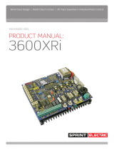
2 340i Block Diagram and terminal listing.
1 +10V output. 10mA max. (Use a 10K Ohm pot for external speed reference).
2 MIN SPEED. (Bottom end of external pot. 5K Ohms preset to common).
3 IP. Speed input. 0 to +/-10V speed input from pot wiper. 47K internal pull down.
4 OP+/-. +/-10.5V range. Input from T6. Invert with pushbutton input T8 open. Non-
invert with pushbutton input T7. 10mA max.
5 COM. Common. (0 Volts)
6 IP+/-. Input to pushbutton controlled +/- signal channel. OP on T4. 50K Ohms
impedance for invert mode, 10M input impedance in non-invert mode.
Note. This channel can invert input signals in the range +/-10.5V. It can also buffer
(i.e. non-invert) signals in the range 0V to +10.5V. (It cannot buffer negative signals.
If you try to buffer a negative signal the output will be positive).
Note. If using a high resistance external pot for positive signals e.g. greater than
20KOhms, then this channel can be used to buffer it using the non-invert mode.
7 PB+ Pushbutton input. 47K Ohm pull up to +12V. Connect to T5 COM. Latches T4 to
buffer (non-invert) positive T6 signals when opened, provided T8 PB- is connected to
T5 COM.
8 PB- Pushbutton input. 47K Ohm pull up to +12V. Connect to T5 COM. Latches T4 to
invert T6 when opened. T7 PB+ may be open or connected to T5 COM.
See truth table below for T7 and T8 operation. See terminal 6 IP+/- for notes.
PB+ Terminal 7
PB- Terminal 8
Input T6 to output T4 mode
Closed to Common
Open circuit
Invert (+/-10.5V range)
Closed to Common
Closed to Common
Remains in prevailing mode.
Powers up in invert mode.
Open circuit
Closed to Common
Non-invert (0 to +10.5V range)
Open circuit
Open circuit
Invert (+/-10.5V range)
a) Hence if PB+ Terminal 7 remains open then a switch on PB- Terminal 8 can be
used to change modes.
+
10V Min IP OP+/-
COM
IP+/- PB+ PB- RUN COM Tach
1
2
3
4 5
6
7
8
9 10
11 12 13 14 15 16 17 18 19 20 21
RLOP RLIP OVLD TRIP ROP
DEM SOP IOP SPD TRQ
L
N
F+
F -
A-
A+
Invert
Non-invert
OP IP
5
K
Up / Down Ramp
OP on T16. ROP
Speed P+I error
amplifier with
stability preset.
Output provides
current demand.
Arm Amps
Isolation
Amplifier.
IOP on T19
Max Current
Preset
Total speed
demand DEM
on T17 (-ve)
Speed Output
SOP on T18
Arm Volts
Isolation
Amplifier
X 2
30 Sec Stall timer
with logic outputs
TRIP on T15 and
Overload on T14
Current
Demand
Clamp.
0 - 5V on
T21 =
0 -100%
+12V
Centre zero comparator with window
threshold from +/-50mV to +/-10.5V
Goes high on T12 (0-10V. 10mA) if
+/- signal input T13 exceeds window.
+12V
.1
M
12
K
Current P+I error
amp with phase
angle controlled
anti-parallel
bridge.
340i/680i/1220i
AC 240V or 110V
Field coil
Armature.
For armatures
with a time
constant of
less than 5mS
a DC choke
must be wired
in series.
AC supply must be
semi-conductor fused.

340i / 680i / 1220i Applications 4
b) If both PB+ Terminal 7 and PB- Terminal 8 remain open then the invert mode is
established.
c) If both PB+ Terminal 7 and PB- Terminal 8 are connected to common then the
desired mode can be established by momentarily opening PB+ Terminal 7 for non-
invert, or PB- Terminal 8 for invert mode. The mode remains latched when the
common connection is re-established. This is useful for end of travel reversal. To
implement, connect T1 +10V to T6 IP+/- and use the T4 OP+/- as the reference to
the external max speed pot. Then connect the normally closed contacts from
microswitches on the track, to the pushbutton inputs T7 PB+ and T8 PB- such that
when the load reaches and opens the microswitch it toggles the reference in the
opposite direction.
9 RUN. Internal 12K pull up to +12V. Open to stop, close to COMMON to run. WARNING.
RUN is an electronic inhibit function. The field remains energised, and all power
terminals ‘live’. RUN must not be relied on to ensure the machine is stationary
during hazardous operations. Remove the power source to the system.
Opening T9 RUN will cause immediate drive inhibit and hence if the motor is
rotating at the time it will coast to zero speed.
10 COM. Common. (0 Volts)
11 TACH input. The tach must be opposite polarity to speed input. 1.5 MOhms.
12 RLOP. Relay driver. +10.5V active high. Flywheel diode to COM.
Note. The output is current limited. When in current limit, the output voltage
achieved, depends on the resistance of the load multiplied by the available current
limit at that voltage, according to the table below.
Output voltage
Typical current limit available
Typical Load resistance
10.5V
1mA
Greater than 10K Ohms
10.0V
10 mA
1000 Ohms
9.5V
15 mA
633 Ohms
9.0V
20 mA
450 Ohms
8.5V
25mA
340 Ohms
8.0V
30mA
267 Ohms
Below 8V
30 mA
Less than 267 Ohms
When driving relays, ensure the coil operating range is suitable. E. g. a 12V relay
with a coil operating range of 80-110% will energise at voltages of 9.6V and above
(80% of 12V). Hence it must have coil resistance greater than 633 Ohms for the
output to be capable of achieving the desired voltage. (See table above).

340i / 680i / 1220i Applications 5
Diagram of relay driver output stage
13 RLIP. Relay driver input. Accepts 0 to +/- 10.5V signal inputs. The threshold to
activate the relay driver is symmetrical around zero, and set by the RELAY preset
between +/- 0.05V and +/-10.5V. When the T13 input exceeds the positive or
negative threshold, then the T12 RELAY DRIVER OUTPUT is turned ON. Typical uses
include zero speed detector, zero current detector, stall detector etc.. The
input will accept any output provided on other control terminals. 50K Ohm pull
down to common.
Flywheel diode,
47K resistor and
47nF capacitor
LM324
+12V
Output
termina
l
This diode allows
relay outputs to
be OR'd together
if desired,
LM324
+12V
T12
RLOP
Flywheel diode,
47K resistor and
47nF capacitor
LM324
+12V
-
+
-
+
invert
10.5V
T13
RLIP
Level preset range
0.5% to 105%

340i / 680i / 1220i Applications 6
14 OVLD. Overload. This output goes high (+10.5V) if the current demand exceeds 100%
and the stall timer starts timing. Flywheel diode to COM. See T12 RLOP for details
of the output drive capability and configuration.
Note. It stays high if the overload subsequently results in a stall trip condition.
The stall timer will allow 150% motor current for approximately 30 seconds before
tripping. The overload integrator can tolerate 50% overload x 30 secs = 1500 units.
(A 50% overload is 150% of motor current set on Imax)
Available overload time prior to trip = 1500 / Overload % in seconds
Examples.
Other overload times 125% Imax current for 60 secs (1500 / 25 =60)
112.5% Imax current for 120 secs. (1500 / 12.5 =120)
For the overload capability to be fully restored after an overload that has not
resulted in a trip, the load must require an equivalent overload current% x time
below the 100% motor current rating.
E.g. If the load stayed at 150% for 15 seconds, then returned to 100% the overload
integrator has used up half of its available units. To reset the integrator to zero
again the load would have to run at say 50% for 15 seconds, or 99% for 750 seconds
for example.
Note. The 100% level for the stall timer is set automatically by the Imax preset.
The stall lamp will get progressively brighter as the stall timer integrates. It will be
completely extinguished when the stall timer integrator is empty. I.e. Full overload
capability available.
Note. The stall timer is actuated by current demand exceeding 100% when the
desired speed remains unsatisfied. E.g. Excess load, insufficient supply volts, loss of
feedback, saturated feedback, insufficient torque, jammed shaft. This allows the
protection to be more comprehensive than overcurrent alone.
15 TRIP. This output goes high (+10.5V) and latches high when the stall timer has timed
out (in which case T14 OVLD will also be high) OR if the fan alarm has operated (in
which case T14 OVLD will be low). Flywheel diode to COM. See T12 RLOP for details
of the output drive capability and configuration.
16 ROP. Ramp output. 0 to +/-10V output for 0 to +/-10V input. 1K Ohm output
impedance.
17 DEM. Demand output. 0 to -/+10V output for 0 to +/-100% speed demand.
1K Ohm output impedance. Represents the inverted total speed demand.
18 SOP. Speed output. 0 to +5V output for 0 to +100% speed feedback. 1K Ohm output
impedance. NOTE: Prior to LA issue 11 (see side of terminal block), the output at
this terminal was 0 to +10V.
19 IOP. Current output. 0 to +5V output for 0 to +100% armature current. Maximum
output +7.5V for +150% current. 1K Ohm output impedance.
20 SPD. Auxiliary speed input. Added to main input. Input impedance 100
0 to +/-10V input for 0 to +/-100% speed demand, direct input fast response.

340i / 680i / 1220i Applications 7
21 TRQ. Torque input. 100K Ohms pull up to +12V.
0 to +5V input for 0 to +/-100% current demand. This input acts as a clamp on the
current demand produced by the speed loop. Also if the speed loop current demand
falls below the input clamp level then the speed loop has priority. For the clamp to
operate, the speed loop current demand must be arranged to exceed the clamp
level by ensuring the speed demand is high enough.
A+ Motor armature + Form Factor typically 1.5
A- Motor armature -
F- Motor Field – (No connection required for permanent magnet motors).
F+ Motor Field +(For half wave field volts 0.45 X AC, connect field to F- and N).
N AC supply. 110V AC or 240V AC +/-10%, 50–60 Hz.
L AC supply. 110V AC or 240V AC +/-10%, 50–60 Hz.

340i / 680i / 1220i Applications 8
3 Typical applications
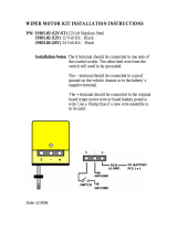
3.1 ON OFF switch with ramp to stop or coast to stop
The +10V ref is connected to the speed pot by a switch giving a ramp to zero when opened.
Note. The AVF/tach select switch must be set, and the appropriate speed scale range selected for the max
feedback volts, depending on the source of speed feedback.
If a tachogenerator is used the polarity on T11 must be negative.
Acw
10K
Pot
Cw
Run or ramp to
Stop switch.
RUN switch. Close
to COMMON. Open
for coast to STOP.
Optional TACH
for speed
feedback.
Optional speed
indicator. +5V =
100%
Optional current
indicator. +7V5 =
150%
Semi-
conductor
fuse.
2 pole AC
supply
switch
+
10V Min IP OP+/-
COM
IP+/- PB+ PB- RUN COM Tach
1
2
3
4 5
6
7
8
9 10
11 12 13 14 15 16 17 18 19 20 21
RLOP RLIP OVLD TRIP ROP
DEM SOP IOP SPD TRQ
L
N
F+
F -
A-
A+
Invert
Non-invert
OP IP
5
K
Up / Down Ramp
OP on T16. ROP
Speed P+I error
amplifier with
stability preset.
Output provides
current demand.
Arm Amps
Isolation
Amplifier.
IOP on T19
Max Current
Preset
Total speed
demand DEM
on T17 (-ve)
Speed Output
SOP on T18
Arm Volts
Isolation
Amplifier
X 2
30 Sec Stall timer
with logic outputs
TRIP on T15 and
Overload on T14
Current
Demand
Clamp.
0 - 5V on
T21 =
0 -100%
+12V
Centre zero comparator with window
threshold from +/-50mV to +/-10.5V
Goes high on T12 (0-10V. 10mA) if
+/- signal input T13 exceeds window.
+12V
.1
M
12
K
Current P+I error
amp with phase
angle controlled
anti-parallel
bridge.
340i/680i/1220i
AC 240V or 110V
Field coil
Armature.
For armatures
with a time
constant of
less than 5mS
a DC choke
must be wired
in series.
AC supply must be
semi-conductor fused.

340i / 680i / 1220i Applications 9
3.2 Zero reference interlock and Stop / Start pushbuttons.
With the unit powered up and the reference above the threshold set by the relay driver level preset, the signal
relay will be energised, and the contact will be closed. Hence the Start pushbutton is inoperative. When the
operator brings the external reference to zero, the the signal relay will de-energise and the Start pushbutton will
be operative.
Then, when the Start pushbutton is closed, and providing the Stop pushbutton is also closed, the 2 pole relay will
energise. This will latch in the Start condition and close the RUN line. The drive can now be operated at any
speed until the Stop pushbutton is pressed. In order to start, the operator must once more ensure the external
reference is zero.
Start pushbutton.
Acw
10K
Pot
Cw
Speed pot
with 10V
reference.
Relay
S
Relay
Stop pushbutton.
2 pole N.O. relay. (The coil and contacts should be
snubbered using a 0.1uF cap in series with 100R.)
1 pole N.C. relay
+
10V Min IP OP+/-
COM
IP+/- PB+ PB- RUN COM Tach
1
2
3
4 5
6
7
8
9 10
11 12 13 14 15 16 17 18 19 20 21
RLOP RLIP OVLD TRIP ROP
DEM SOP IOP SPD TRQ
L
N
F+
F -
A-
A+
Invert
Non-invert
OP IP
5
K
Up / Down Ramp
OP on T16. ROP
Speed P+I error
amplifier with
stability preset.
Output provides
current demand.
Arm Amps
Isolation
Amplifier.
IOP on T19
Max Current
Preset
Total speed
demand DEM
on T17 (-ve)
Speed Output
SOP on T18
Arm Volts
Isolation
Amplifier
X 2
30 Sec Stall timer
with logic outputs
TRIP on T15 and
Overload on T14
Current
Demand
Clamp.
0 - 5V on
T21 =
0 -100%
+12V
Centre zero comparator with window
threshold from +/-50mV to +/-10.5V
Goes high on T12 (0-10V. 10mA) if
+/- signal input T13 exceeds window.
+12V
.1
M
12
K
Current P+I error
amp with phase
angle controlled
anti-parallel
bridge.
340i/680i/1220i
AC 240V or 110V
Field coil
Armature.
For armatures
with a time
constant of
less than 5mS
a DC choke
must be wired
in series.
AC supply must be
semi-conductor fused.

340i / 680i / 1220i Applications 10
3.3 Using an external 4-20mA speed signal
The 4-20mA floating source is imposed across a burden resistor of value 316 Ohms. (Standard E96 value).
This creates a voltage of 1.26 Volts at 4mA across the resistor. This represents the system zero.
The 10K Ohm resistor is used in conjunction with the Min speed preset to provide a reference of 1.26 volts which
is then inverted in the +/- channel.
The burden resistor is referred to the -1.26V source from T4 and hence the voltage created at 4mA on the speed
input T3 is zero volts as required.
With 20mA flowing (which represents 100% speed) the voltage across the burden is 6.32 Volts. This provides a
speed signal of 6.32 - 1.26 = 5.06 Volts on T3.
The T16 Ramp output is linked to T20 speed input to double the speed input strength and hence the 5V speed
reference will provide the standard speed scaling range.
For 0 - 20mA sources use a 249 Ohm burden resistor and refer it to common instead of -1.26 Volts.
This resistor
creates 1.26V
reference on T2
4-20mA burden
resistor.
This node is
at -1.26V
10K Ohms
Resistor
316 Ohm
Resistor
Isolated 4-20mA
Current
loop source
4-20mA speed
reference.
+
10V
Min
IP
OP+/-
COM
IP+/-
PB+
PB-
RUN
COM
Tach
1
2
3
4
5
6
7
8
9
10
11
12
13
14
15
16
17
18
19
20
21
RLOP
RLIP
OVLD
TRIP
ROP
DEM
SOP
IOP
SPD
TRQ
L
N
F+
F -
A-
A+
Invert
Non-invert
OP IP
5
K
Up / Down Ramp
OP on T16. ROP
Speed P+I error
amplifier with
stability preset.
Output provides
current demand.
Arm Amps
Isolation
Amplifier.
IOP on T19
Max Current
Preset
Total speed
demand DEM
on T17 (-ve)
Speed Output
SOP on T18
Arm Volts
Isolation
Amplifier
X 2
30 Sec Stall timer
with logic outputs
TRIP on T15 and
Overload on T14
Current
Demand
Clamp.
0 - 5V on
T21 =
0 -100%
+12V
Centre zero comparator with window
threshold from +/-50mV to +/-10.5V
Goes high on T12 (0-10V. 10mA) if
+/- signal input T13 exceeds window.
+12V
.1
M
12
K
Current P+I error
amp with phase
angle controlled
anti-parallel
bridge.
340i/680i/1220i
AC 240V or 110V
Field coil
Armature.
For armatures
with a time
constant of
less than 5mS
a DC choke
must be wired
in series.
AC supply must be
semi-conductor fused.

340i / 680i / 1220i Applications 11
3.4 Torque control
T21 is 0 to +5V input for 0 to 100% current demand. This torque signal acts as a clamp on the current demand
produced by the speed loop.
If the speed loop current demand falls below the input clamp level then the speed loop will regain control at a
speed lower than the clamp level allows. For the clamp to operate, the speed loop current demand must be
arranged to exceed the clamp level by ensuring the speed demand is high enough.
Speed pot with
10V reference
Acw
10K
Pot
Cw
Torque pot with
5V reference
This resistor is used to
reduce the torque ref
range to 5V max.
RUN switch. Close to
COMMON. Open for
coast to STOP.
Acw
10K
Pot
Cw
10K Ohms
Resistor
+
10V Min IP OP+/-
COM
IP+/- PB+ PB- RUN COM Tach
1
2
3
4 5
6
7
8
9 10
11 12 13 14 15 16 17 18 19 20 21
RLOP RLIP OVLD TRIP ROP
DEM SOP IOP SPD TRQ
L
N
F+
F -
A-
A+
Invert
Non-invert
OP IP
5
K
Up / Down Ramp
OP on T16. ROP
Speed P+I error
amplifier with
stability preset.
Output provides
current demand.
Arm Amps
Isolation
Amplifier.
IOP on T19
Max Current
Preset
Total speed
demand DEM
on T17 (-ve)
Speed Output
SOP on T18
Arm Volts
Isolation
Amplifier
X 2
30 Sec Stall timer
with logic outputs
TRIP on T15 and
Overload on T14
Current
Demand
Clamp.
0 - 5V on
T21 =
0 -100%
+12V
Centre zero comparator with window
threshold from +/-50mV to +/-10.5V
Goes high on T12 (0-10V. 10mA) if
+/- signal input T13 exceeds window.
+12V
.1
M
12
K
Current P+I error
amp with phase
angle controlled
anti-parallel
bridge.
340i/680i/1220i
AC 240V or 110V
Field coil
Armature.
For armatures
with a time
constant of
less than 5mS
a DC choke
must be wired
in series.
AC supply must be
semi-conductor fused.

340i / 680i / 1220i Applications 12
3.5 Load sharing slave single direction.
Load sharing is used when a large load is driven by more than 1 motor and each motor must bear the load in the
same proportion. The motors are linked mechanically via the load and usually rotate at the same speed.
T21 requires a 0 to +5V input for 0 to 100% current demand. This torque acts as a clamp on the current demand
produced by the speed loop. The signal is derived from the master drive T19 current output. Hence whatever
current is required by the master will also be provided by the slave.
To ensure that the current demand of the slave is always clamped by the torque input a 1V (10%) speed signal is
added to the direct speed input. This is derived from an external 10K resistor and the Min speed preset.
The main speed reference is sourced from the master T16 ramp output.
This 1V level is used to ensure the
speed demand is always 10% more
than the master speed.
This resistor is used
with Min Speed preset
to provide 1V.
This signal is from
T19 IOP of the
master drive.
10K Ohms
Resistor
The common of the
master and slave must
be connected.
This signal is from
T16 Ramp output
from the master.
+
10V Min IP OP+/-
COM
IP+/- PB+ PB- RUN COM Tach
1
2
3
4 5
6
7
8
9 10
11 12 13 14 15 16 17 18 19 20 21
RLOP RLIP OVLD TRIP ROP
DEM SOP IOP SPD TRQ
L
N
F+
F -
A-
A+
Invert
Non-invert
OP IP
5
K
Up / Down Ramp
OP on T16. ROP
Speed P+I error
amplifier with
stability preset.
Output provides
current demand.
Arm Amps
Isolation
Amplifier.
IOP on T19
Max Current
Preset
Total speed
demand DEM
on T17 (-ve)
Speed Output
SOP on T18
Arm Volts
Isolation
Amplifier
X 2
30 Sec Stall timer
with logic outputs
TRIP on T15 and
Overload on T14
Current
Demand
Clamp.
0 - 5V on
T21 =
0 -100%
+12V
Centre zero comparator with window
threshold from +/-50mV to +/-10.5V
Goes high on T12 (0-10V. 10mA) if
+/- signal input T13 exceeds window.
+12V
.1
M
12
K
Current P+I error
amp with phase
angle controlled
anti-parallel
bridge.
340i/680i/1220i
AC 240V or 110V
Field coil
Armature.
For armatures
with a time
constant of
less than 5mS
a DC choke
must be wired
in series.
AC supply must be
semi-conductor fused.

340i / 680i / 1220i Applications 13
3.6 Low voltage speed feedback
The output on T17 is the inverted total speed demand. By connecting this into T20 the feedback scaling is
reduced to 50% for both armature voltage and tacho feedback.
Hence:
With Spd x 2 switch OFF (right) maximum speed feedback range = 20 to 50V.
With Spd x 2 switch ON (left) the maximum speed feedback range = 40 to 100V.
The speed output T18 will now provide 0 to +/-5V for 0 to +/-100% speed.
CAUTION should be exercised if using this technique with armature voltage feedback as a way of operating a low
voltage motor from a relatively high voltage drive (e.g. 48V motor, 240V drive): The poor form-factor
experienced by the motor in such cases may lead to reduced brush life and increased operating temperature. It is
also possible, in the case of a permanent magnet motor, that demagnetisation will occur.
In such applications, it is preferable to match the AC supply to the DC armature voltage more closely. This may
be achieved by the use of a low voltage drive, powered from a step-down transformer (e.g. 48V motor, LV60
drive, 240V to 60V auto-transformer). Please contact Sprint Electric Ltd if more information is required.
HG102957 Iss 3a, 14/02/18. Address corrected
Connect T17 DEM
to T20 SPD
Acw
10K
Pot
Cw
+
10V Min IP OP+/-
COM
IP+/- PB+ PB- RUN COM Tach
1
2
3
4 5
6
7
8
9 10
11 12 13 14 15 16 17 18 19 20 21
RLOP RLIP OVLD TRIP ROP
DEM SOP IOP SPD TRQ
L
N
F+
F -
A-
A+
Invert
Non-invert
OP IP
5
K
Up / Down Ramp
OP on T16. ROP
Speed P+I error
amplifier with
stability preset.
Output provides
current demand.
Arm Amps
Isolation
Amplifier.
IOP on T19
Max Current
Preset
Total speed
demand DEM
on T17 (-ve)
Speed Output
SOP on T18
Arm Volts
Isolation
Amplifier
X 2
30 Sec Stall timer
with logic outputs
TRIP on T15 and
Overload on T14
Current
Demand
Clamp.
0 - 5V on
T21 =
0 -100%
+12V
Centre zero comparator with window
threshold from +/-50mV to +/-10.5V
Goes high on T12 (0-10V. 10mA) if
+/- signal input T13 exceeds window.
+12V
.1
M
12
K
Current P+I error
amp with phase
angle controlled
anti-parallel
bridge.
340i/680i/1220i
AC 240V or 110V
Field coil
Armature.
For armatures
with a time
constant of
less than 5mS
a DC choke
must be wired
in series.
AC supply must be
semi-conductor fused.

Find out more:
www.sprint-electric.com
Sprint Electric Ltd. Peregrine House, Ford Lane, Ford
Arundel, West Sussex, BN18 0DF United Kingdom
Tel: +44 (0)1243 558080
Fax: +44 (0)1243 558099
Email: [email protected]
/