Page is loading ...

World Class Design | World Class Function | 30 Years Expertise in Industrial Motor Control
Product Manual
HG105266EN00 Issue 1 (02/2021)
DC MOTOR DRIVE
340 / 680 / 1220

Please read this information before installing or using the product.
Install, use and maintain this product following the procedures provided.
The manual(s) cannot provide all details, variations and contingencies required for your
installation, operation and maintenance of this product or the apparatus with this product
installed. For further help or information, refer to your local Supplier sales offi ce.
Application area
The equipment described is intended for industrial (non-consumer) motor speed control.
Intended users
To safely enable the user to obtain maximum benefi t from the equipment:
• Ensure this information is available to all persons required to install, confi gure or service
the described equipment or any other associated operation.
• Always store the manual in a conveniently accessible area for quick reference.
• Make it available for the next user/owner of the product.
Safety
Ensure all users and operators understand the included WARNINGS, CAUTIONS and
NOTES, which alert the user to safety issues. COMPLY WITH WARNINGS AND CAUTIONS
AT ALL TIMES. Each of these carries a special meaning and should be read carefully:
WARNING!
A WARNING is given when non-compliance with the warning may result in
personal injury and/or equipment damage.
CAUTION!
A CAUTION is given when non-compliance with the caution may result in
permanent equipment damage.
NOTE A note provides specifi c information to make important instructions clear.
Symbols
Attention Electrostatic
Discharge (ESD)
Electric Shock
Hazard
See the instructions for use.
Specifi c warnings not found
on the label.
This equipment contains
ESD sensitive parts. Observe
static control precautions
when handling, installing
and servicing this product.
Disconnect the mains
supply before working on
the unit.
Do not touch presets,
switches and jumpers!
Always use the correct
insulated adjustment tools.
This product is of the restricted sales distribution class according to IEC 61800-3
and has a "professional equipment" designation as defi ned in EN 61000-3-2.

Installation
• Ensure mechanically secure fi xings are in use as recommended.
• Ensure cooling airfl ow around the product is as recommended.
• Ensure cables/wire terminations are as recommended and are torqued correctly.
• Ensure the product rating is correct - do not exceed the rating.
Application risk
Electromechanical safety is the responsibility of the user. The integration of this product
into other apparatus or systems is not the manufacturer's or distributor of the product's
responsibility. It is the user's responsibility to ensure the compliance of the installation with
any regulations in force.
Health and safety at work
Electrical devices can constitute a safety hazard. Thorough personnel training is an aid
to SAFETY and productivity. SAFETY awareness not only reduces the risk of accidents and
injuries in your plant but also has a direct impact on improving product quality and costs.
If you have any doubts about the SAFETY of your system or process, consult an expert
immediately. Do not proceed without doing so. If in doubt, refer to the Supplier.
CAUTION!
EQUIPMENT DAMAGE HAZARD
• We thoroughly test our products. However, before installation and start-up,
inspect all equipment for transit damage, loose parts, packing materials, etc.
• Installation must observe the required environmental conditions for safe and
reliable operation.
• In a domestic environment, this product may cause radio interference, requiring
adequate measures to be taken. Obtain the permission of the supply authority
before connecting to the low voltage supply.
WARNING!
PERSONAL INJURY AND/OR ELECTRICAL SHOCK HAZARD
• Always isolate all power supplies from the equipment before starting any work.
• Never perform high voltage resistance checks on the wiring without fi rst
disconnecting the product from the circuit under test.
• Use guarding and additional safety systems to prevent injury and electric shock.
• Metal parts may reach 90°C during operation.
Hazards
This equipment can endanger life through rotating machinery and high voltages.
WARNING!
Only qualifi ed personnel must install, operate and maintain this equipment.
A qualifi ed person is someone technically competent and familiar with all safety
information, established safety practices, installation, operation, maintenance
and the hazards involved with this equipment and any associated machinery.
General risks

Weight
Consideration should be given to the weight of our heavier products when handling.
Risk assessment
Under fault conditions or conditions not intended: the motor speed may be incorrect; the
motor speed may be excessive; the direction of rotation may be incorrect; the motor may be
energised.
In all situations, the user should provide suffi cient guarding and/or additional redundant
monitoring and safety systems to prevent risk of injury.
NOTE: During a power loss event, the product will commence a sequenced shut-down
procedure. Therefore, the system designer must provide suitable protection for this case.
Maintenance
Only qualifi ed personnel should maintain and effect repair using only the recommended
spares, alternatively return the equipment to the factory for repair. The use of unapproved
parts may create a hazard and risk of injury.
WARNING!
PERSONAL INJURY AND/OR EQUIPMENT DAMAGE HAZARD
When replacing a product, all user-defi ned parameters that defi ne the product's
operation must be installed correctly before returning to use. Failure to do so
may create a hazard and risk of injury.
The packaging is infl ammable and incorrect disposal may lead to the generation
of lethal toxic fumes.
Repairs
Repair reports can only be given if the user makes suffi cient and accurate defect reporting.
Remember that the product without the required precautions can represent an electrical
hazard and risk of injury, and that rotating machinery is a mechanical hazard.
Protective insulation
Non-isolated product
WARNING!
The motor must be connected to an appropriate safety earth.
Failure to do so presents an electrical shock hazard. Exposed metal work in this
equipment is protected by basic insulation and bonding to a safety earth.
This product is classifi ed as a component and must be used in a suitable enclosure.
1. There is no isolation between the Power and Control Circuits. ALL connections to
the Drive are HAZARDOUS. Mount the drive in an earthed enclosure.
2. The Installer MUST provide Protection for the End User by using Double or
Re-inforced Insulation. The drive's Control signal terminals operate at the output
voltage of the drive. Therefore, User controls MUST be made safe by the use of suitably
insulated components, i.e. Potentiometer, Run Switch.
3. DO NOT connect these Control signal terminals to low voltage equipment or any
non-isolated potential as this will cause signifi cant damage to both the Drive and
attached equipment.

Contents:
1 Introduction 11 Introduction 1
2 Installation 22 Installation 2
2.1 Motor installation .......................................................................................................... 2
2.2 Drive installation ........................................................................................................... 2
2.2.1 Initial settings - without power .....................................................................2
2.2.2 Mechanical installation ..................................................................................4
2.2.3 Electrical installation ......................................................................................4
3 Operation 63 Operation 6
3.1 Pre-operation motor check list .................................................................................... 6
3.2 Operating the drive ....................................................................................................... 6
4 Options 84 Options 8
5 Specications 95 Specications 9

1 1
IntroductionIntroduction
The 340 / 680/ 1220 DC Drive is a non-isolated speed controller for small brushed shunt
wound or permanent magnet DC motors.
This "non-isolated" drive has control signals that are NOT isolated from the mains supply,
therefore, do not connect any of the terminals to earth or to other non-isolated equipment
as when power is applied to the drive ALL terminals are at dangerous line potential.
To control the motor speed the drive uses speed feedback derived from either the armature
voltage or a shaft-mounted tachogenerator. It incorporates an accurate current control loop
to protect itself and the motor.
Current loop: full P+I current shunt feedback
Speed loop: full P+I armature voltage or tach feedback
Speed range: 0-100% (motor dependent)
Load regulation: typically 0.2% Tacho, 2% Armature Volts
The LV60 sux, for example 340 LV60, denotes a low voltage version.
This component is hazardous. Please obtain expert help if you are not qualied to
install this equipment. Make safety a priority.
Read about the general risks and warnings at the front of this manual.
This apparatus complies with the protection requirements of the relevant EU
Directives. UL le: E168302.
WARNING!
PERSONAL INJURY HAZARD
This product is non-isolated and so, when power is applied to the drive, ALL
terminals are at dangerous line potential.
Ensure that connected items (e.g. speed potentiometer, Tacho etc.) are NOT
earthed, and have sucient dielectric strength to avoid breakdown.
1
Introduction

2 2
InstallationInstallation
2.1
Motor installation
• Foot-mounted motors must be level and secure.
• Ensure accurate alignment of the motor shaft and couplings.
• Do not hammer pulleys or couplings onto the motor shaft.
• Protect the motor from ingress of foreign matter during installation.
NOTE: This drive does not provide motor over-temperature protection. If required, t
an external thermal sensor device to the motor that will remove the supply when activated
by over-temperature.
Earthing: Connect the motor to the system enclosure earth.
2.2
Drive installation
Requirements during installation and operation:
• Avoid vibration.
• Protect the drive from pollutants.
• Avoid ambient temperatures below –10°C and above +40°C. To comply with UL
requirements, the temperature of the surrounding air must not exceed 50ºC.
• The heat dissipation of the drive in Watts approximates to 5 x Armature Current
value in Amps. Ensure there is an adequate supply of clean cool air to ventilate the
unit and the enclosure it is mounted in.
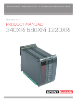
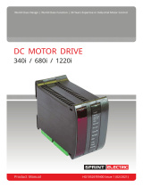
2.2.1
Initial settings - without power
1. To avoid damage, ensure the supply selection jumper on the
drive matches the incoming ac supply: 240 Vac or 110 Vac,
(60 Vac or 30 Vac for LV60 models).
2. With the unit on the work bench, open the red cover on the front of the drive by
inserting a small screwdriver at the bottom of the cover.
3. Set the I MAX preset to match the motor armature current rating as closely as possible:
• fully anti-clockwise = 0%
• fully clockwise = 100% of the drive rating,
i.e. 3.4 A (340 drive), 6.8 A (680 drive), 12.2 A (1220 drive)
For example, to adjust the preset on a 340 drive for a motor with an armature
current rating of 1.7 A, set it to 50%. Use a suitable current meter temporarily
connected in series with the armature to achieve accurate settings.
4. Set Max spd, Min spd, Ramp and IR comp presets to fully anti-clockwise.
5. The preferred strategy for initial commissioning is to use the armature voltage feedback
mode. To use armature voltage feedback:
• set the Avf/Tach switch to ON (left)
• set the Spd x 2 switch to OFF (right)
(Temporarily remove any tachogenerator connection made to Terminal 6. Make the wire
end safe until later).
DANGER!
ELECTRIC
SHOCK
HAZARD
MOTOR
ARMATURE
MOTOR
FIELD
AC SUPPLY
10K
fuse
1
+10
2
MIN
3
I/P
4
COM
5
RUN
6
TACH
A+
A-
F-
F+
N
L
Max spd
Min spd
Ramp
IR comp
I MAX
ON
1 2
Alarm
Avf/Tach
Spd x 2
Power
240/110
110
240
Supply jumper: (LV60 model will indicate 60/30 Vac)
“Fan failure” alarm is active when lit.
Maximum current: rotate clockwise to increase current limit.
0 to 100% current limit.
IR compensation:
rotate clockwise to increase level of armature voltage droop
compensation. 0 to 30%. Excessive rotation may cause instability. Always set
fully anti-clockwise in Tacho mode.
Ramp: Rotate clockwise for a faster response. 20 to 1 seconds up ramp rate.
*
Minimum speed: rotate clockwise to increase minimum speed.
0 to 30% of maximum speed.
Power is present when lit.
Refer to text.
Maximum speed: rotate clockwise to increase speed, 40 V to 200 V
(armature or tach feedback Volts).
LV60 model has Avf range 10 V to 50 V.
ON
1 2
Avf/Tach
Spd x 2
-ve+ve
TG
USER ADJUSTMENTS
ANTI-CLOCKWISE MID-WAY
CLOCKWISE
* Assumes using a 10K
speed reference
potentiometer
(optional)
2
Installation

WARNING!
When power is applied to the drive,
ALWAYS use an insulated tool when
adjusting the presets.
DANGER!
ELECTRIC
SHOCK
HAZARD
MOTOR
ARMATURE
MOTOR
FIELD
AC SUPPLY
10K
fuse
1
+10
2
MIN
3
I/P
4
COM
5
RUN
6
TACH
A+
A-
F-
F+
N
L
Max spd
Min spd
Ramp
IR comp
I MAX
ON
1 2
Alarm
Avf/Tach
Spd x 2
Power
240/110
110
240
Supply jumper: (LV60 model will indicate 60/30 Vac)
“Fan failure” alarm is active when lit.
Maximum current: rotate clockwise to increase current limit.
0 to 100% current limit.
IR compensation:
rotate clockwise to increase level of armature voltage droop
compensation. 0 to 30%. Excessive rotation may cause instability. Always set
fully anti-clockwise in Tacho mode.
Ramp: Rotate clockwise for a faster response. 20 to 1 seconds up ramp rate.
*
Minimum speed: rotate clockwise to increase minimum speed.
0 to 30% of maximum speed.
Power is present when lit.
Refer to text.
Maximum speed: rotate clockwise to increase speed, 40 V to 200 V
(armature or tach feedback Volts).
LV60 model has Avf range 10 V to 50 V.
ON
1 2
Avf/Tach
Spd x 2
-ve+ve
TG
USER ADJUSTMENTS
ANTI-CLOCKWISE MID-WAY
CLOCKWISE
* Assumes using a 10K
speed reference
potentiometer
(optional)
The suggested Commissioning strategy starts in the safest possible mode of
operation and progressively exercises each element of the system to achieve full
functionality.
Refer to "3.2 Operating the drive" on page 6.
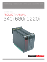
DIN rail release catch
3
Installation

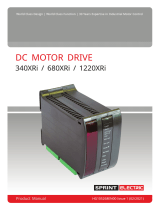
2.2.3
Electrical installation
WARNING!
PERSONAL INJURY AND/OR
EQUIPMENT DAMAGE HAZARD
Never work on any control equipment without rst isolating all power supplies
from the equipment.
Protection must be provided by a correctly rated semi-conductor fuse, tted
upstream of the drive. The fuse must have an I
2
t rating of less than 150 A
2
s at the
applied supply voltage.
8. Wire the plug-in terminal blocks and re-attach to the drive; black-to-black, green-to-
green. DO NOT APPLY POWER AT THIS TIME.
Control cable 1.5 mm
2
External control
options:
Speed setpoint from external 10K potentiometer *
External RUN contact (Terminal 5) for electronic STOP/START
* Potentiometer, graduated dial and knob - Sprint Electric part number: POTKIT
EMC wiring: If the unit is going to be used in the domestic environment, then for
installations in the EU, a supply lter is recommended in order to comply with EN6800-3.
Sprint Electric part number: FRLN16.
2.2.2
Mechanical installation
6. Remove the plug-in terminal blocks
from the bottom of the unit.
7. Clip the drive onto the DIN rail.
• To release the drive from the DIN
rail (with terminal blocks
unplugged), insert a screwdriver
into the slot in the (red) release
catch at the back of the unit and
move the catch downwards.
drive model height/width/depth (mm)
340
105/35/120
340 LV60
680
105/45/120
680 LV60
1220
105/45/120
1220 LV60
FUSE - Class aR Series semiconductor - tted upstream of the drive
To satisfy UL requirements for branch circuit short-circuit protection, the fuse MUST be of
type FWH5-020A6FR (part number CH00620A), or a lower rated fuse from the same series.
drive model drive
rating
fuse
rating
Sprint standard fuses Fuses for UL compliance
340
3.4 A 6.3 A CH0066A3 Bussmann FWH-6.30A6F
340 LV60
680
6.8 A 12.5 A CH00612A Bussmann FWH5-12.5A6FR
680 LV60
1220
12.2 A 20 A CH00620A
Bussmann FWH5-020A6FR
CH00620A
1220 LV60
6 x 32 mm Panel-mount fuse holder - CP102071; DIN rail clip for fuse holder - FE101969
Short Circuit Rating
Suitable for use on a circuit capable of delivering not more than 5000 A RMS Symmetrical
Amperes when protected by a Class aR Series semiconductor fuse.
4
Installation

DANGER!
ELECTRIC
SHOCK
HAZARD
MOTOR
ARMATURE
MOTOR
FIELD
AC SUPPLY
10K
fuse
1
+10
2
MIN
3
I/P
4
COM
5
RUN
6
TACH
A+
A-
F-
F+
N
L
Max spd
Min spd
Ramp
IR comp
I MAX
ON
1 2
Alarm
Avf/Tach
Spd x 2
Power
240/110
110
240
Supply jumper: (LV60 model will indicate 60/30 Vac)
“Fan failure” alarm is active when lit.
Maximum current: rotate clockwise to increase current limit.
0 to 100% current limit.
IR compensation:
rotate clockwise to increase level of armature voltage droop
compensation. 0 to 30%. Excessive rotation may cause instability. Always set
fully anti-clockwise in Tacho mode.
Ramp: Rotate clockwise for a faster response. 20 to 1 seconds up ramp rate.
*
Minimum speed: rotate clockwise to increase minimum speed.
0 to 30% of maximum speed.
Power is present when lit.
Refer to text.
Maximum speed: rotate clockwise to increase speed, 40 V to 200 V
(armature or tach feedback Volts).
LV60 model has Avf range 10 V to 50 V.
ON
1 2
Avf/Tach
Spd x 2
-ve+ve
TG
USER ADJUSTMENTS
ANTI-CLOCKWISE MID-WAY
CLOCKWISE
* Assumes using a 10K
speed reference
potentiometer
(optional)
TERMINAL LISTING - tightening torque: 0.5 Nm (4.4 lbf.in)
1 +10 +10 V output, 2 mA maximum. Use a 10K
potentiometer for external speed reference
A+ * Motor armature +
2 MIN Minimum Speed: connect to minimum
end of internal speed potentiometer 5K preset
to common
A- * Motor armature –
3 IP Speed Input: 0 to +10 V speed input from
the potentiometer wiper. 39K internal pull-
down
F- ** Motor eld –
For half wave eld Volts 0.45 x
AC, connect eld to F– and N.
4 COM Common. 0 V (zero) F+ ** Motor eld +
5 RUN Internal 12K pull-up to 12 V. Close
Terminal 5 to COMMON to run the drive.
See the WARNING below.
N NEUTRAL/RETURN : ac supply
6 TACH When using Tach feedback, the tach
feedback polarity must be negative with
respect to COMMON, Terminal 4
L LIVE : ac supply
*
**
Form factor typically 1.5 (load dependent)
No connection required for permanent magnet motors
WARNING!
PERSONAL INJURY HAZARD
RUN is an electronic inhibit function. The eld remains energised, and all power
terminals ‘live’. During hazardous operations remove the power source to the
system. RUN must not be relied on to ensure the machine is stationary.
The motor FIELD output remains energised with RUN open, please beware of
overheating the motor when stopped (does not apply to permanent magnet
motors).
Earthing: All control inputs to the drive are NON-ISOLATED. Do not connect any of the
terminals to earth or to other non-isolated equipment. A common cause of damage is
accidental earthing of the external potentiometer or RUN contact wiring.
WARNING!
PERSONAL INJURY HAZARD
Terminals A+, A-, F-, F+, N & L are at high potential.
Do not touch the terminals or any connected conductor.
L1/L2/L3, A+/A- Use correctly rated cable - minimum 600 Vac, 1.5 x armature current
5
Installation

3 3
OperationOperation
3.1
Pre-operation motor check list
9. With no power applied, complete the following check list:
• Check for the correct insulation between individual motor elements, and between
these elements and the earthed motor frame. Disconnect all drive cables before
testing. The motor elements are: armature winding, eld winding*, temperature
sensors*, tachogenerator* (* where applicable).
• Check inside the motor connection box for foreign objects, damaged terminals, etc.
• Check that motor brushes are in good condition, correctly seated and free to move in
brush boxes. Check for the correct action of brush springs.
• Check that motor vents are free of any obstruction and that any protective covers
have been removed.
3.2
Operating the drive
REFER TO THE WARNING ON PAGE 7.
WARNING!
PERSONAL INJURY HAZARD
This product is non-isolated and so, when power is applied to the drive, ALL
terminals are at dangerous line potential.
Ensure that connected items (e.g. speed potentiometer, Tacho etc.) are NOT
earthed, and have sucient dielectric strength to avoid breakdown.
10. For this initial start, disconnect and insulate the (optional) Tacho connection to
Terminal 6 as the drive will be using Armature Voltage feedback.
11. Apply power to the drive. The drive's Power lamp will light.
12. Operate the RUN switch to turn the motor.
13. Slowly increase the external speed potentiometer setting to maximum. The motor will
ramp up slowly to about 40 V on the motor armature (to about 10 V for LV60 units).
14. Is the motor turning in the required direction? If not, reverse the system by
transposing the A+ and A- motor armature connections.
CAUTION!
When reversing the system: To prevent damage, do not transpose the
motor armature connections until the motor has stopped rotating.
6
Operation

WARNING!
PERSONAL INJURY AND/OR
EQUIPMENT DAMAGE HAZARD
If you change the Spd x 2 switch position while running, the speed will
undergo an immediate step change.
a. Set the Spd x 2 switch to suit the motor armature voltage rating:
340 / 680 / 1220
OFF: 40 to 100 V armature voltage range
ON: 90 to 200 V armature voltage range
340 LV60 / 680 LV60 / 1220 LV60
OFF: 10 to 25 V armature voltage range
ON: 23 to 50 V armature voltage range
b. Adjust the Max spd potentiometer setting to achieve the required shaft speed.
16. MIN SPEED: The Min spd potentiometer can now adjust between 0% and 30%. (This
assumes that a 10K potentiometer is being used to provide the speed setpoint at
terminal 1, 2 and 3.)
17. RAMP: Set the ramp up rate as required (from 20 seconds to 1 second).
The drive is now commisioned to use Armature Voltage feedback.
15. Speed Feedback selection Set the correct Armature Voltage using the Spd x 2 switch
and the Max spd preset:
18. IR COMP: Speed droop on heavy loads may occur where armature voltage feedback
is used. Compensate for this by clockwise adjustment of the IR comp preset. Excessive
rotation may lead to instability.
7
Operation

4 4
OptionsOptions
• Speed Feedback selection: If the system is to use Tacho feedback you can now adjust
for the tachogenerator's output voltage, and hence the speed of the motor:
Run the drive in Armature Voltage feedback mode and check the polarity of the
tacho using a voltmeter. The tacho feedback polarity must be negative with respect to
COMMON, Terminal 4.
REFER TO THE WARNING ON PAGE 7.
NOTE: IR COMP must not be used with Tacho feedback - set the potentiometer
fully anti-clockwise.
a. With the power off, connect the tachogenerator's output voltage to Terminal 6.
Set the Avf/Tach switch to OFF (right).
Calculate the output voltage from the tachogenerator:
For example, if quoted as "100 V per 1000 revs/min" then feedback voltage =
(motor speed/1000) x 100 V
b. Set the Spd x 2 switch to suit the calculated feedback voltage
(refer to the switch ranges given for Armature Voltage).
c. With the drive running, adjust the Max spd preset to achieve the required shaft
speed.
DANGER!
ELECTRIC
SHOCK
HAZARD
MOTOR
ARMATURE
MOTOR
FIELD
AC SUPPLY
10K
fuse
1
+10
2
MIN
3
I/P
4
COM
5
RUN
6
TACH
A+
A-
F-
F+
N
L
Max spd
Min spd
Ramp
IR comp
I MAX
ON
1 2
Alarm
Avf/Tach
Spd x 2
Power
240/110
110
240
Supply jumper: (LV60 model will indicate 60/30 Vac)
“Fan failure” alarm is active when lit.
Maximum current: rotate clockwise to increase current limit.
0 to 100% current limit.
IR compensation:
rotate clockwise to increase level of armature voltage droop
compensation. 0 to 30%. Excessive rotation may cause instability. Always set
fully anti-clockwise in Tacho mode.
Ramp: Rotate clockwise for a faster response. 20 to 1 seconds up ramp rate.
*
Minimum speed: rotate clockwise to increase minimum speed.
0 to 30% of maximum speed.
Power is present when lit.
Refer to text.
Maximum speed: rotate clockwise to increase speed, 40 V to 200 V
(armature or tach feedback Volts).
LV60 model has Avf range 10 V to 50 V.
ON
1 2
Avf/Tach
Spd x 2
-ve+ve
TG
USER ADJUSTMENTS
ANTI-CLOCKWISE MID-WAY
CLOCKWISE
* Assumes using a 10K
speed reference
potentiometer
(optional)
• Jogging We recommend using the RUN input (Terminal 5) for stopping or jogging. If you
use a mains contactor, connect a spare normally-open contact of the contactor in series
with the RUN input.
• Auxiliary input: If the system is using Armature Voltage feedback, then Terminal 6
(TACH) may be used as an auxiliary fast ± speed trim (approximately 5-10%).
• Alarms:
WARNING!
PERSONAL INJURY HAZARD
The following alarm provides an electronic armature current inhibit function.
The eld output remains energised and
all power terminals are LIVE (shock hazard),
hence these terminals must not be relied upon to ensure the machine is
stationary during hazardous operations.
The motor FIELD output remains energised; please beware of overheating the
motor when stopped - this does not apply to permanent magnet motors.
• "Fan Failure" Alarm: Models 680 and 1220 use an internal fan for cooling. The
Alarm lamp will light if the internal fan fails - the drive will electronically shut down.
These units may be run at currents below 3 A without a fan.
To inhibit the Alarm, link the pair of solder pads adjacent to Terminal 6 (TACH).
8
Options

5 5
SpecicationsSpecications
All specications in this document are nominal.
This product conforms to IP00 protection.
RATINGS
drive model AC supply
input
1 ph 50-60 Hz
maximum output power
rating
armature voltage armature
current
eld
current **
(Vac ±10%) (Vdc) (Adc) (Adc max) (kW / hp)
340
340 LV60
110 or 240
30 or 60
90–180 (200 V max)
24–48 (50 V max)
3.4
3.4
1
1
0.55 / 0.75
*
680
680 LV60
110 or 240
30 or 60
90–180 (200 V max)
24–48 (50 V max)
6.8
6.8
1
1
0.75 / 1
*
1220
1220 LV60
110 or 240
30 or 60
90–180 (200 V max)
24–48 (50 V max)
12.2
12.2
1
1
1.8 / 2
*
kW / hp ratings are for typical motor ratings at or below the available terminal ratings of
Watts = armature Volts x armature Amps.
*
Note that the power output of LV60 versions will be proportionately lower than is shown above.
**
Volts DC = 0.9 x AC supply Volts (0.45 x AC supply Volts for eld connected to F- and N)
A+ / A- motor armature terminals have Form Factor typically 1.5 (load dependent).
Disposal
This product contains materials that are consignable waste under the Hazardous Waste
Regulations 2005. Metal and plastic materials can be recycled, however, disposal of the
printed circuit board requires compliance with all valid environmental control laws.
Products that must be recycled in accordance with the WEEE Regulations are
marked with the symbol opposite. Contact us when recyling the product.
9
Specications


©2021, Sprint Electric. All rights reserved.
We accept no liability whatsoever for the installation,
fi tness for purpose or application of this product.
It is the user’s responsibility to ensure the unit is
correctly used and installed.
This leafl et is protected by copyright. No part of it may
be stored or reproduced in any form without written
permission from Sprint Electric.
The information in this publication was correct at the
time of going to print.
We reserve the right to modify or improve the product
without notifi cation.
The contents of this manual shall not become part of
or modify any prior existing agreement, commitment,
or relationship. The sales contract contains the entire
obligation of Sprint Electric. The warranty contained in
the contract between the parties is the sole warranty of
Sprint Electric. Any statements contained herein do not
create new warranties or modify the existing warranty.
We will be under no liability for any defect arising from
fair wear and tear, negligence, wilful damage, misuse,
abnormal working conditions, failure to follow the
manufacturer’s instructions, unauthorised alteration or
repair of hardware, unauthorised or accidental alteration
of software or confi guration, lost profi ts, commercial
loss, economic loss, or loss arising from personal injury.
We may, at our discretion, raise a charge for any faults
repaired that fall outside the warranty cover.
Sprint Electric Limited, Peregrine House, Ford Lane, Ford, Arundel BN18 0DF, U.K.
Tel: +44 (0)1243 558080 Fax:+44 (0)1243 558099 Email: [email protected]
www.sprint-electric.com
/