Page is loading ...

Elite, Deluxe &
Deluxe Plus
Window Awnings
With
830657.300(X) Standard, 831657.300(X) Large
832657.300(X) Standard Monochromatic,
833657.300(X) Large Monochromatic
Hardware Installation
INSTALLATION & OPERATING
INSTRUCTIONS
MODEL
830657.300(X)
831657.300(X)
832657.300(X)
833657.300(X)
REVISION A
Form 3308242.019 02/17
(French 3308255.003_A)
©2017 Dometic Corporation
LaGrange, IN 46761
This manual must be read and
understood before installation, ad-
justment, service, or maintenance
is performed. This unit must be
installed by a qualied service tech-
nician. Modication of this product
can be extremely hazardous and
could result in personal injury or
property damage.
Lire et comprendre ce manuel avant
de procéder à l'installation, à des
réglages, de l'entretien ou des répa-
rations. L'installation de cet appareil
doit être effectuée par un réparateur
qualié. Toute modication de cet
appareil peut être extrêmement dan-
gereuse et entraîner des blessures
ou dommages matériels.
USA
SERVICE OFFICE
Dometic Corporation
1120 North Main Street
Elkhart, IN 46516
CANADA
Dometic Corporation
46 Zatonski, Unit 3
Brantford, ON N3T 5L8
CANADA
SERVICE CENTER &
DEALER LOCATIONS
Visit:
www.eDometic.com

2
Elite, Deluxe & Deluxe Plus Window Awning Installation & Operating Instructions
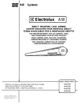
AWNING RAIL
DOOR FRAME
#6-20 X 1/2 PHP.
PAN HEAD
SHEET METAL
SCREWS
APPROXIMATELY
5"
CAULKING
COMPOUND
FIG. 1
GENERAL INFORMATION
Application:
The Dometic Corporation Window Awning is designed for
use on recreational vehicles and is available in a variety
of sizes.
Fabric Roller Tube Assembly (FRTA) Hardware
(*) Awning Rail (730099-B)
(*) Window Strap Hanger (3107025.003(X)
(*) #10-12 x 3/4" Sheet Metal Screw (3105445.005
(*) 3/16" x 1" Oscar Rivet (113008)
(*) 1/8" x 1/4" Alum Pop Rivet (308171.026)
* Quantity varies depending on model number
Hardware Assembly Hardware
(2) 1/4"-20 x 3/4" Php. Truss Head Screw (113142.003)
(8) #10-12 x 3/4" Php. Pan Head (3105445.005)
(8) 3/16" x 1" Oscar Rivet (113008)
(30) #6-20 x 1/2" Pan Head (3107216.008)
(2) #6-20 x .44" Hex Self Drilling Screw (310359.012)
Important: Read all of the following steps before
beginning installation.
Dometic Corporation reserves the right to modify appear-
ances and specications without notice.
INSTALLATION INSTRUCTIONS
Do not remove cotter pins at this time. The
FRTA is pre-wound and under tension. Rapid
spin-off will occur if the cotter pins are re-
moved. Failure to follow these instructions
could cause serious personal injury or prop-
erty damage.
1. Install the Awning Rail
Position and center awning rail approximately 5" above
the top of the window. See FIG. 1.
Apply a caulking compound behind the awning rail before
securing rail with #6-20 x 1/2" sheet metal screws. See
FIG. 1.
SAFETY INSTRUCTIONS
This manual has safety information and instruc-
tions to help users eliminate or reduce the risk of
accidents and injuries.
RECOGNIZE SAFETY INFORMATION
This is the safety-alert symbol. When you see
this symbol in this manual, be alert to the poten-
tial for personal injury.
Follow recommended precautions and safe op-
erating instructions.
UNDERSTAND SIGNAL WORDS
A signal word , WARNING OR CAUTION is used
with the safety-alert symbol. They give the level
of risk for potential injury.
indicates a potentially hazard-
ous situation which, if not avoided, could result
in death or serious injury.
indicates a potentially hazard-
ous situation which, if not avoided, may result in
minor or moderate injury.
CAUTION
used without the safety alert
symbol indicates, a potentially hazardous situa-
tion which, if not avoided, may result in property
damage.
Read and follow all safety information and in-
structions.

3
Elite, Deluxe & Deluxe Plus Window Awning Installation & Operating Instructions
Mark location of bottom mounting bracket holes.
For wood structure, drill four 1/8" dia. holes and secure
bottom bracket using four (4) #10-12 x 3/4" sheet metal
screws. Apply caulking compound to screws before in-
serting.
If only the skin of the RV is to be used, use a #5 drill bit,
and secure the bottom mounting bracket using 3/16" x 1"
Oscar Rivets. Apply caulking compound to rivets. Repeat
for other side.
4. Releasing Preset Tension
Note: Dometic Corporation window awning torsions are
pre-wound at the factory.
Remove cotter pin that is holding factory pre-set tension.
The cotter pin is found in the roller tube end cap. See FIG.
4. For easier removal, twist the roller tube as if unrolling
awning while pulling on cotter pin.
If for some reason the torsion tension has been released,
it can be re-wound after the awning is completely installed.
See page 4 for winding instructions.
FABRIC ROLLER
TUBE ASSEMBLY
1/4"-20 X 3/4"
PHP. TRUSS
HD. BOLT
MAIN ARM
FIG. 2A
TOP CASTING
FIG. 2B
RUBBER SEAL
METAL HINGE
AWNING RAIL
TOP SLAT
2. Hang the Awning
Remove tape used for shipping.
Secure the arms to the top casting with 1/4"-20 x 3/4"
bolts. (Arms are identical) See FIG. 2A.
Important: Unroll enough fabric to slide bead into
awning rail. If too much fabric is unrolled before releas-
ing the preset tension, there will NOT be the required
amount of tension to sufciently roll the awning back
up after use.
Insert hinge or fabric of FRTA into the awning rail, lift rub-
ber seal over top of the awning rail, slide entire window
awning into awning rail. See FIG. 2B & 2C.
3. Install Bottom Mounting Bracket
Important: Position the bottom mounting bracket so
the top of the end cap is level with the opening of the
awning rail. This insures the awning shield wraps up
tightly. FIG. 3A.
FIG. 2C
AWNING RAIL
FIG. 3A
FIG. 4
COTTER PIN
END CAP
When cotter pins are removed, springs are
under tension. The awning will attempt to
close. Keep body and clothing clear of hard-
ware and roller tube.

4
Elite, Deluxe & Deluxe Plus Window Awning Installation & Operating Instructions
Discard pin and repeat for other side.
The awning should now roll up snugly against the vehicle
side. If it does not, check to see that the springs have
been wound properly. See page 4.
Use extreme care. Springs under tension are
dangerous. If not controlled they will unwind
quickly. Keep body and clothing clear of
top castings, as personal injury may result.
5. Installation of Window Strap Hanger
After fabric roller tube assembly is mounted on the RV,
open the awning to its full extension by pulling down on
the pull strap.
Center the strap in the awning, then move the loop of
the pull strap toward the RV and under the window sill
to locate the placement of the window strap hanger. See
FIG. 5A.
Locate the strap hanger so that the top loop of the strap is
engaged onto the hanger, thus allowing for minor height
adjustment of the awning. See FIG. 5B.
Important: Make sure awning is pulled taut by the
pull strap when positioning the strap hanger.
Mark location.
Install strap hanger with three (3) #10-12 x 3/4" Pan Hd.
Sheet Metal Screws or 3/16" x 1" Oscar Rivets as need-
ed. Apply caulking compound to screws or rivets before
inserting.
Center window awning.
For awnings with metal weather shield, install #6-20 x .44"
self-drilling screws into the awning rail immediately next
to the metal hinge. Repeat on other side. See FIG. 5C.
For awnings with fabric weather shield, install #6-20 x
.44" self-drilling screws into the awning rail 2" from end of
fabric. See FIG. 5C.
PULL
STRAP
AWNING
STRAP
HANGER
LOCATION
FIG. 5A
FIG. 6A
MAIN
ARM
AWNING
STRAP
HANGER
PULL STRAP
TOP LOOP
FIG. 5B
.44" SCREW
FIG. 5C
AWNING RAIL
2"
OPERATING INSTRUCTIONS
To Open Awning
1. Pull strap down to extend awning then hook the loop
onto the hanger. See FIG. 6A & 6B.
HANGER
HANGER
AWNING
PULL STRAP
PULL
STRAP
LOOP
FIG. 6B
To Close Awning
1. Remove pull strap from hanger. See FIG. 6B.
Do not release strap as window awning is
under tension and may snap back against
vehicle.
2. Slowly allow awning to close by feeding pull strap up-
wards and diagonally. This prevents the strap from build-
ing up and creating a bulge in the fabric. See FIG. 6A.
3. The awning Installation is now complete and ready for
travel.

5
Elite, Deluxe & Deluxe Plus Window Awning Installation & Operating Instructions
WINDING TORSIONS
Important: Winding torsions is not part of the normal
installation procedure for this awning. The following
procedure is only done if the torsion tension has been
released.
Use extreme care. Springs under tension
are dangerous. If not controlled they will
unwind quickly. Keep hands and clothing
clear of top casting, as personal injury may
result.
Wind The Torsion
1. Torsions are to be wound with the awning in the near
closed position. Open awning just far enough to be able
to rotate the top casting on FRTA (approximately 2").
2. Remove the bolt and lift the top casting out of the
arm.
3. Turn the top casting the number of turns specied in
the awning size chart, and carefully insert it back into
the arm. Reinstall the bolt. Repeat for other side. See
FIG. 7A.
Note: When facing the awning, the top casting on the
RIGHT is to be turned COUNTER-CLOCKWISE. See FIG.
7B. The top casting on the left is to be turned CLOCK-
WISE. See FIG. 7C.
Awning:
30"-48" 54" 60" 66"-84"
Turns:
9 10 11 12
Awning:
90"-123" 126"-144" 156"-192"
Turns:
13 14 16
FIG. 7A
TOP CASTING
FABRIC ROLLER
TUBE ASSEMBLY
MAIN SUPPORT ARM
FIG. 7B
FIG. 7C
RIGHT END CAP
LEFT END CAP
END CAP VIEWED
FROM RIGHT SIDE
END CAP VIEWED
FROM LEFT SIDE
/