Page is loading ...

USA
SERVICE OFFICE
Dometic Corporation
1120 North Main Street
Elkhart, IN 46514
CANADA
Dometic Corporation
46 Zatonski, Unit 3
Brantford, ON N3T 5L8
CANADA
SERVICE CENTER &
DEALER LOCATIONS
Please Visit:
www.eDometic.com
INSTALLATION
INSTRUCTIONS
This manual must be read and
understood before installation, ad-
justment, service, or maintenance
is performed. This unit must be
installed by a qualied service tech-
nician. Modication of this product
can be extremely hazardous and
could result in personal injury or
property damage.
WeatherPro Hardware
855(X)004.40(X)(X) 5th Wheel Standard Hardware
FOR
8(X)5(XX)(XX.XX)(X)(X)
Fabric Roller Tube Assembly
REVISION A
Form No. 3308192.016 10/16
©2016 Dometic Corporation
LaGrange, IN 46761
Important: These instructions must stay with unit.
Owner read carefully.
Lire et comprendre ce manuel avant
de procéder à l'installation, à des
réglages, de l'entretien ou des répa-
rations. L'installation de cet appareil
doit être effectuée par un réparateur
qualié. Toute modication de cet
appareil peut être extrêmement dan-
gereuse et entraîner des blessures ou
dommages matériels.
MODEL
8(X)5(XX)(XX.XX)(X)(X)FRTA
855(X)004.40(X)(X)
Hardware

2
GENERAL INFORMATION
COVERED BY PATENT 5383346, 4941524, D366763,
6095221, 6230783, D414880, 6164883, 6276424,
6230786, D410192,D429894 & 6273172
OTHER PATENTS PENDING
REQUIRED PARTS (Packed with each Hardware Assembly)
8553004.40(X)(X) & 8554004.40(X)(X) Hardware
(2) Bottom Bracket Cover (3109752.000(X)
(4) #14-10 x 1-1/2" Hex Head Screw (3104499.003)
(4) #14-10 x 2" Hex Head Screw (3104499.086)
(2) .25" Split Lock Washer (3101746.000)
(4) #10-16 x 3/4" Hex Washer Head Self Drilling Screw
(310359.013)
(4) 3/16" x 1" Oscar Rivets (113008)
(2) #6-20 x .44" Hex Washer Head Self Drilling Screw (310359.012)
(2) 1/4"- 20 x 3/4" Hex Head Bolts (3104176.205)
(2) Spacer (3307943.005(X)
(1) Cover, Travel Lock Wire (3109577.019(X)
Important: Read and understand ALL of the follow-
ing steps before beginning installation.
Application
The Dometic Corporation awning is designed and intended
for use on Motorhomes, Travel Trailers, and Fifth Wheels
with straight sides.
Important: Structural backing is required where
mounting screws will be installed through sidewall for
securing top mounting brackets and back channels.
Important: Follow the Minimum distance dimen-
sions requirements from awning rail to door. Mounting
height depends on awning type and length. Insure
sufcient room is available before starting installa-
tion. If questions arise, contact your Dometic Sales
Representative.
Hardware Model Metal Weather Shield
8553004.40(X)(X) 12"
8554004.40(X)(X) 12"
When the door falls in the center of the awning, add 2" to
these distances.
Installation Height: This is the center to center distance
of mounting holes in the top mounting bracket and the
back channel. See Specication chart and illustrations
on page 3.
Dometic Corporation reserves the right to modify ap-
pearances and specications without notice.
SAFETY INSTRUCTIONS
This manual has safety information and instruc-
tions to help users eliminate or reduce the risk
of accidents and injuries.
RECOGNIZE SAFETY INFORMATION
This is the safety-alert symbol. When you see
this symbol in this manual, be alert to the po-
tential for personal injury.
Follow recommended precautions and safe
operating instructions.
UNDERSTAND SIGNAL WORDS
A signal word , WARNING OR CAUTION is used
with the safety-alert symbol. They give the level
of risk for potential injury.
indicates a potentially hazard-
ous situation which, if not avoided, could result
in death or serious injury.
indicates a potentially hazard-
ous situation which, if not avoided, may result in
minor or moderate injury.
used without the safety alert
symbol indicates, a potentially hazardous situa-
tion which, if not avoided, may result in property
damage.
Read and follow all safety information and
instructions.

3
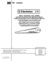
A = Overall length of hardware
B = Minimum mounting distance center to center on mounting
holes.
C = Maximum mounting distance center to center on mounting
holes.
D = Distance between mounting holes in bracket.
E = Location of hole for wire harness.
F = Back channel length.
G = Distance between bottom of back channel and center of
mounting hole.
H = Distance front channel guard extends past back channel.
J = Distance from top edge of top bracket and center of rst
mounting hole.
855(X)004.40(X)(X) 5th Wheel Hardware
A
B
E - F
C
D
J
G
H
Top Mounting Bracket
Front
Channel
Hole For
Cable
Front Channel
Cover
Back
Channel
FIG. 1
Installation Instructions
1. Secure FRTA to Hardware
A. Carefully lay the fabric roller tube assembly on a
clean, well padded "V" trough to prevent fabric
and/or roller cover damage. Remove the hardware
from the packaging and place the motorized arm on
the right side. The non-motorized arm has a spring
loaded bottom arm and goes on the left side.
Do not remove the cotter pin located on the
left end of the FRTA until instructed to do so.
The FRTA is pre-wound and under tension.
Rapid spin-off will occur if the cotter pin is
removed.
Do not remove the nylon ties until instructed
to do so. The hardware arm assemblies are
pressurized and will spring open.
Failure to follow these instructions could
cause serious personal injury or property
damage.
B. Secure each front channel to top casting mounted
at the end of the FRTA. See FIG. 2. Slide top nylon
tie down arm approximately 24 inches to allow hard-
ware to open far enough to insert top casting into
channel. Do Not remove nylon ties at this time. Arm
assemblies are pressurized and will spring open.
Note: One hardware arm assembly is pre-wired for mo-
tor. This arm goes on the right side.
Installation of Dometic Corporation awnings will briey
require three people. Use the following procedure to as-
sure a properly installed, and properly functioning awning.
FIG. 2
Bolt, Spacer
& Lock Washer
Front
Channel
Top
Casting
Nylon Tie
Back
Channel
Specication Chart
855(X)004.40(X)(X)
A 67-1/4"
B 63-11/64"
C 63-15/16"
D 3/4"
E 65-1/2"
F 65-1/2"
G 1-5/32"
H 1-3/4"
J 13/32"
Note: One hardware arm assembly has a spring loaded
bottom arm. This arm goes on left side. See FIG. 3.

4
C. Using one (1) 1/4"-20 x 3/4" hex head bolt, one spacer
and one (1) .25 split lock washer secure both top
castings to front channels. See FIG. 2.
D. Remove cotter pin from LH end cap.
Do not attempt to separate the FRTA from
the hardware arm unless the torsion assem-
blies are re-pinned. The FRTA is pre-wound
and under tension. Rapid spin-off will occur
if separated. Failure to follow these instruc-
tions could cause serious personal injury or
property damage.
2. Install Fabric in Awning Rail
A. Prepare the awning rail to accept the awning fabric.
Select the end from which the awning shall be fed,
then widen that end with a at screwdriver and le
off any sharp edges. See FIG. 4A.
B. Unwind fabric one revolution before feeding awning
fabric into awning rail. This will allow enough space
between side wall and awning hardware to connect
wires in Step 3-D-1.
C. With one person grasping each arm assembly, care-
fully lift the entire assembly to an upright position.
Important: Keep the two arm assemblies parallel to
each other to avoid excessive twisting and possible
damage to the assembly.
Walk the awning to the end where the awning rail
was prepared. See FIG. 4B.
FIG. 3
Spring Loaded Bottom Arm
Pin &
Roto Clip
Back
Channel
BEFORE
AFTER
FIG. 4B
ARM
ASM.
AWNING
RAIL
FABRIC ROLLER
TUBE ASSEMBLY
NYLON
TIE
FIG. 4A
NYLON
TIE
A third person is now required to feed the fabric into
the awning rail. The other two will walk the entire
awning assembly forward and into the desired posi-
tion.
3. Top Mounting Bracket Installation
A. After the complete awning assembly has been
threaded into the awning rail, check that its posi-
tion allows for solid mounting of the top mounting
brackets and the back channels. Also insure that
the back channels are in the desired location (not
restricting use of doors, access doors, windows,
etc.).
Important: Structural backing is required where
mounting screws will be installed through sidewall for
securing top mounting brackets.
Note: Awning rails with rain gutters may not allow the FRTA
to close all the way. It may be necessary to lower the top
bracket position to ensure the FRTA will close properly.
B. On the motorized arm assembly (right side),
place the top bracket in position directly under
the awning rail as shown in FIG. 5B.
Top bracket must be installed level with the awning
rail. Using the outside bracket hole as a guide
pre- drill a 3/16" hole for mounting screw. Drill a
7/32" hole if drilling into steel. Install outside top
mounting bracket using one (1) #14-10 x 1-1/2"
hex head screw. Seal where the screw enters
the side wall with clear silicon sealer. Repeat this
procedure for opposite side.
+
+
+
+
+
+
Top
Bracket
Bolt,
Spacer &
Lock Washer
Front
Channel
FIG. 5A
FIG. 5B
Top
Bracket

5
C. To install screws on the inside top mounting
brackets it will be necessary to pull the FRTA away
from the side wall approximately 12". Remove
nylon ties wrapped around the front and back
channels. See FIG. 2. Grasp the front channel and
slowly pull it away from the sidewall. See FIG. 6.
Pre-drill hole as in previous step and install one
(1) #14-10 x 1-1/2" hex head screw. Repeat this
procedure for opposite side. Seal where screw
enters the side wall with clear silicon sealer.
Do not attempt to separate the FRTA from
the hardware arm unless torsion assembly
is re-pinned and the arm assemblies are re-
tied. The FRTA is pre-wound and under ten-
sion. Rapid spin-off will occur if separated.
The arm assemblies are pressurized and will
spring open. Failure to follow these instruc-
tions could cause serious personal injury or
property damage.
D. Motor connection
1. Connect the motor wire to the factory pre-wired
hardware wiring. See FIG. 6.
2. Install wire cover in back of front channel to
secure wires. This cover is pressure tted.
Slightly squeeze sides to insert into channel.
Be careful not to over squeeze. This could
reduce the tension causing the cover to be
loose.
Important: Dielectric grease must be placed on all
exposed pins.
FIG. 6
4. 3307844.004 Control Box Kit and Remote Switch
Installation. See individual installation instruc-
tions packaged with kit.)
Important: Electronic control box is also pre-wired
for installing an Oasis Elite awning. Use only wires
designated for WeatherPro.
Important: Each control kit contains one (1) Key
Fob (Remote Control) and it must stay with awning
for end user.
Note: Awning is not intended for cold weather opera-
tion. Awning will close at approximately 30 degrees F. with
sensor turned on.
Note: The awning control box contains an audible alarm.
This alarm will sound if the wind sensor is exposed to tem-
peratures 30 degrees or below when the sensor switch
is on or when the awning control has detected a prob-
lem either in the wind sensor or the wind sensor cable.
If you hear a beeping sound coming from the control box
when the sensor switch is in the "ENABLE" (ON) position
one of the above situations has occured. When the alarm
sounds the wind sensor feature is not functioning. Turn
the sensor switch to the "DISABLE" (OFF) position and
wait till the ambient temperature is above 30 degrees F.
and turn switch back on. If alarm is still sounding contact
a Dometic Service Center or a qualied service technician
for assistance.
Motor
Arm
The arm assemblies must be controlled
while the top mounting brackets are being
installed. When the weight of the FRTA is no
longer supported, the downward force could
cause the arm assembly to swing side ways
and may damage the sidewall if not con-
trolled.

6
6
Align Square
Bottom Bracket
Screw Cover
Bottom Bracket
Oscar Rivets
Bottom Bracket
Screw
Floor Line
6. Initial Awning Adjustment
A. Cycle the awning four or ve times to check fabric
alignment and to make sure the hardware is nest-
ing properly. If there is a misalignment, adjust the arm
by loosening the upper mounting bolts and move
the bracket accordingly. Cycle the awning again to
check the alignment. See User's Guide for opening
and closing instructions.
B. When satised with the alignment, secure fabric
roller cover by driving a # 6-20 x .44" Tek screw
through the rail and into the fabric rope. See FIG.
8 for screw location. Repeat at opposite end. Snap
bottom screw cover in position. See FIG. 7. The
installation is now complete and ready for use.
5. Back Channel And Bottom Bracket Installa-
tion
Important: Structural backing (metal) is required
where oscar rivets will be installed through sidewall
for securing back channels.
A. Securing Back Channels
1. Open awning as required to secure back channel
and install bottom bracket.
2. Remove bottom bracket from inside back channel
if installed.
3. Align the back channel so it is square with the
vehicle and the FRTA. A door or window frame
can be used to measure from. See FIG.7.
FIG. 7
4. Drill two (2) 3/16" holes through the outside wall
using the holes in the bottom of back channel as
a guide. See FIG. 1.
5. Secure back channel to wall with two (2)
3/16" x 1" Oscar rivets provided. Be careful
not to pinch or damage motor wire when securing
channel to wall. See FIG 7.
Important: Structural backing (metal) is required
where oscar rivets will be installed through sidewall
for securing back channel.
6. Seal where the oscar rivets enter the vehicle with
clear silicon sealer.
7. Slide bottom brackets back into position. While
holding bottom bracket in position drive two (2)
# 10-16 x 3/4" self drilling screws through hole
in back channel and into bracket. See FIG. 7.
7. Close and Secure Awning
A. If awning will not be used after installation, close and
secure. See User's Guide for closing and securing
instructions.
FIG. 8
/