Page is loading ...

Read these instructions carefully. These
instructions MUST stay with this product.
USA
SERVICE OFFICE
Dometic Corporation
1120 North Main Street
Elkhart, IN 46514
CANADA
Dometic Corporation
46 Zatonski, Unit 3
Brantford, ON N3T 5L8
CANADA
SERVICE CENTER &
DEALER LOCATIONS
Please Visit:
www.eDometic.com
REVISION B
Form No. 3105903.060 01/17
(French 3108577.044_B)
©2017 Dometic Corporation
LaGrange, IN 46761
RECORD THIS INFORMATION FOR FUTURE
REFERENCE:
FRTA Model Number
FRTA Serial Number
Hardware Model Number
Hardware Serial Number
Date Purchased
Retailer / Qualied Installer
8300™,
SUNCHASER
®
FABRIC ROLLER TUBE ASSEMBLY
(FRTA)
REPLACEMENT INSTRUCTIONS
■ FABRIC ■ ROLLER TUBE ■ TORSION ASSEMBLY
MODEL
828XXXX, 830XXXX, 833XXXX,
834XXXX, 836XXXX SERIES
SERVICE
INSTRUCTIONS

2
TABLE OF CONTENTS
INTRODUCTION ....................................................................................................................................................................2
DOCUMENT SYMBOLS ........................................................................................................................................................2
IMPORTANT SAFETY INSTRUCTIONS ................................................................................................................................ 3
A. Recognize Safety Information ...................................................................................................................................3
B. Understand Signal Words ..........................................................................................................................................3
C. Supplemental Directives ............................................................................................................................................ 3
D. General Safety Messages .........................................................................................................................................3
GENERAL INFORMATION .....................................................................................................................................................3
A. Required Kits .............................................................................................................................................................3
PREPARE AWNING ...............................................................................................................................................................4
A. Stage Awning For All Procedures ..............................................................................................................................4
B. Prepare For Awning Removal ....................................................................................................................................4
C. Detach Arm Assemblies .............................................................................................................................................4
D. Remove Awning From RV .........................................................................................................................................5
E. Pin Torsions ...............................................................................................................................................................5
REMOVE TORSION(S) ..........................................................................................................................................................6
A. Unwind Torsion(s) ...................................................................................................................................................... 6
B. Remove OLD Torsion(s) ............................................................................................................................................7
REPLACE AWNING FABRIC / FABRIC ROLLER TUBE .......................................................................................................8
A. Prepare Work Area ....................................................................................................................................................8
B. Remove Awning Fabric / Fabric Roller Tube .............................................................................................................8
C. Prepare New Awning Fabric ......................................................................................................................................8
D. Install Awning Fabric / Fabric Roller Tube .................................................................................................................8
REPLACE TORSION(S) ......................................................................................................................................................... 9
A. Prepare Awning Fabric For Torsion(s) .......................................................................................................................9
B. Install Torsion(s) ........................................................................................................................................................9
WIND TORSION(S) .............................................................................................................................................................. 11
REATTACH TORSION(S) TO AWNING HARDWARE .........................................................................................................14
A. Attach Torsion To Hardware ....................................................................................................................................14
B. Remove Nails ..........................................................................................................................................................14
FINISH INSTALLATION ........................................................................................................................................................15
VERIFY INSTALLATION.......................................................................................................................................................15
A. Test Operation .........................................................................................................................................................15
B. Secure Awning For Travel .......................................................................................................................................15
C. Keep Literature ........................................................................................................................................................15
INTRODUCTION
These instructions apply to manual type patio awnings (hereinafter referred to as “awning”, or “product”). The Fabric Roller
Tube Assembly (hereinafter referred to as “FRTA”) consists of a vinyl or acrylic fabric, fabric roller tube, and two torsion as-
semblies.
Read these instructions and highlight the appropriate steps for your particular procedure BEFORE starting the
replacement. Replacements can be performed by one person with brief help from additional personnel. Use these instruc-
tions to ensure correct installation, function, and operation of product.
Dometic Corporation reserves the right to modify appearances and specications without notice.
DOCUMENT SYMBOLS
Indicates additional information that is NOT related
to physical injury.
Indicates step-by-step instructions.

3
The installation MUST comply with all ap-
plicable local and national codes, including
the latest edition of the following standards:
U.S.A.
● ANSI/NFPA70, National Electrical Code
(NEC)
● ANSI/NFPA 1192, Recreational Vehicles
Code
CANADA
● CSA C22.1, Parts l & ll, Canadian Electri-
cal Code
● CSA Z240 RV Series, Recreational
Vehicles
D. General Safety Messages
Failure to obey the following warn-
ings could result in death or serious injury:
● This product MUST be [installed / serviced] by a
qualied service technician.
● Do NOT modify this product beyond the scope of
these service instructions. Modication (beyond
these service instructions) can be extremely
hazardous.
● IMPACT OR CRUSH HAZARD. This product
should be installed in a controlled environment
(inside). Do NOT install product during windy
conditions, or when wind is expected. Otherwise,
product could move unpredictably, become un-
stable, and could [detach / bend / collapse].
This manual has safety information and instructions to help
you eliminate or reduce the risk of accidents and injuries.
A. Recognize Safety Information
This is the safety alert symbol. It is used to
alert you to potential physical injury hazards.
Obey all safety messages that follow this
symbol to avoid possible injury or death.
B. Understand Signal Words
A signal word will identify safety messages and
property damage messages, and will indicate the
degree or level of hazard seriousness.
indicates a hazardous situation that,
if NOT avoided, could result in death or serious in-
jury.
indicates a hazardous situation that,
if NOT avoided, could result in minor or moderate
injury.
is used to address practices NOT
related to physical injury.
C. Supplemental Directives
Read and follow all safety information and
instructions to avoid possible injury or death.
Read and understand these instructions be-
fore [installing / using / servicing / performing
maintenance on] this product.
Incorrect [installation / operation / servicing /
maintaining] of this product can lead to seri-
ous injury. Follow all instructions.
IMPORTANT SAFETY INSTRUCTIONS
GENERAL INFORMATION
A. Required Kits
● Fabric, fabric roller tube, and torsion replace-
ment:
(1) 3308334.006U Torsion Crank Assembly
● Fabric and fabric roller tube replacement
(1) 3109976.005 (End Cap) Fabric Guide

4
A. Stage Awning For All Procedures
With awning safety lock in roll down position, open
(extend) awning two revolutions (turns) of FRTA.
See (FIG. 1).
See “Opening Awning” in Operating Instruc-
tions (or User’s Guide) for complete instruc-
tions.
FIG. 1
Awning Safety Lock
FRTA
Main Arm
B. Prepare For Awning Removal
This subsection applies to awning fabric and fabric
roller tube replacement.
1. Prepare an area large enough for FRTA and un-
rolled awning fabric.
Area MUST be smooth, clean, and clear
of debris to prevent fabric damage.
2. Remove TEK screws securing awning fabric at
both ends of awning rail. Save for reinstallation
later. See (FIG. 2).
FIG. 2
Awning Fabric
TEK Screw
Awning Rail
C. Detach Arm Assemblies
This subsection applies to awning fabric and fabric
roller tube replacement.
1. Remove hex head screws securing top mount-
ing brackets (both ends of awning) to RV. Save
for reinstallation later. See (FIG. 3).
FIG. 3
Hex Head Screw
Top Mounting Bracket
2. Squeeze rafter assembly into main arm until arm
safety lock clicks securely in place. See (FIG. 4).
Rafter
Assembly
Main Arm
Arm Safety
Lock
FIG. 4
3. Press release lever on bottom mounting bracket
and lift (detach) arm assembly out and away
from RV. See (FIG. 5).
FIG. 5
Arm
Assembly
Release Lever
Bottom Mounting
Bracket
4. While holding main arm, pull lift handle out.
Then slide adjustable arm down until patio foot
contacts oor. See (FIG. 6).
PREPARE AWNING

5
3. Carefully move (carry) awning assembly forward
until awning fabric slides free from awning rail
(on RV). See (FIG. 7).
4. Carefully place FRTA on a clean, well padded
“V” trough (or other well protected surface) to
prevent fabric damage.
E. Pin Torsions
This subsection applies to all replacement proce-
dures.
If awning is installed on RV, this procedure
MUST be performed:
● with FRTA extended 2 revolutions (turns)
from awning rail, and
● while on a stepladder.
Pin both torsions to prevent uncontrolled unwinding
of spring, or unintended awning movement.
1. Rotate FRTA (by hand) until hole (for nail) in left
end cap is located above arm cap. See (FIG. 8).
FIG. 8
FRTA
Main Arm
Arm Cap
Hole In
End Cap
Nail
Hex Head Screw
(With Washer)
2. Insert a nail into hole in left end cap for positive
locking of FRTA. Place tape over nail to secure
in place. See (FIG. 8).
3. Grasp FRTA and move awning safety lock to roll
up position.
4. Carefully allow FRTA to roll up slowly until it
stops against nail.
5. Move awning safety lock to roll down position.
6. Repeat steps (1) through (2) for right side. See
(FIG. 9).
FIG. 9
Hex Head
Screw (With
Washer)
Main Arm
Arm Cap
Hole In End
Cap
FRTA
Nail
FIG. 6
Main Arm
Lift Handle
Adjustable
Arm
Patio Foot
5. Release lift handle to lock adjustable arm into
new position. See (FIG. 6).
6. While one person holds and controls detached
arm assembly, repeat steps (1) through (5) for
opposite side.
D. Remove Awning From RV
This subsection applies to awning fabric and fabric
roller tube replacement.
1. Make sure awning safety lock is securely in roll
down position before proceeding.
Maintaining roll down position (of awning
safety lock) will prevent FRTA from uncon-
trolled unwinding when fabric is removed
from awning rail.
2. LIFTING HAZARD. Use proper
lifting technique and control when lifting product.
Failure to obey this caution could result in injury.
Keep both arm assemblies paral-
lel to each other to avoid twisting.
With one person grasping each arm assembly,
carefully lift entire awning assembly upright. See
(FIG. 7).
FIG. 7
Awning
Rail
Arm
Assembly
FRTA (Fabric Roller
Tube Assembly)
PREPARE AWNING

6
This section applies to awning fabric, fabric roller tube, and
torsion replacement.
If awning is installed on RV, the following procedures
MUST be performed:
● with FRTA extended 2 revolutions (turns) from
awning rail, and
● while on a stepladder.
A. Unwind Torsion(s)
1. Secure arm assembly.
a. Wrap at least (2) nylon ties around front and
back channel near top mounting bracket,
and tape in place. See (FIG. 10).
FIG. 10
Nylon Ties
Back
Channel
Front
Channel
2. IMPACT OR PINCH HAZARD.
Do NOT remove awning from arm assembly
until torsion (rod) is securely pinned. Otherwise,
rapid casting spin off will occur. Spring tension
will attempt to spin the fabric roller tube quickly
and unexpectedly. Failure to obey this warning
could result in death or serious injury.
With torsion securely pinned, remove hex head
screw (and washer) and lock nut securing tor-
sion rod to right arm assembly. Save for reinstal-
lation later. See (FIG. 11).
FIG. 11
FRTA
Hex Head Screw
Arm Cap
Torsion Rod
Lock
Nut
3. Separate (lift) arm cap from main arm / front
channel. See (FIG. 11).
4. Insert crank handle into end of torsion rod. Then
secure with retaining pin. See (FIG. 12).
See subsection, “A. Required Kits” on
page 3 for torsion crank assembly.
FIG. 12
Torsion Rod
Crank Handle
Retaining Pin
5. IMPACT OR PINCH HAZARD.
Do NOT remove nail from torsion rod (at end
cap) until arm cap is securely held. Otherwise,
rapid casting spin off will occur. Spring tension
will attempt to spin the arm cap and/or fabric
roller tube quickly and unexpectedly. Failure to
obey this warning could result in death or seri-
ous injury.
While keeping a tight, secure hold on crank han-
dle, pull nail from end cap. See (FIG. 13).
FIG. 13
Remove Nail
Crank Handle
Move To Roll
Up Position
6. On right hand torsion, move awning safety lock
to roll up position. See (FIG. 13).
7. IMPACT OR PINCH HAZARD.
Use extreme care when [winding / unwinding]
arm cap. If NOT controlled, rapid casting spin
off will occur. Spring tension will attempt to spin
the arm cap and/or fabric roller tube quickly and
REMOVE TORSION(S)

7
unexpectedly. Failure to obey this warning could
result in death or serious injury.
Carefully and slowly unwind torsion until all tor-
sion spring tension is relaxed. Then remove
crank handle from torsion rod.
8. Repeat steps (1) through (7) for opposite side (if
applicable).
Repeat steps ONLY if replacing BOTH
torsions, fabric roller tube, or awning fab-
ric. Do NOT repeat steps if replacing (1)
torsion only.
B. Remove OLD Torsion(s)
1. Mark or make note of awning safety lock loca-
tion on fabric roller tube. See (FIG. 14).
This step applies to RH torsion only.
You may skip this step if end cap has
alignment tabs. The alignment tabs mate
with a notch in fabric roller tube, and al-
lows only one orientation (between fabric
roller tube and end cap).
FIG. 14
Notch
Fabric Roller Tube
Awning
Safety Lock
Tabs
2. IMPACT OR PINCH HAZARD.
Do NOT remove torsion from fabric roller tube
until spring tension is released (unwound). If tor-
sion rod is also NOT pinned at end cap, rapid
casting spin off will occur. Spring tension will at-
tempt to spin the arm cap and/or end cap quickly
and unexpectedly. Failure to obey this warning
could result in death or serious injury.
With torsion spring tension released (unwound),
remove the (2) rivets securing end cap to fabric
roller tube. See (FIG. 15).
a. Drill a 3/16” diameter hole through center of
rivet.
b. Remove rivet (with debris) and discard.
c. Repeat steps (a) and (b) for each rivet secur-
ing end cap to fabric roller tube.
FIG. 15
Rivet
End Cap
3. Slide torsion (assembly) out from fabric roller
tube. See (FIG. 16).
Discard torsion if defective. Otherwise,
save for reinstallation later.
FIG. 16
Awning
Fabric
Stabilizer
Fabric Roller Tube
Torsion
Assembly
4. Remove burrs, and discard any rivet bodies and
debris from fabric roller tube. See (FIG. 16).
Skip this step if discarding fabric roller
tube.
5. Repeat steps (1) through (4) for opposite side (if
applicable).
Repeat steps ONLY if replacing BOTH
torsions, fabric roller tube, or awning fab-
ric. Do NOT repeat steps if replacing (1)
torsion only.
REMOVE TORSION(S)

8
This section applies to awning fabric and fabric roller tube
replacement.
To replace torsion(s), skip to section, “Replace
Torsion(s)” on page 9.
A. Prepare Work Area
Prepare a clean and smooth work
area (large enough for unfurled awning fabric) be-
fore servicing awning. This will help prevent dam-
age to awning fabric during replacement.
B. Remove Awning Fabric / Fabric Roller
Tube
This subsection applies only if keeping old fabric
roller tube or old awning fabric.
If BOTH fabric roller tube and awning fabric
will be replaced, discard old and skip to sub-
section, “C. Prepare New Awning Fabric” on
page 8.
1. Carefully place FRTA on a clean and smooth
work surface (prepared earlier).
2. Unroll awning fabric until completely unfurled on
prepared work surface.
3. With awning fabric laying at, slide fabric roller
tube from fabric to remove.
4. Discard old fabric roller tube if damaged.
If replacing awning fabric, leave old fabric
on work surface for added protection (of
new fabric) during installation procedure.
C. Prepare New Awning Fabric
This subsection applies to awning fabric replace-
ment. (Replace old with new.)
To replace fabric roller tube, skip to subsec-
tion, "D. Install Awning Fabric / Fabric Roller
Tube" on page 8.
1. Unroll / unfold new awning fabric on top of old
fabric (in prepared work area) with bottom side
of fabric facing up.
Position new awning fabric in the same
orientation as old fabric.
2. Verify new awning fabric size and color matches
old fabric.
D. Install Awning Fabric / Fabric Roller
Tube
1. Do NOT install awning fabric on
fabric roller tube without using a fabric guide.
Otherwise, damage to awning fabric could oc-
cur.
Align fabric rope and valance rope slots of end
cap fabric guide to corresponding slots on fab-
ric roller tube. Then place on open end of fabric
roller tube. See (FIG. 17).
FIG. 17
Fabric Roller Tube
End Cap
Fabric Guide
Fabric Rope Slot
Valance
Rope Slot
2. Insert fabric rope and valance rope of awning
fabric into corresponding slots on fabric roll-
er tube (through end cap fabric guide). See
(FIG. 18).
FIG. 18
Valance Rope Slot
Fabric Rope Slot
Notch
End Cap Fabric Guide
Fabric
Roller Tube
Valance Rope
Fabric Rope
3. Slide (move) fabric roller tube forward until aw-
ning fabric is centered on tube. See (FIG. 18).
Awning fabric will feed into fabric roller
tube’s slots while moving fabric roller tube
forward.
Awning fabric will be secured to fabric roll-
er tube when torsions are reinstalled later.
4. Remove end cap fabric guide from fabric roller
tube.
Save in case further adjustments to aw-
ning fabric are needed later.
REPLACE AWNING FABRIC / FABRIC ROLLER TUBE

9
This section applies to awning fabric, fabric roller tube, and
torsion replacement.
If awning is installed on RV, the following procedures
MUST be performed:
● with FRTA extended 2 revolutions (turns) from
awning rail, and
● while on a stepladder.
A. Prepare Awning Fabric For Torsion(s)
This section applies to both old and new awning
fabric. However, the way this subsection should be
used is different:
● NEW awning fabric: The following steps MUST
be performed to complete installation.
● OLD awning fabric: The following steps should
be reviewed to verify installation is correct.
1. Verify awning fabric is centered on fabric roller
tube. See (FIG. 18).
2. Pull / stretch fabric rope and bend rope over to-
ward center of fabric roller tube. See (FIG. 19).
Make sure fabric rope locks securely into
notch (if applicable) at end of fabric rope
slot.
FIG. 19
Fabric Rope Slot
Fabric Rope
Valance Rope
3. Trim fabric rope length according to the appro-
priate procedure.
This helps prevent interference with tor-
sion, and shifting of awning fabric.
The procedure to follow (below) depends
on fabric roller tube material.
a. ALUMINUM fabric roller tube:
Trim fabric rope 2" below edge of fabric roller
tube. See (FIG. 20).
b. STEEL fabric roller tube:
Trim fabric rope leaving enough length to
wedge behind valance rope slot (inside fab-
ric roller tube). See (FIG. 21).
FIG. 20
Fabric Rope
Valance Rope
Fabric Roller
Tube (Edge)
Aluminum Fabric
Roller Tube
FIG. 21
Fabric Roller Tube (Edge)
Valance Rope
Valance Rope Slot
Fabric Rope
Steel Fabric
Roller Tube
4. Trim valance rope ush with edge of fabric roller
tube. See (FIG. 20) & (FIG. 21).
This helps prevent interference with tor-
sion, and shifting of awning fabric.
5. Repeat steps (2) through (4) for opposite side.
B. Install Torsion(s)
1. Make sure fabric rope is secured properly inside
fabric roller tube. See (FIG. 20) & (FIG. 21).
Do NOT cut fabric rope.
2. Insert torsion assembly into fabric roller tube.
See (FIG. 22).
a. Align end cap to fabric roller tube using one
of the following procedures.
The procedure to follow (below) de-
pends on whether the fabric roller tube
is notched.
I. WITH NOTCH (new fabric roller tube):
Align alignment tabs on end cap to notch
in fabric roller tube. See (FIG. 14).
REPLACE TORSION(S)

10
REPLACE TORSION(S)
II. WITHOUT NOTCH (old fabric roller tube):
Identify the RH end cap. See (FIG. 24).
Position the awning safety lock lever as
shown. See (FIG. 30), (FIG. 31), (FIG. 32),
(FIG. 33), (FIG. 34), and (FIG. 35).
Rivet holes in end cap and fabric
roller tube MUST also align.
If a new torsion is being installed
on an old fabric roller tube (with-
out notch), the tabs inside end cap
MUST be removed (broken off).
See (FIG. 14).
b. While maintaining alignment, insert stabiliz-
er end of torsion into fabric roller tube. See
(FIG. 23).
c. Slide torsion inside fabric roller tube until end
cap seats onto end of tube.
If RH torsion is being installed, ver-
ify the awning safety lock lever will
be approximately 30° from RV wall
(11 o'clock position) when awning is
closed. See (FIG. 25).
FIG. 22
Stabilizer
Fabric Roller Tube
Torsion
Assembly
FIG. 23
Torsion Spring
Screw And Washer
Idler
Triangle Slot Of
Idler - Opposite
Spring Screw
Roller Tube Seam
3. Secure end cap to fabric roller tube. See
(FIG. 15).
a. Verify end cap is aligned properly and fully
seated on fabric roller tube.
b. If fabric roller tube has pre-drilled rivet holes,
skip to step (d).
If fabric roller tube does NOT have pre-drilled
rivet holes, proceed with step (c).
c. Drill 3/16" diameter holes into fabric roller
tube using the rivet holes / slots in end cap
as a guide.
d. Insert 3/16" x 3/8" blind rivets through rivet
holes in end cap and secure to fabric roller
tube.
4. Repeat steps (1) through (3) for opposite side (if
applicable).
WIND
TO
ADD TO RSIO N
L
E
F
T
R
I
G
H
T
ROLL
UP
ROLL
DN
WIND TO
AD D T ORSIO N
L
E
F
T
R
I
G
H
T
R O L L
UP
R O L L
DN
FIG. 24
End Cap A
End Cap B
End Cap C
FIG. 25 30°

11
This section applies to awning fabric, fabric roller tube, and
torsion replacement.
If awning is installed on RV, the following procedures
MUST be performed:
● with FRTA extended 2 revolutions (turns) from
awning rail, and
● while on a stepladder.
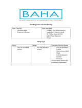
1. Insert crank handle in end of torsion rod. Then
secure with retaining pin. See (FIG. 12).
See subsection, "A. Required Kits" on
page 3 for torsion crank assembly.
2. IMPACT OR PINCH HAZARD.
Use extreme care when [winding / unwinding]
arm cap. If NOT controlled, rapid casting spin
off will occur. Spring tension will attempt to spin
the arm cap and/or fabric roller tube quickly and
unexpectedly. Failure to obey this warning could
result in death or serious injury.
Always have crank handle at 6 o’clock position
and turn toward the side of the RV.
Turn RH end cap counter-clockwise, and LH end
cap clockwise. See (FIG. 28) & (FIG. 29).
RH torsion MUST have awning safety lock
in roll down position.
The number of turns to achieve correct
torsion spring tension depends on awning
model and width. See the appropriate
torque specications table (below) for cor-
rect number of turns.
If awning is installed on RV and extended
2 revolutions (turns) from awning rail, ADD
2 turns to the number of turns in table.
FIG. 26
1
Table 1: Torsion Winding For (FIG. 26)
Awning Width
Number Of Turns
Rolled Up Extended
≤ 12' 5 11
12"-1" 14'
6 12
14"-1" 16'
7 13
16'-1" 18'
9 15
> 18' 10 16
Add 6 additional turns to torsion spring when awning is
fully extended.
WIND TORSION(S)
FIG. 27
1
Table 2: Torsion Winding For (FIG. 27)
Awning Width
Number Of Turns
Rolled Up Extended
≤ 12' 8 14
12'-1" 14'
9 15
14'-1" 16'
10 16
> 16' 12 18
Add 6 additional turns to torsion spring when awning is
fully extended.
FIG. 28
RH Torsion
Winding
Awning
Rail
RH End
Cap
FIG. 29
LH Torsion
Winding
Awning
Rail
LH End
Cap
3. Rotate FRTA (by hand) until hole (for nail) in left
end cap is located above arm cap. See (FIG. 8).
4. Insert a nail into hole in left end cap for positive
locking of FRTA. Place tape over nail to secure
in place. See (FIG. 8).
5. Repeat steps (1) through (4) for opposite side (if
applicable).

12
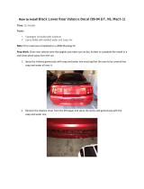
WIND TO
ADD TO RSIO N
L
E
F
T
R
I
G
H
T
ROLL
UP
ROLL
DN
FIG. 30
Right-Hand
End Cap "A"
Cut poly rope ush
with end of tube.
Valance
Open
Groove
Trim poly rope,
leaving sufcient
length to tuck in
place behind the
open groove.
Place open notch
in alignment with
open groove.
Fabric without
hemmed edge.
WIND TO
AD D T ORSIO N
L
E
F
T
R
I
G
H
T
ROLL
UP
ROLL
DN
FIG. 31
Right-Hand
End Cap "A"
Cut poly rope ush
with end of tube.
Valance
Open
Groove
Trim poly rope,
leaving sufcient
length to tuck in
place behind the
open groove.
Fabric edge folded
and hemmed.
Place open notch in
alignment with fabric groove.
WIND TO
AD D T ORSIO N
L
E
F
T
R
I
G
H
T
ROLL
UP
ROLL
DN
FIG. 32
Right-Hand
End Cap "B"
Cut poly rope ush
with end of tube.
Valance
Open
Groove
Trim poly rope,
leaving sufcient
length to tuck in
place behind the
open groove.
Fabric edge folded
and hemmed.
Place open notch in
alignment with fabric groove.
WIND TORSION(S)

13
WIND TO
AD D T ORSIO N
L
E
F
T
R
I
G
H
T
R OLL
UP
R OLL
DN
FIG. 33
Right-Hand
End Cap "B"
Cut poly rope ush
with end of tube.
Valance
Open
Groove
Trim poly rope,
leaving sufcient
length to tuck in
place behind the
open groove.
Place open notch
in alignment with
valance groove.
Fabric without
hemmed edge.
FIG. 34
Right-Hand
End Cap "C"
Cut poly rope ush
with end of tube.
Valance
Open
Groove
Trim poly rope,
leaving sufcient
length to tuck in
place behind the
open groove.
Fabric without
hemmed edge.
Place open notch in
alignment with fabric groove.
FIG. 35
Right-Hand
End Cap "C"
Cut poly rope ush
with end of tube.
Valance
Open
Groove
Trim poly rope,
leaving sufcient
length to tuck in
place behind the
open groove.
Fabric edge folded
and hemmed.
Place open notch in
alignment with open groove.
WIND TORSION(S)

14
REATTACH TORSION(S) TO AWNING HARDWARE
This section applies to awning fabric, fabric roller tube, and
torsion replacement.
If awning is installed on RV, the following procedures
MUST be performed:
● with FRTA extended 2 revolutions (turns) from
awning rail, and
● while on a stepladder.
A. Attach Torsion To Hardware
1. Insert arm cap into main arm. See (FIG. 37).
FIG. 37
FRTA
Hex Head Screw
Arm Cap
Torsion Rod
Lock
Nut
2. Assemble torsion rod of FRTA to main arm,
aligning hole through torsion rod with holes in
main arm and arm cap.
3. Reinstall hex head screw (with washer) through
main arm, arm cap, and torsion rod, securing
with lock nut. See (FIG. 37).
B. Remove Nails
IMPACT OR PINCH HAZARD. Do
NOT remove nail from torsion rod (at end cap) un-
til BOTH arm caps are secured to corresponding
front channels, and awning safety lock lever is in
roll down position. Otherwise, rapid casting spin off
will occur. Spring tension will attempt to spin the
hardware and/or fabric roller tube quickly and unex-
pectedly. Failure to obey this warning could result in
death or serious injury.
1. Remove nail from left end of torsion rod (LH end
cap), if applicable. See (FIG. 38).
FIG. 38
Nail
LH End Cap
Front Channel
2. With awning safety lock lever in roll down posi-
tion, remove nail from right end of torsion rod
(RH end cap), if applicable. See (FIG. 9).
If awning is NOT installed on RV, do NOT
remove nail at this time. Skip to section,
"Finish Installation" on page 15.
FIG. 36
Left-Hand End Cap
Fabric
Trim poly rope, leaving
sufcient length to tuck in
place behind the open groove.
Open Groove Valance
The Left-Hand end cap is
always placed with open notch
in alignment with open groove.
WIND TORSION(S)

15
FINISH INSTALLATION
This section applies to awning fabric and fabric roller tube
replacement, or if awning was removed from RV.
Some additional procedures may need to be per-
formed to complete the replacement. These pro-
cedures will vary in detail based on awning model.
See latest Installation Instructions for your specic
awning model.
Additional procedures may include:
● Secure awning fabric to awning rail.
● Secure hardware to RV.
● Remove RH nail AFTER awning is installed.
● Etc.
VERIFY INSTALLATION
A. Test Operation
Operate awning according to Operating Instruc-
tions (or User's Guide) to verify all parts are func-
tioning correctly.
B. Secure Awning For Travel
1. Fully close awning. See "Close Awning" in Oper-
ating Instructions (or User's Guide).
2. Verify awning is secure for travel. See "Close
Awning" in Operating Instructions (or User's
Guide).
C. Keep Literature
Keep these instructions with awning.
/