A&E Systems 5000 Replacement Instructions Manual

Type
Replacement Instructions Manual

A&E Systems 5000 awning provides an easy way to extend your living space outdoors. It features a sturdy aluminum frame and a durable fabric that is water-resistant and UV-protected, making it ideal for all-weather use. With its adjustable arms and multiple mounting options, you can customize the awning to fit your specific needs and preferences. Enjoy the outdoors in comfort and style with the A&E Systems 5000 awning.

A&E Systems 5000 awning provides an easy way to extend your living space outdoors. It features a sturdy aluminum frame and a durable fabric that is water-resistant and UV-protected, making it ideal for all-weather use. With its adjustable arms and multiple mounting options, you can customize the awning to fit your specific needs and preferences. Enjoy the outdoors in comfort and style with the A&E Systems 5000 awning.

1
Pop Rivet Tool
Adjustable Wrench
1/8" Drill Bit
Small File
Screwdriver
Electric Drill
Step Ladder
3/16" Pop Rivets
Vise Grips®
Socket Wrench Set
3/16" Drill Bit
1/8" Pop Rivets
Tools Required:Tools Required:
Tools Required:
TOP CASTING
AWNING
FABRIC
COTTER
PIN
MOVE LEVER POSITION TO
ROLL DOWN POSITION
RIGHT-HAND SIDE
(VIEWED FROM FRONT)
FIG. 2
Form No. 3103699.033 11/93
(Replaces 3103699.025 10/92)
© The Dometic Corp., LaGrange, IN 46761
FabricFabric
FabricFabric
Fabric
Roller Roller
Roller Roller
Roller
TT
TT
T
ubeube
ubeube
ube
For Models 5000, 7000, 7500, 8000, 8500, 9000, 9500For Models 5000, 7000, 7500, 8000, 8500, 9000, 9500
For Models 5000, 7000, 7500, 8000, 8500, 9000, 9500
& Grande Pavilion& Grande Pavilion
& Grande Pavilion
TT
TT
T
oror
oror
or
sion Assembsion Assemb
sion Assemb
ll
ll
l
yy
yy
y
REPLAREPLA
REPLAREPLA
REPLA
CEMENT INSTRCEMENT INSTR
CEMENT INSTR
UCTIONS FOR AUCTIONS FOR A
UCTIONS FOR A
WNINGWNING
WNINGWNING
WNING
A. GENERAL INSTRUCTIONSA. GENERAL INSTRUCTIONS
A. GENERAL INSTRUCTIONS
The Fabric Roller Tube Assembly (FRTA) consists of a
fabric, a roller tube and torsion assemblies.
For proper awning operation, the roller is under spring
tension from the torsion assemblies.
Improper release ofImproper release of
Improper release of
this spring tension can result in damage to the aw-this spring tension can result in damage to the aw-
this spring tension can result in damage to the aw-
ning, severe personal injury, or both.ning, severe personal injury, or both.
ning, severe personal injury, or both.
Service to the FRTA should be performed Service to the FRTA should be performed
Service to the FRTA should be performed
ONLY ONLY
ONLY ONLY
ONLY
by aby a
by aby a
by a
qualified service person.qualified service person.
qualified service person.
Read and understand the instructions before starting the
replacement of a fabric, a roller tube or a torsion assembly.
B.B.
B.B.
B.
REMO REMO
REMO REMO
REMO
VV
VV
V
AL OF AL OF
AL OF AL OF
AL OF
THE ATHE A
THE ATHE A
THE A
WNING FRWNING FR
WNING FRWNING FR
WNING FR
OM OM
OM OM
OM
THE COTHE CO
THE COTHE CO
THE CO
AA
AA
A
CHCH
CHCH
CH
NOTE:NOTE:
NOTE:NOTE:
NOTE: Awning removal from the coach is NOT neces-
sary when replacing a torsion assembly. Proceed to
Section C, Steps 1 & 2, Sections D, Steps 1-3, and
Section L, Steps 1-3.
4. Remove both of the patio feet from their mounting
brackets and extend the adjustable arms until each
patio foot rests on the ground and lock button locks in
hole.
5. Slide the awning fabric or roller cover out of the awning
rail.
a. To keep the 7500, 8000, 8500, 9000, 9500 and
Grande Pavilion Model Awnings from unwinding
during this step, be sure the cam lock lever is in the
roll down position. A 1/8" cotter pin can be inserted
in each torsion assembly for positive locking of the
roller tube. See FIG. 2.
1. In all instances of fabric or roller tube replacement, it
will be necessary to have a large work area to allow
complete unrolling of the awning. This work area must
be clean and smooth so the fabric will not be damaged.
2. Remove the TEK screws securing the awning fabric or
roller cover at each end of the awning rail. See FIG. 1.
3. Remove both top mounting brackets on the ends of the
awning rail. See FIG. 1
FIG. 1
1/2" TEK
SCREW
AWNING
RAIL
REMOVE FROM
BOTH SIDES
FABRIC
SECTION
TOP
BRACKET
2
NOTENOTE
NOTENOTE
NOTE: Some 5000 and 7000 Model Awning torsion
assemblies can not be pinned. If you have this type, the
torsion spring must be unwound before the awning can
be removed from the coach. Follow the instructions in
Section C, Steps 1 and 2.
b. To keep the 5000 or 7000 Model Awning from unwind-
ing, it must be pinned. See FIGS. 3 & 3A.
C.C.
C.C.
C.
UNWINDING A UNWINDING A
UNWINDING A
TT
TT
T
ORSION ASSEMBLORSION ASSEMBL
ORSION ASSEMBL
Y SPRINGY SPRING
Y SPRINGY SPRING
Y SPRING
NOTENOTE
NOTENOTE
NOTE: If the awning is installed on a coach, complete the
following steps on a step ladder, with the awning fabric
unrolled two feet from the awning rail.
1. Clamp a Vise Grip® tightly on the top casting. Remove
the 1/4-20 hex head machine screw from the top
casting. See FIG. 4.
WW
WW
W
ARNINGARNING
ARNINGARNING
ARNING
Severe injuries can result from the rapid spin-off ofSevere injuries can result from the rapid spin-off of
Severe injuries can result from the rapid spin-off of
the top casting. Use Vise Gripsthe top casting. Use Vise Grips
the top casting. Use Vise Grips®
- -
- -
-
NEVERNEVER
NEVERNEVER
NEVER
use bare use bare
use bare use bare
use bare
hands - to handle a top casting under springhands - to handle a top casting under spring
hands - to handle a top casting under spring
tension.tension.
tension.tension.
tension.
2. Take the top casting carefully out of the main support
arm (see NOTE below). Slowly let the torsion spring
unwind completely. Repeat Steps 1 & 2 for the opposite
end.
NOTENOTE
NOTENOTE
NOTE: If the awning's right-hand torsion assembly has
been pinned (5000 & 7000 Models), the cotter pin must be
removed from the torsion assembly before the spring can
be unwound. If the awning is an 8000, 8500, 9000, 9500 or
Grande Pavilion Model, the cam lock lever on the right-
hand torsion assembly must be turned clockwise to the roll
up position, before the spring can be unwound.
MAIN SUPPORT ARM
LOCKING
TAB
FIG. 3A
7000 MODEL AWNING7000 MODEL AWNING
7000 MODEL AWNINGFIG. 3
5000 MODEL AWNING5000 MODEL AWNING
5000 MODEL AWNING
COTTER PIN
MAIN SUPPORT ARM
LOCKING
TAB
COTTER PIN
LOCK
LEVER
TOP
CASTING
MAIN SUPPORT
ARM ASSEMBLY
VISE-
GRIPS®
1/4-20 X 1/2" HEX
HD. MACH. SET SCREW
FIG. 4
3
DD
DD
D
..
..
.
HO HO
HO HO
HO
W W
W W
W
TT
TT
T
O REMOO REMO
O REMOO REMO
O REMO
VE A VE A
VE A VE A
VE A
TT
TT
T
ORSION ASSEMBLORSION ASSEMBL
ORSION ASSEMBL
YY
YY
Y
1. Make sure the torsion spring has been relieved of its
tension (see Section C.)
2. Mark or make note of the location of the fabric and the
end cap on the roller tube. This is necessary to
reposition the new torsion, fabric or roller tube exactly
the same when the new part is installed.
3. Remove the two screws holding the torsion assembly
to the roller tube. If secured by pop rivets, drill out the
two rivets using a 3/16" drill bit. Remove assembly from
roller tube. See FIG. 5.
E.E.
E.E.
E.
HO HO
HO HO
HO
W W
W W
W
TT
TT
T
O REMOO REMO
O REMOO REMO
O REMO
VE FVE F
VE FVE F
VE F
ABRIC FRABRIC FR
ABRIC FRABRIC FR
ABRIC FR
OM ROM R
OM ROM R
OM R
OLLER OLLER
OLLER OLLER
OLLER
TUBETUBE
TUBETUBE
TUBE
1. Remove both torsions. See Section D, Steps 1-3 for
torsion removal.
2. Roll the awning completely out on a clean smooth
surface.
3. With the awning laying flat, slide the roller tube out from
fabric.
NOTE: When removing the fabric from the 9000 and 9500
Model awning, it is necessary to remove the 1/8" pop rivets
from both ends of the roller cover. Once the rivets are
removed, you can slide the fabric out of the cover. See FIG.
6 & 7.
FF
FF
F
..
..
.
INST INST
INST INST
INST
ALLING FALLING F
ALLING FALLING F
ALLING F
ABRIC ON RABRIC ON R
ABRIC ON R
OLLER OLLER
OLLER OLLER
OLLER
TUBETUBE
TUBETUBE
TUBE
1. Unfold the new fabric and lay it on top of the existing
fabric in the
exact same positionexact same position
exact same position. Be sure the new
fabric is the correct size and color. If roller tube is being
replaced, make sure it is the correct length and position
it the same as the original.
2. Guide the roller tube over the poly-rope(s) of the fabric.
Be careful not to damage the roller tube or the fabric.
NOTENOTE
NOTENOTE
NOTE: When changing the fabric, it is vital that the same
groove(s) be used. This eliminates the need to redrill any
holes (i.e. center support).
3. Center the fabric on the roller tube and hand-roll the
entire assembly in the same direction as the original
fabric.
G.G.
G.G.
G.
F F
F F
F
ABRIC REPLAABRIC REPLA
ABRIC REPLA
CEMENT ON 9000 CEMENT ON 9000
CEMENT ON 9000
WITH 7 SLAWITH 7 SLA
WITH 7 SLA
T RT R
T RT R
T R
OLLER COOLLER CO
OLLER COOLLER CO
OLLER CO
VERVER
VERVER
VER
RIVETS DRILLED OUT
ROLLER TUBE
FABRIC UNROLLED
SLIDE OUT TORSION ASSEMBLY
FIG. 5
Installing a new replacement fabric on a Model 9000Installing a new replacement fabric on a Model 9000
Installing a new replacement fabric on a Model 9000
roller cover with 7 slats and a vinyl strip. See FIG. 6:roller cover with 7 slats and a vinyl strip. See FIG. 6:
roller cover with 7 slats and a vinyl strip. See FIG. 6:
1. Remove vinyl strip
AA
AA
A (FIG. 11) and hinge slat
BB
BB
B (FIG.
10) from top slat
CC
CC
C (FIG. 8). Discard both vinyl strip
AA
AA
A
and hinge slat
BB
BB
B.
2. Remove top slat
CC
CC
C (FIG. 8) from roller cover assembly
and keep to be installed later.
3. The new replacement fabric will be installed as shown
in FIG.
77
77
7.
4. Use a small file to round the ends of the groove in the
5/16" channel of the main slat
DD
DD
D (FIG. 9).
5. Slide the 5/16" channel of the main slat
DD
DD
D onto the poly-
rope located approximately 12" from the top edge of the
fabric.
6. Install two pop rivets in the main slat
DD
DD
D on both ends to
prevent the fabric from shifting in roller cover. If a new
roller cover assembly is being installed, a 1/8" hole will
need to be drilled 1-1/2" to 2" from end of the main slat
for the pop rivets. To prevent damage, be sure to
remove any burrs left by the drill.
7. Use a small file to round the ends of the 5/16" grooves
on the top slat
CC
CC
C (FIG. 8) to prevent tearing of the fabric.
Slide the top slat
CC
CC
C onto both the 1/4" channel of the fifth
main slat
DD
DD
D and the polly-rope 1-1/2" from the edge of
the fabric.
8. Install the screws into the edge of the roller cover
assembly. See FIG. 7.
4
1/4" CHANNEL
TOP SLAT "C"
VIEW RH END
MAIN SLAT "D"
VIEW RH END
HINGE SLAT "B"
INSTALL A 1/8"
POP RIVET
EACH END
D
D
D
D
D
C
INSTALL A 1/8"
POP RIVET
EACH END
D
D
D
D
D
C
VINYL STRIP "A"
E
HINGE SLAT "B"
FIG. 6FIG. 6
FIG. 6FIG. 6
FIG. 6
FIG. 7FIG. 7
FIG. 7FIG. 7
FIG. 7
E
5/16" CHANNEL
INSTALL TOWARD
CANOPY
FIG. 10FIG. 10
FIG. 10FIG. 10
FIG. 10
FIG. 9FIG. 9
FIG. 9FIG. 9
FIG. 9
FIG. 8FIG. 8
FIG. 8FIG. 8
FIG. 8
FIG. 11FIG. 11
FIG. 11FIG. 11
FIG. 11
VINYL STRIP "A"
FOR FIGS. 6—11FOR FIGS. 6—11
FOR FIGS. 6—11
A - VINYL STRIPA - VINYL STRIP
A - VINYL STRIP
B - HINGE SLAB - HINGE SLA
B - HINGE SLA
TT
TT
T
C - C -
C - C -
C -
TT
TT
T
OP SLAOP SLA
OP SLAOP SLA
OP SLA
TT
TT
T
D - MAIN SLAD - MAIN SLA
D - MAIN SLA
TT
TT
T
E - AE - A
E - AE - A
E - A
WNING RAILWNING RAIL
WNING RAIL
FIGURES 6 FIGURES 6
FIGURES 6 FIGURES 6
FIGURES 6
THRTHR
THRTHR
THR
OUGH 11OUGH 11
OUGH 11OUGH 11
OUGH 11
5/16" CHANNEL
BOTH ENDS
1/4" CHANNEL
INSTALL TOWARD
AWNING RAIL
5/16" ROD IN
AWNING RAIL
3/8" CHANNEL
FOR VINYL
STRIP "A"
5
H.H.
H.H.
H.
F F
F F
F
ABRIC REPLAABRIC REPLA
ABRIC REPLA
CEMENT ON 9000/9500 CEMENT ON 9000/9500
CEMENT ON 9000/9500
WITH 6 SLAWITH 6 SLA
WITH 6 SLA
T RT R
T RT R
T R
OLLER COOLLER CO
OLLER COOLLER CO
OLLER CO
VERVER
VERVER
VER
I.I.
I.I.
I.
INST INST
INST INST
INST
ALLING NEW RALLING NEW R
ALLING NEW R
OLLER COOLLER CO
OLLER COOLLER CO
OLLER CO
VER VER
VER VER
VER
WITH 7 SLAWITH 7 SLA
WITH 7 SLA
TS & TS &
TS & TS &
TS &
VINYL STRIPVINYL STRIP
VINYL STRIP
Installing new roller cover on 9000 model with 7 slatsInstalling new roller cover on 9000 model with 7 slats
Installing new roller cover on 9000 model with 7 slats
and a vinyl strip. See FIG. 6.and a vinyl strip. See FIG. 6.
and a vinyl strip. See FIG. 6.
1. Use a file to round the ends of the groove in the 5/16"
channel of the main slat
DD
DD
D (FIG. 9).
K.K.
K.K.
K.
REPLA REPLA
REPLA REPLA
REPLA
CING CING
CING CING
CING
TT
TT
T
ORSION ASSEMBIESORSION ASSEMBIES
ORSION ASSEMBIES
1. Fold the poly-rope ends into the roller tube. This
prevents the fabric from shifting. Make sure the ends of
the poly-rope do not interfere with the cam lock.
2. Reinstall the torsion assembly in the roller tube. Align
the screw/rivet slots on the end cap with the holes in the
roller tube - in the exact same position as in Section D,
Step 2.
NOTENOTE
NOTENOTE
NOTE: If the roller tube is new, the rivet holes are not drilled.
The torsion assemblies must be positioned as follows:
All Models (except the 5000)All Models (except the 5000)
All Models (except the 5000): The left-hand torsion
assembly position
has the slotted groove in the end
cap aligned with the empty groove of the roller tube.
All Models (except the 5000, 9500 & Grande Pavil-All Models (except the 5000, 9500 & Grande Pavil-
All Models (except the 5000, 9500 & Grande Pavil-
ion)ion)
ion)ion)
ion): The right-hand torsion assembly position has the
slotted groove in the end cap aligned with the empty
groove in the roller tube.
2. Slide the 5/16" channel of the main slat
DD
DD
D onto the poly-
rope.
3. Drill a 1/8" hole 1-1/2" to 2" from end of the main slat.
Install a 1/8" pop rivet. Do both ends to secure the
fabric.
JJ
JJ
J
..
..
.
INST INST
INST INST
INST
ALLING NEW RALLING NEW R
ALLING NEW R
OLLER COOLLER CO
OLLER COOLLER CO
OLLER CO
VER VER
VER VER
VER
WITH 6 SLAWITH 6 SLA
WITH 6 SLA
TSTS
TSTS
TS
Installing new roller cover on model 9000 and 9500Installing new roller cover on model 9000 and 9500
Installing new roller cover on model 9000 and 9500
with 6 slats. See FIG. 7.with 6 slats. See FIG. 7.
with 6 slats. See FIG. 7.
1. Follow steps 1-8 in Section G.
Installing a new replacement fabric on 9000 and 9500Installing a new replacement fabric on 9000 and 9500
Installing a new replacement fabric on 9000 and 9500
model awning roller cover with 6 slats. See FIG. 7.model awning roller cover with 6 slats. See FIG. 7.
model awning roller cover with 6 slats. See FIG. 7.
1. Follow steps 2-8 in Section G.
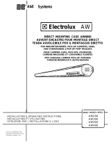
EMPTY ROLLER
TUBE GROOVE
POLY
TUBING
SECTION
FABRIC
VEHICLE SIDE VEHICLE SIDE
VIEW
FROM
REAR
VIEW
FROM
FRONT
END
CAP
LUG
FIG. 12
END
CAP
LUG
On the right-hand torsion assembly for the 9500 &On the right-hand torsion assembly for the 9500 &
On the right-hand torsion assembly for the 9500 &
Grande PavilionGrande Pavilion
Grande Pavilion: Align the slot in the end cap with the
next slot counterclockwise (as viewed from the right
end) from the empty slot.
On the 5000 AwningOn the 5000 Awning
On the 5000 Awning: The lug on the left-hand torsion
assembly should be positioned at "11:00" and the right-
hand at "1:00" in relationship to the empty groove. See
FIG. 12.
NOTENOTE
NOTENOTE
NOTE: Placing the end caps as suggested usually
positions the lock lever or lugs in the proper position
when awning is closed. The awning should be opened
and closed several times, and checked. The models
with the cam lock lever should be at "11:00" and the
lugs of the 5000 and 7000 models should be at the
"12:00" position . The end cap may have to be removed
and repositioned if it is not in the proper location. See
FIG. 13.
Models 8500 and 9000 22' - 25' have been manufac-
tured with both standard and heavy duty torsion springs.
Before reinstalling the torsion, properly identify (Stan-
dard or Heavy Duty) the springs. This is necessary for
proper winding of the torsion. See Spring Identification
Chart on page 6.
Secure torsion assemblies to roller using 3/16" dia. x 3/8"
long stainless steel pop rivets.
NOTENOTE
NOTENOTE
NOTE: DO NOT reuse self-
tapping screws.
3/8" MIN.
EXTENSION
RAFTER
ARM
TOP CASTING
MAIN
SUPP'T.
ARM
TOP MTG.
BRACKET
FIG. 13
!CAUTION
6
L.L.
L.L.
L.
REWINDING REWINDING
REWINDING REWINDING
REWINDING
TT
TT
T
ORSION ASSEMBLORSION ASSEMBL
ORSION ASSEMBL
Y SPRINGY SPRING
Y SPRINGY SPRING
Y SPRING
2. Rewind the torsion assembly to the number of turns
indicated by the torsion assembly Torque Chart and in
the direction shown in FIGS. 14 &15.
NOTENOTE
NOTENOTE
NOTE: If the awning is installed on a coach, complete the
following steps on a step ladder with the awning fabric
unrolled two feet from the awning rail.
1. Clamp a Vise Grip® tightly on the thickest side of the
top casting. See FIG. 4.
WW
WW
W
ARNINGARNING
ARNINGARNING
ARNING
Severe injury can result from the rapid spin-off of theSevere injury can result from the rapid spin-off of the
Severe injury can result from the rapid spin-off of the
top casting. Use Vise Gripstop casting. Use Vise Grips
top casting. Use Vise Grips®
- NEVER use bare hands - NEVER use bare hands
- NEVER use bare hands
- to handle a top casting under spring tension.- to handle a top casting under spring tension.
- to handle a top casting under spring tension.
3. Place a 1/8" cotter pin through the hole in the end cap
and torsion rod. This will prevent the rapid spin-off of
the top casting during installation of the awning. See
FIGS. 2, 3 & 3A.
NOTENOTE
NOTENOTE
NOTE: If awning is installed on the coach, place the top
casting in the support arm and secure with the 1/4-20 hex
head bolt.
AWNING RAIL AWNING RAIL
WIND TOP
CASTING
WIND TOP
CASTING
FIG. 14
FIG. 15
RIGHT-HAND SIDE
(VIEW FROM FRONT)
LEFT-HAND SIDE
(VIEW FROM REAR)
Number of Turns
MODEL NUMBER
5000 7000 7500 9500
Awning Length (Ft.) 8000 Grande Pavillion
8500
9000
86-8-
96-8-
10 6 8 8 -
10' 8" 6 8 8 -
11 6 8 8 -
12 6 8 8 -
13 7 9 9 -
14 7 9 9 -
15 8 10 10 -
16 8 10 10 6
16'6" - - 12 -
17 10 12 12 6
18 10 12 12 7
19 11 13 13 7
19'6" - - 13 -
20 11 13 13 -
21 11 13 13 8
22 12 - 14 8
23 12 - 14 8
24 12 - 14 9
25 12 - 14 9
TORSION ASSEMBLY TORQUE SPECIFICATIONS
Painted red cap
end and no paint
on stabilzier end.
Painted red cap
end and white on
stabilzier end.
No paint on either
end.
Painted white on
cap end and no
paint on stabilizer
end.
Length
22' 14 8
23' 14 8
24' 14 8
25' 14 8
Wire Dia.Wire Dia.
Wire Dia.Wire Dia.
Wire Dia. .120 .140
RHRH
RHRH
RH
LHLH
LHLH
LH
StandardStandard
StandardStandard
Standard
Heavy DutyHeavy Duty
Heavy Duty
SPRING IDENTIFICATION CHART
TURNS OF TENSIONTURNS OF TENSION
TURNS OF TENSION
See Spring Indentification Chart for No. of Turns
M.M.
M.M.
M.
INST INST
INST INST
INST
ALLING AALLING A
ALLING AALLING A
ALLING A
WNING ON COWNING ON CO
WNING ON CO
AA
AA
A
CHCH
CHCH
CH
1. Follow installation instructions for the awning when replacing on coach.
  • Page 1 1
  • Page 2 2
  • Page 3 3
  • Page 4 4
  • Page 5 5
  • Page 6 6

A&E Systems 5000 Replacement Instructions Manual

Type
Replacement Instructions Manual

A&E Systems 5000 awning provides an easy way to extend your living space outdoors. It features a sturdy aluminum frame and a durable fabric that is water-resistant and UV-protected, making it ideal for all-weather use. With its adjustable arms and multiple mounting options, you can customize the awning to fit your specific needs and preferences. Enjoy the outdoors in comfort and style with the A&E Systems 5000 awning.

Ask a question and I''ll find the answer in the document

Finding information in a document is now easier with AI