Page is loading ...

The Cable Connection
52 Heppner Drive
Carson City, NV 89706
800.851.2961
775.885.1443
Fax 775.885.2734
e-mail: info@ultra-tec.com
www.ultra-tec.com
March 1, 2020
INSTALLATION GUIDE

800.851.2961 • 775.885.1443
Ultra-tec
®
, Invisiware
®
, Adjust-A-Body
®
, Adjust-A-Jaw
®
, Push-Lock
®,
and Pull-Lock
®
are registered trademarks of
The Cable Connection, Carson City, NV 89706.
© 2020 The Cable Connection, Carson City, NV 89706. All rights reserved.
TABLE OF CONTENTS
Page
Before You Get Started
Rail Finish ...............................................................................................................................1
Materials Required ................................................................................................................1
Tools Required .................................................................................................................. 1–2
Installing Grommets ...................................................................................................................... 2
Measuring and Installing Cable—Horizontal Railings
Measuring Cable Lengths .................................................................................................... 3
Installing Cable ................................................................................................................. 4-9
Tensioning Cables ................................................................................................................. 9
Wood Railings—Mounting Alternatives/Hole Drilling ................................................. 10-12
Measuring and Installing Cable—Vertical Railings ............................................................ 1 3-14
Swaging Instructions ...............................................................................................................15-16
Ultra-tec
®
“Clip-On” Fixed Jaw Installation Instructions .......................................................17
Using Invisiware
®
Receivers on Stairways ......................................................................... 18-19
Push-Lock
®
Fittings Installation Instructions .................................................................. 20-22
Pull-Lock
®
Stop-End Fittings Installation Instructions .................................................. 23-24
Receiver with Push-Lock
®
Stud Installation Instructions .............................................. 25-28
Swageless Tensioner Installation Instructions .................................................................. 29-31
Push-Lock
®
Turnbuckle Installation Instructions ............................................................ 32-33
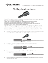
PL-Key Instructions ...................................................................................................................... 34

1
WWW.ULTRA-TEC.COM
Before You Get Started
Model 650 Swager
for 1/8" through
3/8" cable.
Electric Hydraulic
120V Pump
Model 610 Swager
kit for 1/8" and
3/16" cable.
<
<
Rail Finish
If your rail is to be painted, powder coated
or otherwise finished in any way, we strongly
recommend that you apply the finish after all holes
are drilled and prior to stringing the cable.
Materials Required
Some parts require screws to mount them to your
railing. If they were not ordered from the factory, then
you will need to obtain mounting screws for the parts
shown in the chart below.
Tools Required
The tools listed here assume you will be swaging at
least one end of the cable in the field using an
Invisiware field swager. If no field swaging is
required, only those tools indicated with * may
be required.
*Cable Cutters.
C9 for cables up to 3/16"; C12 for cables larger
than 3/16".
Air Compressor.
Minimum 5.8 c.f.m. at 90 p.s.i. and a minimum
20-gallon tank. Air pressure should be regulated to a
minimum of 120 p.s.i., not to exceed 140 p.s.i.
In areas prone to tampering, a permanent setting
thread sealant is recommended for use with screws.
SCREW
REQUIRED
1/4-28 x 1/2"
3/8-24 x 3/4"
FOR CABLE
DIAMETER
1/8" or 3/16"
1/4", 5/16", 3/8"
FACTORY
PART NO.*
SC-6
SC-8
PART
NUMBERS
Adjust-A-Jaw
®
Tensioners
A-J62
A-J82
A-J122
Adjust-A-Body
®
with Threaded
Eye Tensioners
A-JTE6
A-JTE8
Push-Lock
™
with Threaded
Eye Fittings
PL-TE4
PL-TE6
1/4-28 x 1/2"
3/8-24 x 3/4"
1/8" or 3/16"
1/4"
1/8"
3/16"
1/4-28 x 1/2"
SC-6
SC-8
SC-6
*Factory supplied screws are stainless steel button-head screws.
Ultra-tec Portable Pneumatic/Hydraulic Swager.
(If you are renting one from the factory or a stocking
distributor, be sure to specify the uncoated
diameter of the cable you are swaging, so the
correct swager will be supplied. Rented swagers
generally come with most other special tools
required to field swage and install cable, including
hose fittings, cable grip locking pliers, cable cutter,
and GO gauge for measuring the swaged diameter
of Invisiware Radius Ferrules. A pre-tensioner can
also be furnished upon request.)
<

2
800.851.2961 • 775.885.1443
Installing Grommets
IMPORTANT NOTE: If grommets are being used on
intermediate posts, cable braces, or in the cable
exit hole of end posts, then grommets should be
installed before cable is run.
To install grommets, see Fig. K below. Place the
larger diameter of the grommet onto the grommet
installation tool and the smaller diameter at the hole
in the post. Tap the tool lightly with a hammer.
Tools Required (continued)
*Ultra-tec Pre-tensioning Tool (optional).
Since some Invisiware hardware has a minimum of
take-up on longer runs (over 30 feet) you may want
to use a pre-tensioning tool. In ordering, be sure to
specify the cable diameter you will be using it with.
*Cable Grip Locking Pliers. To grip the cable while
tensioning the end fittings without damaging the
cable. (Available from the factory).
*Wrenches. If installing Invisiware Receivers
(including when they are used with Push-Lock studs),
an Allen wrench to tension the cable.
See chart below.
If installing Adjust-A-Jaw, Adjust-A-Body, or
Push-Lock stud tensioners, an open-end wrench to
tension the cables. See chart below.
3/16"
7/32"
5/16"
1/8" or 3/16"
1/4"
5/16" or 3/8"
R-6-12 thru R-6-82
R-8-22 thru R-8-52
R-12-32 thru R-12-52
PART
NUMBERS
FOR CABLE
DIAMETER
HEX
HOLE SIZE
Calipers, if you are swaging and installing
Invisiware Radius Ferrules, you will need a means to
measure the diameter of the swaged fitting.
(“GO” gauges for this purpose are normally included
with Ultra-tec Portable Swagers when rented from
the factory).
Grommet Installation Tool (available from the
factory), and hammer if you will be installing
grommets.
*Drills and Drill Bits as required, if installing in a
wood railing—see Wood Railings under “Measuring
and Installing Cable—Horizontal Railings".
*Cut-off Kit, if using Pull-Lock fittings.
OPEN-END
WRENCH SIZE
7/16"
9/16"
11/16"
FOR CABLE
DIAMETER
1/8" or 3/16"
1/4"
5/16" or 3/8"
TENSIONER
PART NUMBERS
Adjust-A-Jaw
A-J62
A-J82
A-J122
Adjust-A-Body
ANY
ANY
Receiver with
Push-Lock
Stud
PLST-4, PLST-6
Push-Lock
Tensioner
ANY
Push-Lock
Turnbuckle
ANY
7/16"
9/16"
1/8" or 3/16"
1/4"
1/8" or 3/16"
1/8" or 3/16"
1/8" or 3/16"
3/8"
3/8" and
two 7/16"
wrenches
3/8" (need two)

3
WWW.ULTRA-TEC.COM
Measuring and Installing Cable
Horizontal Railings
Measuring Cable Lengths
This section applies only if you will be cutting and swaging the cables. If you have ordered your cables cut to
length with fittings already swaged on, or you are using swageless fittings (Pull-Lock, Push-Lock, Receiver with
Push-Lock stud, Swageless Tensioners, Push-Lock Turnbuckle), you can skip this section on “Measuring Cable
Lengths.”
1. Measure the length of the run from the outside of one terminating end post to the other terminating end post. Over
estimate when corners are involved. See Figures A and B below.
2. Measure out cable on a relatively clean
surface (see Figure B below). A lawn or
swept concrete surface would be fine.
Cut cable to length using Cable Cutter.
Note: Make sure that the zero end
is held firmly, so that it cannot move.
Cutting the cables takes very little time.
It is best to have one person hold the
cable at the zero end while another
operates the cable cutter at the
cut mark.
Intermediate posts should be no more than 48" apart.
If you are using Push-Lock or Pull-Lock fittings, Receivers with Push-Lock Studs,
Swageless Tensioners, or Push-Lock Turnbuckles, see separate instructions on pages 20-33.

4
800.851.2961 • 775.885.1443
Where Invisiware Receivers are being used:
Swage the stud onto the end of the cable to be attached to
Post A (see “Swaging Instructions,” pages 15-16).
Where Adjust-A-Jaw or Adjust-A-Body Tensioners are being used:
Slide the Body onto the cable and swage the Ferrule onto the end
of the cable to be attached to Post A (see “Swaging Instructions,”
pages 15-16).
Where Ultra-tec Fixed Jaws are being used:
Slide the Fixed Jaw onto the cable and swage the Ferrule onto the
end of the cable to be attached to Post A (see “Swaging Instructions,”
pages 15-16).
B. FEED CABLE THROUGH INTERMEDIATE POSTS
Feed the bare end of the cable through all your intermediate posts and braces to Post B.
END
POST
B
END
POST
A
With one fitting
already swaged
onto cable,
feed bare end of cable
through this end post first.
Cut bare end
INTERMEDIATE POST OR CABLE BRACE
NOTE: Intermediate posts should be no more than 48" apart.
A. SWAGE CABLES
Unless already swaged (attached to the cables), swage the fittings to be used onto one end of the cut cables
(see “Swaging Instructions,” pages 15-16).
Where Invisiware Radius Ferrules will be used:
1) Slide the washer onto the cable.
2) Swage the Radius Ferrule onto the end of the cable
(see “Swaging Instructions,” pages 15-16) .
3) Slide the washer over the body of the Radius Ferrule.
4) Feed the bare end of the cable through the hole in
Post A from the back side, until the fitting’s head with
washer rests against the back side of the post
(or in the counterbore if applicable).
Installing Cable (continued)

5
WWW.ULTRA-TEC.COM
Installing Cable (continued)
C. ATTACH FITTINGS TO END POST A.
If using Ultra-tec Fixed Jaw:
Bolt the fitting to the tab, through the hole in the
structural tee, or the lag eye (in wood post) on
the end post, using the screws specified under
“Materials Required.”
Screw the lock nut onto the threads of the clevis or
eye, then hold the cable closely behind the body and
turn the body by hand at least 6 full turns onto the
threaded end of the clevis. (See note at right)*
If using Adjust-A-Jaw or
Adjust-A-Body with Threaded Eye tensioners:
If you are installing the tensioner using tabs,
holes in a structural tee, or lag eyes (in wood),
attach the clevis portion of the fitting to the tab, lag
eye, or through the hole of the structural tee on
the end post, use the screws specified under
“Materials Required.”
If you are installing into wood with a hanger bolt, screw
the hanger bolt into a pre-drilled pilot hole in the post.
Screw the lock nut onto the threads of the bolt, then
hold the cable closely behind the body and turn the
body by hand at least 6 full turns onto the threaded
end of the bolt. (See note below)*
If you are installing into a threaded hole in a metal post,
screw the bolt into the threaded hole in the post.
Screw the lock nut onto the threads of the bolt, then
hold the cable closely behind the body and turn the
body by hand at least 6 full turns onto the threaded
end of the bolt. (See note below)*
*NOTE: This will allow for maximum take-up. The fewer
turns you make at this step, the more thread that will
be exposed when the installation is complete. Each job
is different, so we suggest that you string and lightly
tension one cable between end posts, to determine
how many turns you will make in turning the body onto
the male threaded end in order to minimize the amount
of exposed thread at both ends.
If you are installing an Adjust-A-Body concrete anchor bolt
end into a concrete anchor bolt, screw the bolt into the
threaded hole in the anchor bolt. Screw the lock nut
onto the threads of the bolt, then hold the cable closely
behind the body and turn the body by hand onto the
threaded end of the bolt at least 6 full turns.
(See note below)*

6
800.851.2961 • 775.885.1443
Installing Cable (continued)
DOUBLE END POST CONSTRUCTION
E. ATTACH FITTINGS AT END POST B
If installing Invisiware Receiver at Post B:
NOTE: If installing Invisiware Receiver on a stairway, see “Using
Invisiware Receivers on Stairways” before proceeding.
1. Cut cable at Post B end. (Assumes cable is already
attached to Post A.)Mark and cut the cable at the
location shown in relation to end Post B (see Figure R
below for steel posts, Figure RW below for wood posts).
NOTE: this cut mark will allow for maximum take-
up. However, it may leave more thread exposed than
necessary after tensioning. This length can be altered
to achieve the most favorable results.
1.00˝
1.25˝
For wood posts, follow the same instructions, except
you will have to feed the cable (with the stud swaged
on the end) through the post from the inside to meet
the Receiver inside the post, where you will turn the
Receiver onto the stud using an Allen wrench.
D. PULL CABLE TOWARD END POST B.
Use Ultra-tec Pre-tensioning Tool, if required (see below).
If you are using Invisiware Radius Ferrule:
Make sure the fitting is through the hole in the back
of the post with the head with washer resting against
the back side of the post (or in the counterbore if
applicable) as you proceed to the next step.
If using Invisiware Receiver:
Slide the washer over the body of the Receiver, then
feed the Receiver through the hole in back of the post
and into the hole on inside wall of the post (metal).
If you have a metal double post end post construction,
be sure to place spacers between the double posts, as
you feed the fitting through.
By hand, screw the Receiver onto the threaded stud at
least 6 full turns.

7
WWW.ULTRA-TEC.COM
2. Swage stud onto cable (see “Swaging Instructions,”
pages 15-16).
3. Slide the washer over the body of the Receiver, then
feed the Receiver through the hole in the back of the
post. If you have a double post end post construction,
be sure to place spacers between the double posts,
as you feed the fitting through. By hand, screw the
Receiver onto the swaged stud at least 6 full turns.
Do not tension cables until all cables have been
installed between end posts A and B.
For wood posts, follow the same instructions, except
you will have to feed the cable (with the stud swaged
on the end) through the post from the inside to meet
the Receiver inside the post, where you will turn the
Receiver onto the stud using an Allen wrench.
4. Repeat above steps for each cable to be installed
between end posts A and B.
DOUBLE END POST CONSTRUCTION
Installing Cable (continued)
5. After all the cables have been installed, tension the
cable to a minimum of 225 lbs. by holding the cable
(using cable grip locking pliers) closely behind the
stud. Turn the Receiver clockwise with an Allen wrench
(see Figure U). See “Tensioning Cables“
(page 9) for sequence to use in tensioning cables.
If installing Adjust-A-Jaw or Adjust-A-Body
tensioner at Post B:
1. Cut cable at Post B end. (Assumes cable is already
attached to Post A).
If you are attaching the tensioner to a tab, lag eye
or hole in a structural tee, mark and cut the cable
at the location shown in relation to the center of the
mounting hole at Post B (see Figure T below).
NOTE: this cut mark will allow for maximum take-up.
However, it may leave more thread exposed than
necessary after tensioning. This length can be altered
to achieve the most favorable results.

8
800.851.2961 • 775.885.1443
If the tensioner is mounted with the bolt screwed into a
wood post, a threaded hole in a metal railing, or a
concrete anchor, mark and cut the cable at the location
shown in relation to end Post B (see figures below).
NOTE: this cut mark will allow for maximum take-
up. However, it may leave more thread exposed than
necessary after tensioning. This length can be altered
to achieve the most favorable results.
3. Attach Tensioner to post.
If you are installing the tensioner using tabs, holes in a
structural tee, or lag eyes (in wood) attach the clevis or
eye portion of the fitting to the tab, lag eye, or through
the hole in structural tee on the end post, using the
screws specified under “Materials Required.”
Screw the lock nut onto the threads of the clevis or eye,
then hold the cable closely behind the body and turn
the body by hand onto the threaded end of the clevis at
least 6 full turns.
If you are installing into wood with a hanger bolt, screw
the hanger bolt into a pre-drilled pilot hole in the post.
Screw the lock nut onto the threads of the bolt, then
hold the cable closely behind the body and turn the
body by hand onto the threaded end of the bolt at least
6 full turns.
If you are installing into a threaded hole in a metal post,
screw the bolt into the threaded hole in the post.
Screw the lock nut onto the threads of the bolt, then
hold the cable closely behind the body and turn the
body by hand onto the threaded end of the bolt at
least 6 full turns.
Installing Cable (continued)
2. Slide the Body onto the cable and swage the Ferrule
onto the end of the cable (see “Swaging Instructions,”
pages 15-16).

9
WWW.ULTRA-TEC.COM
Installing Cable (continued)
If you are installing an Adjust-A-Body concrete anchor bolt
end into a concrete anchor bolt, screw the bolt into the
threaded hole in the anchor bolt. Screw the lock nut
onto the threads of the bolt, then hold the cable closely
behind the body and turn the body by hand onto the
threaded end of the bolt at least 6 full turns.
4. Repeat the above steps for each cable to be installed.
Do not tension the cables, until all cables have been
installed between end posts A and B.
5. After all the cables have been installed, tension the
cable to a minimum of 225 lbs. with an open end
wrench, holding the cable with cable grip locking pliers
to prevent it from rotating (see illustration below).
See “Tensioning Cables” (at right) for sequence to use
in tensioning cables.
6. If tensioners are mounted to tabs, structural tees or lag
eyes, tighten the mounting screws.
7. On all installations, tighten the lock nut against
the body of the fitting with an open-end wrench.
NOTE: In areas prone to tampering, the use of permanent
setting thread sealant is recommended for
mounting screws and lock nuts.
F. TENSIONING CABLES
Tension all cables in sequence, beginning with the center
cables, moving up and down toward the top and
bottom (see Figure V below).

10
800.851.2961 • 775.885.1443
S/S WASHER
PUSH-LOCK
®
OR
PULL-LOCK
®
FITTING
PUSH-LOCK
®
WITH
THREADED EYE
RECEIVER WITH PUSH-LOCK
®
STUD TENSIONER WITH S/S
WASHER
RECEIVER WITH PUSH-LOCK
®
STUD TENSIONER
WITH S/S WASHER
PUSH-LOCK
®
LAG
Wood Railings—Mounting Alternatives
The following illustrations demonstrate how the hardware can be used on a single corner post. Not all possible
hardware combinations are shown. If the hardware and cable run all the way through the post in one direction, you
will need to use a hanger bolt end or hardware that is mounted to a lag for the perpendicular direction.

11
WWW.ULTRA-TEC.COM
1/8", 3/16"
1/8", 3/16"
1/4",
5/16", 3/8"
LE-6
LE-6L
LE-8
7/32"
7/32"
3/8"
A-JB6
A-JB6-L
PL-L4/6
PL-TB-HB-4/6
PL-TB-HBL-4/6
3/8"
USING PART NO.
USE
DRILL SIZE
CABLE
SIZE
7/32"
1/8"
3/16"
PL-LAG-4/6
PL-SFC-WS-4
PL-SFC-WP-4-1
PL-LAG-CL-TE4-1
1/4" A-JB8
Hole Diameter
Using
Push-Lock® or
Pull-Lock® Fittings
Cable
Size
Using
Threaded Studs
Hole Diameter Where Cables Supplied by Factory
with Fittings Swaged on Both Ends of Cable
Using Ferrules for
Clip-on Fixed Jaws
Hole Diameter Where
Studs/Ferrules are
Swaged in the Field
or Swageless Fittings are
Put on the Cables
Drilling Holes in Intermediate Posts and Cable Braces
Wood Railings—Mounting Alternatives (continued)
Drilling Holes in End Posts for Cable Mounting Hardware
Where hardware that requires mounting with lag fittings is being used, drill holes in the end posts using the drill size shown
on the following chart and screw lags into the holes. The Fixed Jaws, Adjust-A-Jaw and Adjust-A-Body with Threaded Eye
tensioners, or Push-Lock Lags and Push-Lock with Threaded Eyes will be mounted to the lags.
Where tensioners with Hanger Bolts are being used, drill holes in the end posts using the drill size shown on the
following chart and screw the Hanger Bolt into the holes. The body of the fitting will be mounted to the Hanger Bolt (see
“Installing Cable,” pages 4-9).

12
800.851.2961 • 775.885.1443
A & B
Invisiware
®
Receiver
under 3.5" long
C & D
Invisiware
®
Receiver
3.5" long (Part No. R-6-62)
E & F
Push-Lock
®
or
Pull-Lock
®
Fitting
G & H
Receiver with
Push-Lock
®
Stud
1/8"
3/16"
1/8"
3/16"
1/8"
3/16"
1/8"
3/16"
1/4"
5/32"
5/32"
11/32"
15/32"
N.A. 7/16"
29/64"
see Note 2*
29/64" 7/16" 15/16"
15/16"
see Note 2*
29/64"
15/32"
7/16"
1/2"
15/16"
1-3/32"
I & J
Radius Ferrule
1/8"
3/16"
1/4"
5/32"
7/32"
9/32"
29/64"
29/64"
35/64"
7/16"
1/2"
15/16"
1-3/32"
7/16" 15/16"
Mounting
Option
Drill-through Hole
for Cable,
Threaded Stud
Counterbore
Min. Dia.Hole for
S.A.E. Flat Washer
Drill Hole for Fitting
(Receiver, Radius Ferrule,
Push-Lock
®
,
or Pull-Lock
®
see Note 1*)
Cable
Dia.
Use S/S
S.A.E.
Flat Washer
A
C
E
G
I
B
D
H
J
F
see Note 2*
Mounted flush to post Counterbored
INSIDE INSIDEBACKSIDE BACKSIDE
*Note 1: Hole depth will depend upon the mounting option you choose and the length of the part you
are using.
*Note 2: If you are mounting a 3-1/2” long Invisiware Receiver (part no. R-6-62) in a standard 4x4
(3-1/2” x 3-1/2”) post, you: 1) will drill your hole clear through the post, and 2) should NOT
counterbore the hole if the cable run is on a severe pitch or stairway. If your end post is
thicker than 3-1/2”, then drill your holes using Mounting Options A & B.
Wood Railings—Mounting Alternatives (continued)
Options for mounting hardware in wood posts. Drill your holes using sizes shown in the chart below.

13
WWW.ULTRA-TEC.COM
MEASURE DISTANCE
BETWEEN RAILS AND
ADD 2-3/16"
FOR CUT LENGTH
OF CABLE
Measuring and Installing Cable
Vertical Railings
If you have ordered your cables cut to length from
the factory, you can skip the steps indicated with * on
measuring cable length and swaging fittings onto cable.
A. *Measure the distance between the bottom of
the top rail to the top of the bottom rail and
add 2-3/16".

14
800.851.2961 • 775.885.1443
Measuring And Installing Cable—Vertical Railings (continued)
B. *Measure out the cable on a relatively
clean surface (see Figure C). A lawn or
swept concrete surface would be fine. Cut
cable to the length determined in Step A
on page 13 using cable cutter.
NOTE: Make sure you have a positive holding device at the
zero end. Cutting the cables takes very little time. It is
best to have one person stand at the zero mark while
the other operates the cable cutter at the
cut mark.
C. *Swage a stud onto each end of the cable (see
“Swaging Instructions,” pages 15-16).
D. Screw the swaged stud on one end of the cable into the
threads in the top rail, until the threads on the stud are
not showing.
E. Slide the washer over the body of the Invisiware
®
Receiver, then feed the Receiver through the hole in the
bottom of the bottom rail. Screw the Receiver onto the
threaded stud.
F. Repeat above steps for each cable to be installed
between posts.
G. Tension the cables to a minimum of 225 lbs. by holding
the cable (using cable gripping pliers) closely above
the stud in the bottom rail. Turn the Receiver clockwise
with an Allen wrench from underneath the bottom
rail. First, tension the outside cables for each section
between posts/and or cable braces. Then, tension the
rest of the cables in sequence, by alternating from
one end to the other, working toward the center away
from the posts/braces. Tension each section this
way. (Since vertical railing is braced differently than
horizontal railing, the installation sequence is less
critical. It can be installed from the post/braces in ,
from the center out, section by section, or over the
whole span of the railing.)

15
WWW.ULTRA-TEC.COM
Adjust-A-Jaw
or Adjust-A-Body Tensioner
Ultra-tec Fixed Jaw
Swaging Instructions
Before you begin swaging
NOTE: If you are using coated cable, be sure to strip the
coating from the end of the cable before swaging.
If you are using the Adjust-A-Jaw or Adjust-A-Body type
tensioner or Ultra-tec Fixed Jaw fitting,
make sure the cable has been inserted through the
body of the fitting prior to swaging the ferrule onto the
cable. See illustrations below.
If you are using the Invisiware Receiver, the stud will
be swaged onto the end of the cable and will install
directly into the fitting.
If you are using the Invisiware Radius Ferrule, the fitting
will be swaged onto the end of the cable and no further
operation will be required.
NOTE: Swage the fitting on one end of the cable only,
before stringing cables through posts and braces.
Where only one end of the cable has a tensioning
fitting (Invisiware Receiver or Adjust-A-Jaw or Adjust-A-
Body type tensioner), we recommend that you swage
the non-tensioning end first and the tensioning end
last (after the cables have
been strung).
Swaging
IMPORTANT: NEVER CUT OR OTHERWISE
TAMPER WITH ANY SWAGED FITTING.
A. If you are using any fittings other than Radius
Ferrules, position the Ferrule or (threaded) stud onto
the cable as shown in Figure D below.
If you are using Radius
Ferrules, slide the
cable into the open
end of the fitting until it
stops (see Figure E).
B. Place Ferrule, Radius Ferrule, or stud into
open swager dies.
Use the Ultra-tec Model 610 Portable Swager for 1/8"
and 3/16" diameter cable with S-4 and S-6 studs,
RF-4 and RF-6 Radius Ferrules, and F-4 & F-6 Ferrules.
Use the Ultra-tec Model 650 Portable Swager for all
sizes of cable.
610 Portable Swager for
use with 1/8" and 3/16"
diameter cable.
650 Portable Swager
for use with
all sizes of cable.

16
800.851.2961 • 775.885.1443
Ferrule Stud
FIG. H FIG. J
When swaging the threaded
stud, make sure the threads
are not in the swager.
For Ferrules For Radius Ferrules For Studs
Swaging (continued)
Make sure the die size you use in the swager is the one marked for the diameter of the cable
onto which the fitting is being swaged.
C. Depress the foot pedal to introduce pressure into the
swaging tool. Do not let the dies close all the way on
the first cycle.
D. Release the foot pedal and apply foot pressure in the
opposite direction (this will re-open the dies). Turn the
fitting 45 degrees and repeat Step C. Do not let the die
close all the way.
E. Turning the fitting 45 degrees each time, swage the
fitting, letting the die close completely
4 to 8 more times.
For the Radius Ferrule, use the appropriate “GO” gauge. The swaged Radius Ferrule should fit the slot in the “GO” gauge
when properly swaged. If you do not have a “GO” gauge, use calipers to check diameter of the swaged portion of the
Radius Ferrule. See the chart below for the correct diameter of the Radius Ferrule after it has been swaged.
NOTE: When swaging a stud, the non-threaded end of the stud
should face the end of the cable. When properly swaged,
the ferrule will look like Figure H and the stud will look like
Figure J after swaging and will slide easily into the body of
the fitting.
CHECK THIS DIAMETER
AFTER SWAGED

17
WWW.ULTRA-TEC.COM
Ultra-tec
®
“Clip-on” Fixed Jaw
Installation Instructions
1. Slide Swaged Cable Ferrule end through throat of
Fixed Jaw.
2. Grasp top of Clip with pliers, and force clip over cable
immediately behind Ferrule.
3. Pull cable back through throat of Fixed Jaw until it stops.
Ferrule is captured inside Fixed Jaw.

18
800.851.2961 • 775.885.1443
Using Invisiware Receivers
on Stairways
The following instructions illustrate how you can use an Invisiware Receiver and stud on stairway end posts,
without having to drill holes on an angle.
Section A. This section applies if you are installing Invisiware Receivers on both ends of your cable run.
If the cables are supplied with studs on each end, you can disregard steps 1, 4 and 5 below.
1. Swage the stud onto the end of the cable to be installed
at the bottom of the stairway.
See the “Swaging Instructions” on pages 15-16.
2. Grip the cable with cable grip locking pliers
approximately 1/8" from the swaged stud. Screw the
Receiver onto the stud for leverage, and
bend the cable by hand to the approximate angle desired.
This bend does not have to be precise.
3. Install the Receiver in the post at the bottom of the
stairway, following the instructions in the “Installing Cable”
section for installing Invisiware Receiver at Post A. Make
sure the stud is flush with the outside wall of the post. See
illustration at right.
4. Pull the cable to the hole in the post at the top of the
stairway where the Receiver will be installed on the other
end of the cable. Mark the cable at the center point of the hole. See
illustration at right.
5. Swage the stud onto the end of the cable with the threaded end at the mark made in
Step 4. See “Swaging Instructions” on pages 15-16, and the illustration at right. Cut off
any excess cable, leaving a small “tail ” out of the end of the stud.
6. Bend the cable to the approximate angle desired as done in Step 2 above. Make sure
bends are on the same plane.
7. Install the Receiver in the post at the top of the stairway, following the instructions in the “Installing
Cable” section of this Installation Guide for installing Invisiware
®
Receivers at Post B. When tensioned,
the cables will self-align at each end post.
/