BCM Technical Configuration Guide V1.1 May, 2006
_______________________________________________________________________________________________________________________
NORTEL External Distribution
3
Table of Contents
1.
INTRODUCTION...............................................................................................................................5
1.1
Applicability & Baseline...............................................................................................................................5
1.2
Reference Network .......................................................................................................................................5
2.
PROGRAMMING...............................................................................................................................6
2.1
Before You Start ...........................................................................................................................................6
2.1.1
Pre-requisites..........................................................................................................................................6
2.1.2
Additional Information.............................................................................................................................6
2.2
Flow................................................................................................................................................................6
2.3
MBM ...............................................................................................................................................................7
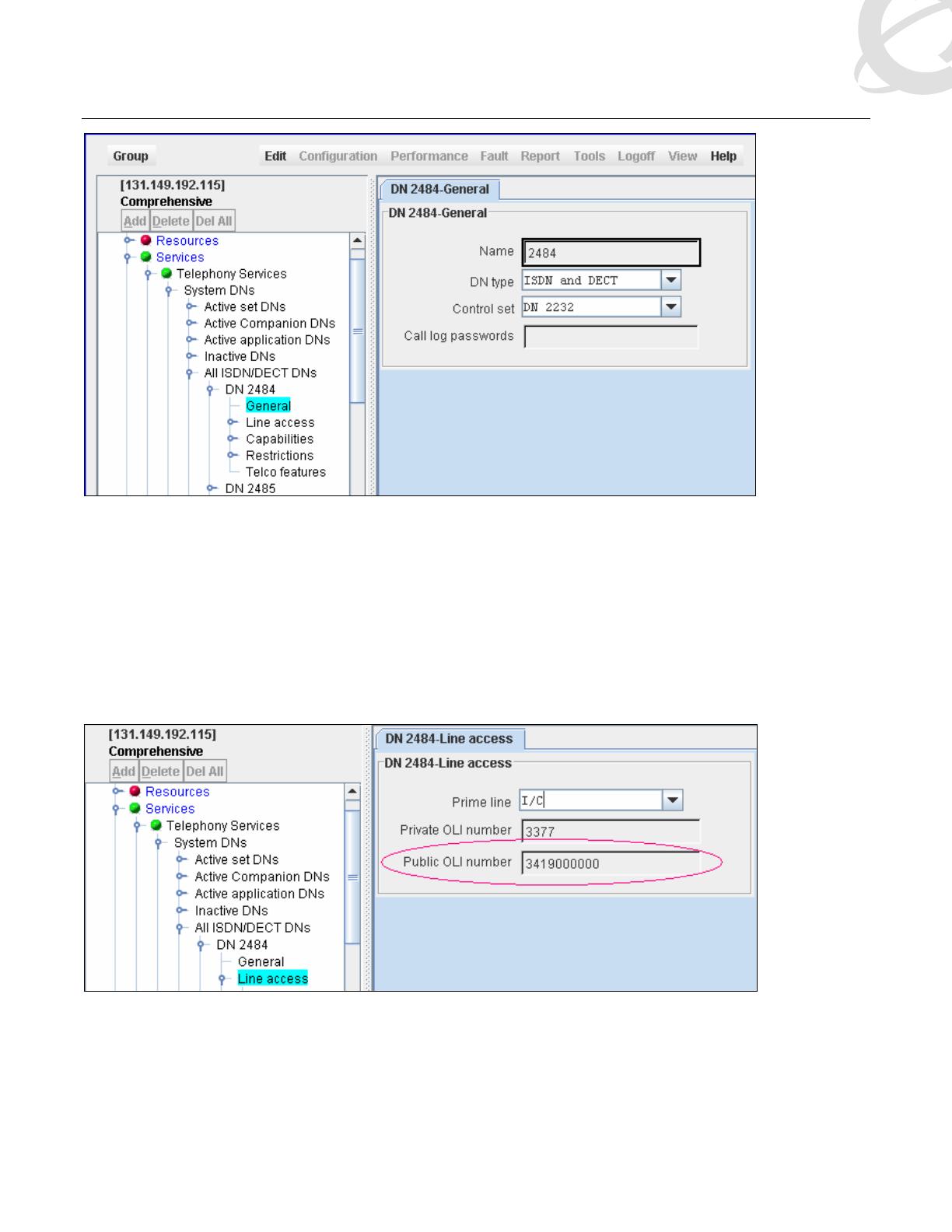
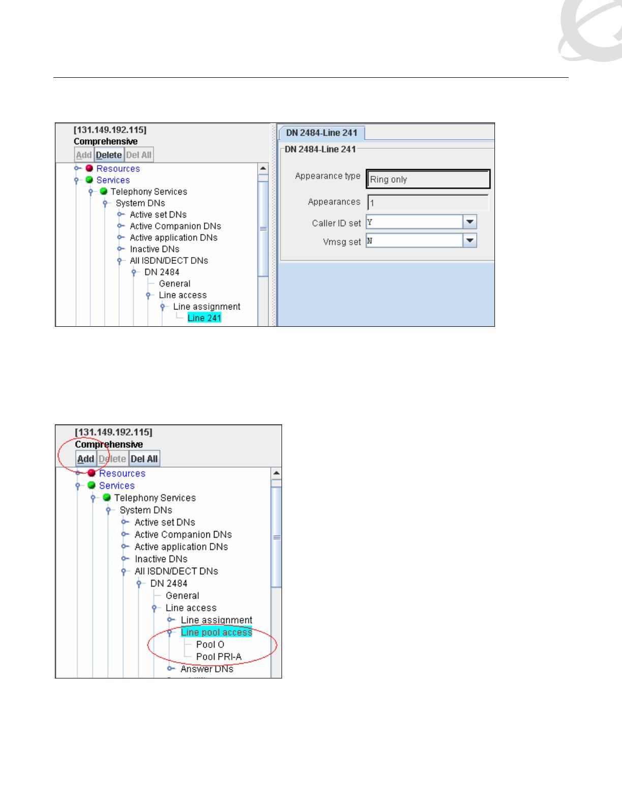
2.4
ISDN DNs.......................................................................................................................................................9
2.5
Loops...........................................................................................................................................................12
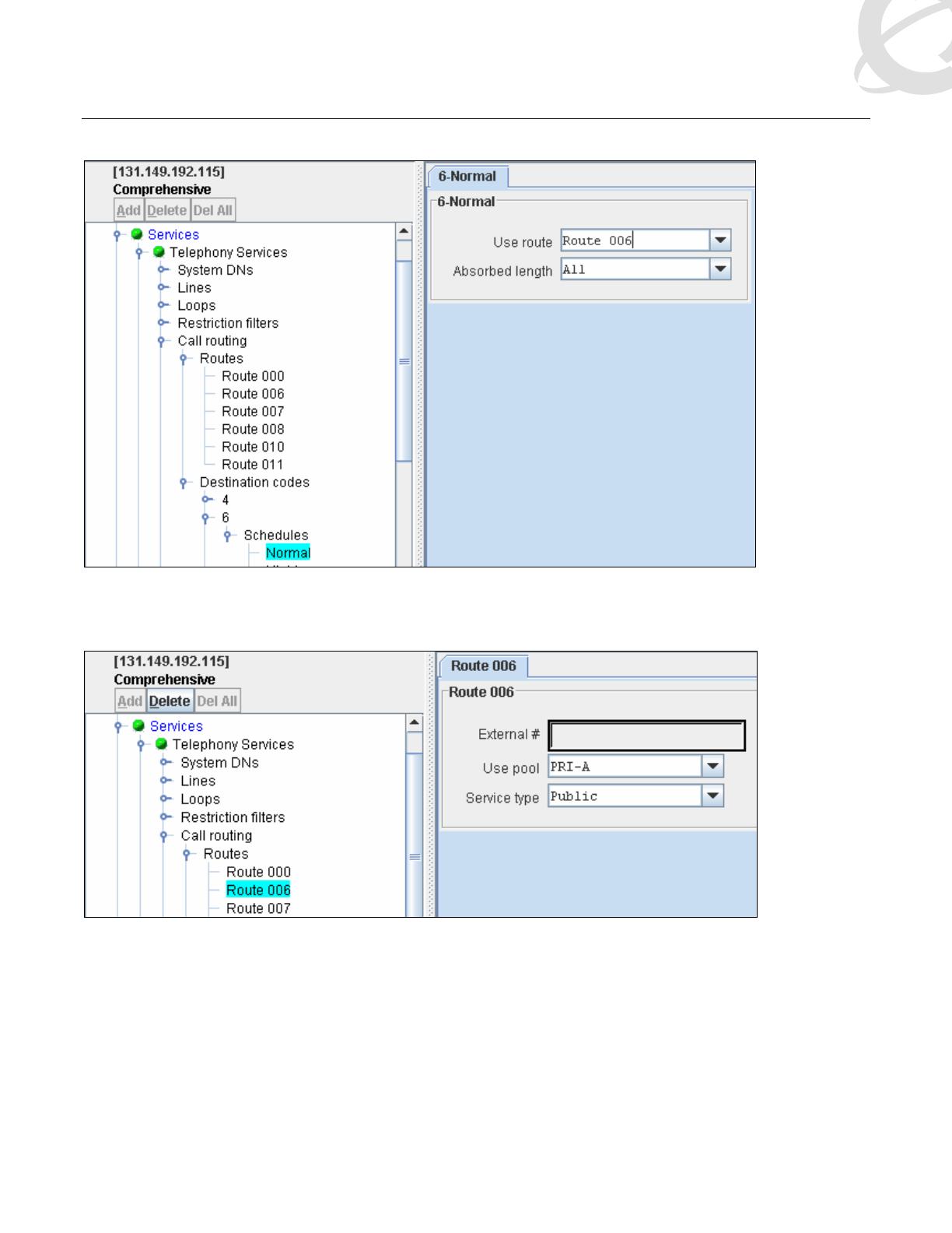
2.6
Routing ........................................................................................................................................................12
2.7
Target Line ..................................................................................................................................................13
2.8
Multiple Loop Setup ...................................................................................................................................14
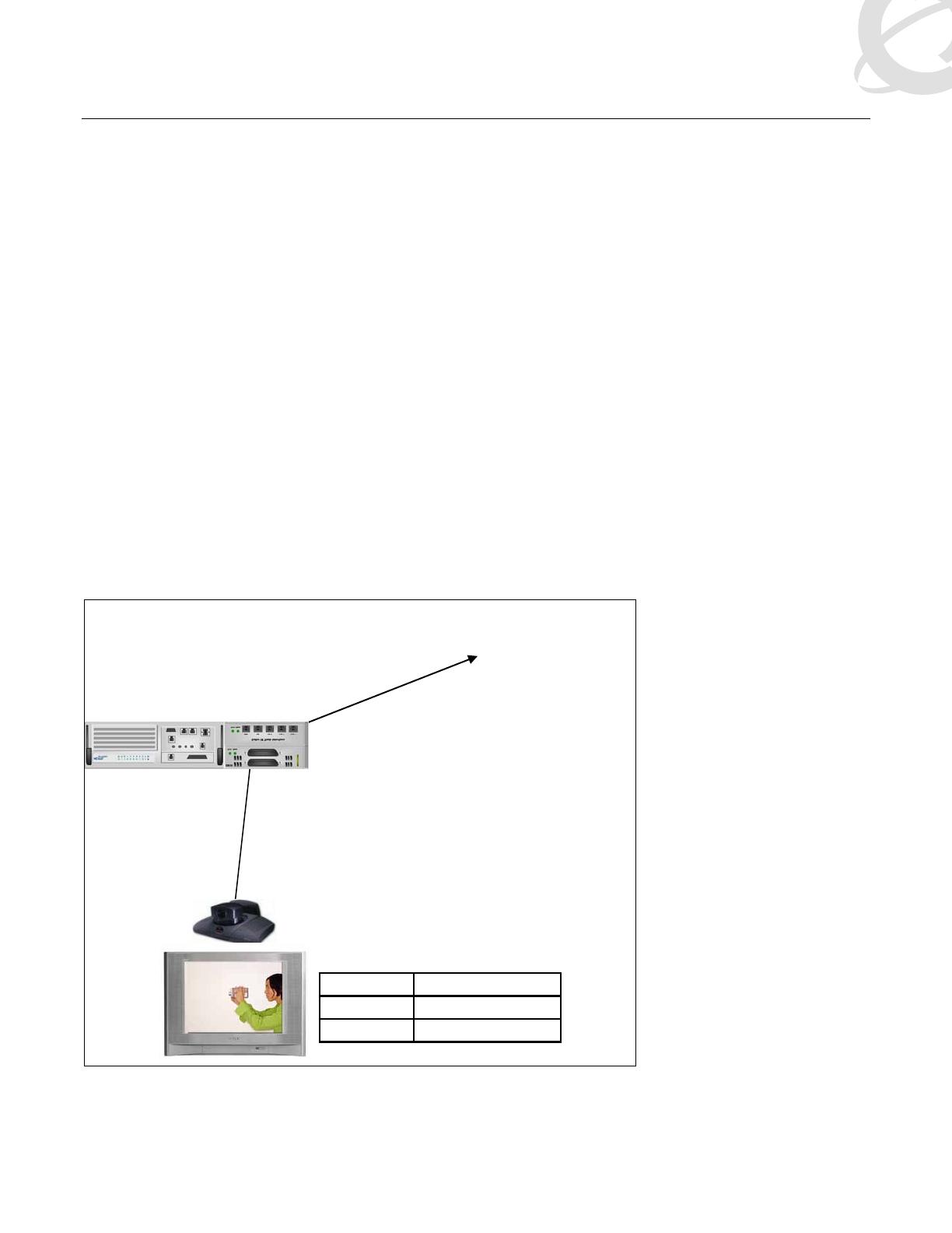
2.9
Polycom.......................................................................................................................................................14
3.
CAVEATS .......................................................................................................................................16
3.1
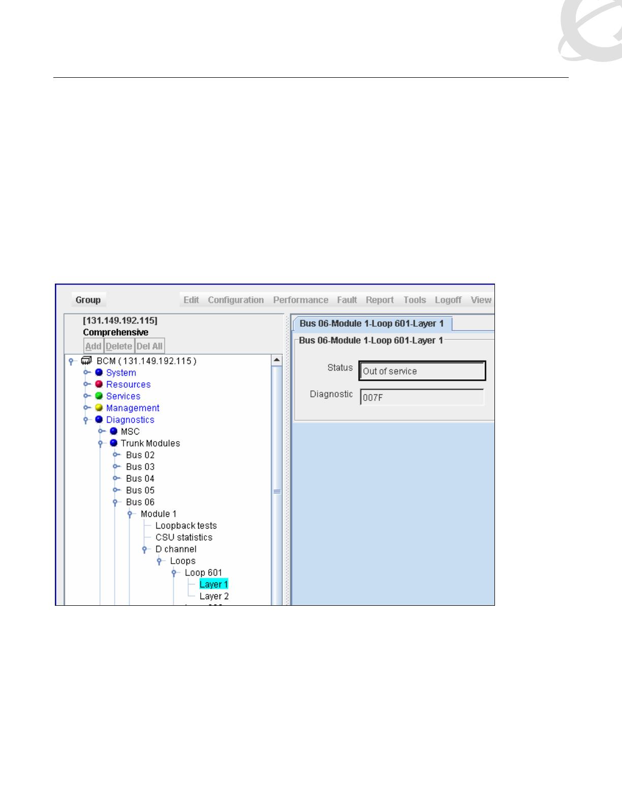
BCM Diagnostics........................................................................................................................................16
3.2
PRI Trunking ...............................................................................................................................................16