Page is loading ...

Thank you for choosing another quality product from Amperes Electronics.
INSTRUCTION MANUAL
LS4808 / LS4816
8 / 16 Speaker Line Surveillance
LS4808 and LS4816 succeeded their predecessor with totally new circuitry providing major improvements over the perfor-
mance, accuracy and reliability. They now comes with 8 and 16 monitoring channels with simplified setting menus. New
measuring algorithms enables measurement of impedance faster with higher accuracy within a narrow tolerance. Another
new feature included is the remote trigger which can be connected to weekly timer to enable monitoring according to the
preset times.
LS line surveillance unit uses impedance measurement method which allows flexibility in speaker cablings such as branching
and does not require end line resistors or blocking capacitors at the speakers. Its RS485 data output enable remote monitor-
ing and controls via customised software or upcoming PMX III Console.
Prior to installation, we suggest a thorough read through of the manual to get a proper understanding of the unit and what it
can offer. We are pretty sure that you are having a premium product at optimum price for your system.
Please keep this manual for future references.
SPEAKER LINE SURVEILLANCE
LS 4816
amperes
PRE
CH 1 CH 2 CH 4CH 3 CH 5 CH 6 CH 7
CH 8
ZONE / SPEAKER CHANNEL
CH 9
CH 10 CH 12CH 11 CH 13 CH 14 CH 15 CH 16
MENU
ENTER
NEXT
SPEAKER LINE SURVEILLANCE
LS 4808
amperes
CH 1 CH 2 CH 4CH 3 CH 5 CH 6 CH 7
CH 8
ZONE / SPEAKER CHANNEL
PRE MENU
ENTER
NEXT

Parts Identifications
PAGE 2 LS4808 / LS4816 | 8 / 16 CHANNEL SPEAKER LINE SURVEILLANCE
1. LCD DISPLAY
3. ENTER / MENU BUTTON
4. NEXT BUTTON
Previous key to scroll back to last menu or sub menu.
2. PREV BUTTON
The green LED indicates the corresponding channel is normal, whereas red indicates that channel is faulty.
5. ZONE / SPEAKER CHANNEL LED INDICATORS
2 x 16 digit LCD display with back light setting is used as programming guide as well as measurement indications.
Menu switch is used to access main menus. Once pressed momentarily, it shall revert to Menu 1.0 - Setup. Use
Next or Prev keys to scroll through other main menus. Once the relevant menu is found, use Enter key to access
its following sub menu. To exit sub menus, press Menu key momentarily.
Next button to shift to next menu sub menu.
1
2 3 4
5
6
7
8
9
10
The unit requires 24V DC power supply and recommended PSU shall be Amperes PS9400. Only use regulated
power supply if other than PS9400 is installed.
6. 24V DC POWER SUPPLY PORT
SPEAKER LINE SURVEILLANCE
LS 4816
amperes
PRE
CH 1 CH 2 CH 4CH 3 CH 5 CH 6 CH 7
CH 8
ZONE / SPEAKER CHANNEL
CH 9
CH 10 CH 12CH 11 CH 13 CH 14 CH 15 CH 16
MENU
ENTER
NEXT
RS485
DATA
A B
FAULT
RELAY
NO
COM
AMP 10ZON 9
COM
COM
100V
100V
COM
100V
ZON 10
100V
AMP 9
100V
COM
ZON 13
COM
AMP 14
100V
100V
AMP 13
100V
COM
100V
ZON 12
COM
COM
ZON 14
COM
ZON 11
100V
AMP 11
COM
100V
COM
AMP 12
100V
AMPLIFIER INPUTS - ZONE OUTPUTS FOR ZONE 9 TO ZONE 16
COM
100V
ZON 16
COM
ZON 15
100V
AMP 15
COM
100V
COM
AMP 16
100V
-
+
DC 24V
TRIGGER
TRIGGER
RELAY
NO
EXT
Quality Product From
AMPERES ELECTRONICS
LS 4816
LINE SURVEILLANCE
COM
AMP 2ZON 1
COM
COM
100V
100V
COM
100V
ZON 2
100V
AMP 1
100V
COM
ZON 5
COM
AMP 6
100V
100V
AMP 5
100V
COM
100V
ZON 4
COM
COM
ZON 6
COM
ZON 3
100V
AMP 3
COM
100V
COM
AMP 4
100V
AMPLIFIER INPUTS - ZONE OUTPUTS FOR ZONE 1 TO ZONE 8
COM
100V
ZON 8
COM
ZON 7
100V
AMP 7
COM
100V
COM
AMP 8
100V
ZONE IN
AMP.1
FAULT O/P CONTACT
AMP.16
EXT TRIGGER
RS485
100V LINE
ZONE 1
ZONE O/Ps
LS4816
ZONE 16
SPEAKERS
TRIG O/Ps
VOL O/RIDE
MAX 3A
DRY CONT

Parts Identifications
PAGE 3LS4808 / LS4816 | 8 / 16 CHANNEL SPEAKER LINE SURVEILLANCE
When line monitoring is initiated either manually or auto, it shall start in sequence from ch.1 to 16. With each channel
under monitoring, a dry contact shall be available. This shall provide 24V overriding voltage to volume controllers or
local patch panel with overriding relay, thus allowing direct measurement to the speakers. (Refer to Connecting the
unit section of the manual). Overriding is required for accurate sensing in which volume controllers set in various
position shall have different impedances and such circumstances shall provide false alarm or alert.
Recommended practice is that every zone shall have its own 24V overriding circuit back to the rack. If all the
overriding circuits are looped, and if the particular zone with volume controller is set to off, the monitoring activity shall
cause a burst of audio signal (such as BGM), which lasted for approximately 18 seconds. This shall happen only
when a BGM source is presence. If the particular zone is set to OFF (without BGM), the monitoring activity shall not
emit audible sound.
7. ZONE TRIGGER OUTPUT PORT
It is for connections of incoming 100V line signal and output to speakers. Refer to Connecting the Unit in following
section.
8. AMP / ZONE IN - OUT PORTS
Whenever a fault condition is detected, this port shall provide a dry contact to link to external alerting devices, such
as mimic panel, etc.
9. OUTPUT FAULT CONTACT
Event triggered data shall be transmitted with RS485 protocol.
10. RS485 OUTPUT (OPTIONAL)

Configuration / Schematic
PAGE 4 LS4808 / LS4816 | 8 / 16 CHANNEL SPEAKER LINE SURVEILLANCE
Zone 1
Speakers Parallel
ZONE 1
RACK MOUNT
ZONE
VOL.CTRL.
SPEAKER
ZONE
SELECTOR
POWER AMPLIFIERS
LS4816
24V DC VOLTAGE
AUDIO SIGNAL
INPUTS NOT
SHOWN
VOLUME
CONTROLLERS /
PATCH PANEL
AUDIO SIGNAL
24V DC OVERRIDING
The LS4808 / 4816 detects circuit faults using impedance measurement method. In general, there is no limitation on how the
external cabling to speakers or volume controller are run, ie. branching is allow and does not need end line resistors as well
as speaker capacitor couplings.
It is recommended that periodical manual checking or setup to be made as connections may deteriorate over time and thus
affecting overall impedance value.
PUBLIC ADDRESS POWER AMPLIFIER
SIGNAL -40 dB
SIGNAL -10 dB
POWER
PROTECT
CLIP
PA 2480
amperes
PUBLIC ADDRESS POWER AMPLIFIER
SIGNAL -40 dB
SIGNAL -10 dB
POWER
PROTECT
CLIP
PA 2480
amperes
ZS5121
OVERRIDE
21 3 54
SPEAKER ZONE SELECT
6 7 8 9 10 1211
CALL
ALL
Zone 2
Direct VC
Zone 3
VC Parallel
Zone 16
SPEAKER LINE SURVEILLANCE
LS 4816
amperes
PRE
CH 1 CH 2 CH 4CH 3 CH 5 CH 6 CH 7
CH 8
ZONE / SPEAKER CHANNEL
CH 9
CH 10 CH 12CH 11 CH 13 CH 14 CH 15 CH 16
MENU
ENTER
NEXT

PAGE 5LS4808 / LS4816 | 8 / 16 CHANNEL SPEAKER LINE SURVEILLANCE
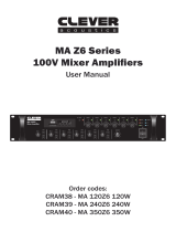
Connecting The Unit
RS485
DATA
A B
FAULT
RELAY
NO
COM
AMP 10ZON 9
COM
COM
100V
100V
COM
100V
ZON 10
100V
AMP 9
100V
COM
ZON 13
COM
AMP 14
100V
100V
AMP 13
100V
COM
100V
ZON 12
COM
COM
ZON 14
COM
ZON 11
100V
AMP 11
COM
100V
COM
AMP 12
100V
AMPLIFIER INPUTS - ZONE OUTPUTS FOR ZONE 9 TO ZONE 16
COM
100V
ZON 16
COM
ZON 15
100V
AMP 15
COM
100V
COM
AMP 16
100V
-
+
DC 24V
TRIGGER
TRIGGER
RELAY
NO
EXT
Quality Product From
AMPERES ELECTRONICS
LS 4816
LINE SURVEILLANCE
COM
AMP 2ZON 1
COM
COM
100V
100V
COM
100V
ZON 2
100V
AMP 1
100V
COM
ZON 5
COM
AMP 6
100V
100V
AMP 5
100V
COM
100V
ZON 4
COM
COM
ZON 6
COM
ZON 3
100V
AMP 3
COM
100V
COM
AMP 4
100V
AMPLIFIER INPUTS - ZONE OUTPUTS FOR ZONE 1 TO ZONE 8
COM
100V
ZON 8
COM
ZON 7
100V
AMP 7
COM
100V
COM
AMP 8
100V
ZONE IN
AMP.1
FAULT O/P CONTACT
AMP.16
EXT TRIGGER
RS485
100V LINE
ZONE 1
ZONE O/Ps
LS4816
ZONE 16
SPEAKERS
TRIG O/Ps
VOL O/RIDE
MAX 3A
DRY CONT
VC override
terminal
(Dry contact only)
Ext trigger for
manual / times
activation
Amp - zone
connections
RS485
Fault dry contact
Programming And Setup
In general, there are 5 main menus as shown below:
MAIN MENU
1. SETUP
2. MANUAL TEST
3. AUTO TEST
4. SYSTEM
POWER UP
TO ENTER SETUP
NOTE :
PRE MENU
ENTER
NEXT
Upon powering for the first time, the unit shall display wordings ‘ Speaker Line
Surveillance’. The red LEDs shall lit in sequence indicating sequence of initiali-
sation.
Minimum setup required for the system to run shall be Menu 1.0. If other menus are not set, they shall run according to default
parameters.
To begin programming, press MENU button, and the SETUP menu shall be
displayed.
5. SAVE & EXIT
EXT
TRIGGER
TRIGGER
RELAY
NO
+24V
VC1
0V
VC2
0V

PAGE 6 LS4808 / LS4816 | 8 / 16 CHANNEL SPEAKER LINE SURVEILLANCE
1. Setup Menu
BASIC SETUP
There are 2 modes of operation available : Basic and Advance.
In Basic setup mode, LS4808 / 4816 shall detect the circuit for circuit fault automatically. The timing of detection shall depend
on the intervals set in Auto Detection mode, ( Refer to Auto Test section ). Follow the steps below to use this mode.
EXIT
MAIN MENU
ENTER
>
1. SETUP
ENTER
>
CHANNEL 01: IMPEDANCE
MONITORED / BYPASS
ENTER to confirm or press PREV/NEXT button untill EXIT option show up
then press ENTER to EXIT.
>
1. SETUP
1. BASIC SETUP
PREV
>
NEXT
>
CHANNEL 01: IMPEDANCE
MONITORED
CHANNEL 01: IMPEDANCE
BYPASS
Press Next / Prev button to switch the Channel
>
ADVANCE SETUP
MAIN MENU
ENTER
>
1. SETUP
ENTER
>
CHANNEL 01: XXX Ω
MONITORED
ENTER to confirm & press NEXT for setting another channel
or press PREV button for EXIT
1. SETUP
2. ADVANCE SETUP
PREV
>
NEXT
>
CHANNEL 01: XXX Ω
MONITORED
CHANNEL 01: XXX Ω
>BYPASSED
>
CHANNEL 01: XXX Ω
LOW LIMIT: 0005Ω
>
CHANNEL 01: XXX Ω
HIGH LIMIT: 0010Ω
>
Press Next / Prev button to select impedence limit.
NEXT
>
1. SETUP
2. ADVANCE SETUP
NEXT
>
Note: In long cable circuit or zone with multiple branchings the basic mode may not be suitable to detect the fault such as short
at the far end of cable (e.g: 500m), cables itself has resistance, thereby would not show short phenomena. It is therefore,
Advance setup shall be used.
Note: The unit shall measure the impedance of each channel, creating the high and low limits automatically. Whenever the
measured impedance falls outside the limits, the channel shall be considered faulty. The limits are typically 15%, eg if the circuit
has impedance of 1K Ω, the limits generated shall be 850 to 1.15K Ω.
Refer to
Advanced Setup
Fault Detection: Open : +/- 15% from measured impedance
Press Enter to confirm setting
& Next / Prev button to switch the Channel
Press Enter to allow LS to
perform a impedance limits
calibration. NEXT/PREV button
to switch the channel.
ENTER
1. SETUP
1. BASIC SETUP
NEXT
>
CHANNEL 02: XXX Ω
MONITORED
CHANNEL 01: XXX Ω
MONITORED / BYPASS
ENTER
>
Press Next / Prev button to
switch the Channel
EXIT
>
PREV
Press Next / Prev button to select impedence limit.
ENTER
>
ENTER for save the
setting
CHANNEL 01: XXX Ω
BYPASSED
PREV
>
>
NEXT for setting another channel
CHANNEL 02: XXX Ω
MONITORED
Refer to Basic Setup
EXIT

PAGE 7LS4808 / LS4816 | 8 / 16 CHANNEL SPEAKER LINE SURVEILLANCE
1. Setup Menu
1. SETUP
ENTER
>
BUZZER
ENABLE / DISABLED
3. BUZZER
NEXT
>
BUZZER
DISABLED
PREV
>
BUZZER
ENABLE
Buzzer is available for button pressing and alert / fault signal. This feature can be turned off to fit to ones' preference.
For fault alert buzzer, if this is switch on, the Buzzer LED shall not lit when a failure is detected. If the buzzer is
switched off, the buzzer LED and the correspondence channel fault LED shall lit.
ENTER to confirm ENABLE / DISABLE buzzer.
>
1. SETUP
1. BASIC SETUP
PREV
>
1. SETUP
5. EXIT
1. SETUP
ENTER
>
CHANNEL 01
BP FAULT: YES / NO
4. CH BP ON FAULT
NEXT
>
PREV
>
ENTER to confirm YES / NO.
>
1. SETUP
1. BASIC SETUP
CHANNEL 01
BP FAULT: NO
CHANNEL 01
BP FAULT: YES
BUZZER
CH BP ON FAULT
NEXT
>
1. SETUP
5. EXIT
NEXT
>
1. SETUP
4. CH BP ON FAULT
Press Next / Prev button to switch the Channel
Note: The unit shall measure the impedance of each channel, creating the high and low limits automatically. Whenever the
measured impedance falls outside the limits, the channel shall be considered faulty. The limits are typically 15%, eg if the
circuit has impedance of 1K Ω, the limits generated shall be 850 to 1.15K Ω.
>
>

PAGE 8 LS4808 / LS4816 | 8 / 16 CHANNEL SPEAKER LINE SURVEILLANCE
2. Manual Test
MAIN MENU
3. AUTO TEST
MAIN MENU
ENTER
>
3. AUTO TEST
ENTER
>
3. AUTO TEST
INTERVAL: 01 MIN
ENTER
>
3. AUTO TEST
ENABLE / DISABLED
PREV
>
NEXT
>
3. AUTO TEST
ENABLE
3. AUTO TEST
DISABLED
Press Next / Prev button to select ENABLED / DISABLED
If a test interval is selected ( from 1 min - 24 hour ). By default, auto mode is set to off.
Use NEXT / PREV button to select time.
3. Auto Test
MAIN MENU
ENTER
>
2. MANUAL TEST
BEGIN: YES / NO
2. MANUAL TEST
Press Next / Prev button to select YES / NO
Use this function to test speaker line impedance of each channel.
ENTER
>
>
If NO is selected
Return to menu 2. MANUAL TEST
If YES, the Test is started

PAGE 9LS4808 / LS4816 | 8 / 16 CHANNEL SPEAKER LINE SURVEILLANCE
4. System
MAIN MENU
ENTER
>
4. SYSTEM
NEXT
>
4. SYSTEM
2. MODEL
NEXT
>
4. SYSTEM
1. ADDRESS
Press Next / Prev button to switch the
Address (from 001 to 254) and then
ENTER to set the ADDRESS and go
to next MENU
011
LS4816
To show the Model
4. SYSTEM
3. FIRMWARE
V1.03
To show the Firmware
NEXT
>
4. SYSTEM
4. EXIT
ENTER
>
MAIN MENU
4. SYSTEM
Return to MAIN MENU
NEXT
>
MAIN MENU
5. SAVE & EXIT
After completing all setting, the
changed parameters MUST be
saved.
LS4808 / 4816 are used to detect faulty speaker circuits and the impedance measured shall not be used as final
value / reading as conclusions. The actual reading may differ from actual impedance meter in range of 5%.
IMPORTANT NOTES

PAGE 10 LS4808 / LS4816 | 8 / 16 CHANNEL SPEAKER LINE SURVEILLANCE
Notes On Speaker Line Impedance
In reality, impedance of a speaker circuit consists of Resistance (normally cable) and Capacitive reactance and Inductive
reactance.
Z = R + Inductive Reactance + Capacitive Reactance
Using a multimeter (pure resistance measurement) to measure a speaker circuit is not the accurate tool to determine the
value to calculate the total load of the line, which they are not capable to measure the Capacitive or Inductive reactance
of cable and speaker coils.
In circuit with branching, a break at point would not trigger an ‘open circuit’ alarm, and a short at point would not
trigger ‘short circuit’ indication as these still exist some impedance due to cable resistance.
LS4808 / 4816 has unique way to detect faults, there by using basic mode, creating an impedance limit range and for
more sensitive detection, set the unit to ‘advance’ mode.
A B
B
A
A
Impedance
meter
▲ ▲
----
▲
Ø
▲
Branch
R
L / C L / C
VC
--

Technical Specifications
PAGE 11LS4808 / LS4816 | 8 / 16 CHANNEL SPEAKER LINE SURVEILLANCE
Summary Of Features
■
■
■
■
■
■
■
■
■
■
■
■
Note:
The above specifications are correct at time of printing but subjected to changes without prior notice due to product
improvements.
8 / 16 channel speaker line monitoring and expandable
Basic and Advance level of detection setup
Detection of faulty cable and speaker in individual zone or circuit
Impedance measurement method - no capacitor coupling required and cable branching allowed.
Faulty circuit disconnection option
Built in impedance meter, range within 10 Ohm to 10 K Ohm
LCD display to facilitate system setup, measurement and monitoring
Fault alert with LED indicators and switchable buzzer
Detection test interval setting from 1 min to 48 hours
Short burst test signal, minimizing interruption to PA operation
User setting for detection sensitivity for open, short and leakage
Aux 24V DC output for volume controller overriding during testing mode
LS4808 LS4816
24V DC via PS9400 adaptor
3.8W
10 to 1000W 100V line
1 KHz
5V sine
0.5 second per channel (max)
User preset from 1 min to 48 hrs
Continuous buzzer with Off option
3A
482 x 44 x 180 mm
2.20kg
4.9W
5% within range
User preset at each channel
3.25kg
STM 32 microprocesser
8
10 to 10 K Ohm
Normal, Fault, Buzzer, Auto run
Operating voltage
Power consumption
Capacity (channel)
Processor
Impedance detection range
Power measurement range
Measurement accuracy
Pilot tone injection frequency
Pilot tone signal output level
Monitor triggering
Transmittal detection period
Detection interval
Sensitivity setting
Indicators - LED
Display LCD
Audible output signal
Dry contact setting
DC output in detection mode
Dimensions (W x H x D)
Weight
2 x 16 characters w back light
24V DC
16
482 x 88 x 180 mm
Auto / remote trigger

Warranty Conditions
Disclaimer
AMPERES ELECTRONICS SDN BHD
MADE IN MALAYSIA
Published : JANUARY 2020
ISO 9001: 2015
Design & Manufacture of Public Address Equipment and Systems
Certicate No. 16895 / A / 0001 / UK / En
Information contained in this manual is subject to change without prior notice and does not represent a commitment
on the part of the vendor. AMPERES ELECTRONICS SDN BHD shall not be liable for any loss or damages
whatsoever arising from the use of information or any error contained in this manual.
It is recommended that all services and repairs on this product be carried out by AMPERES ELECTRONICS SDN
BHD or its authorized service agents.
AMPERES series must only be used for the purpose they were intended by the manufacturer and in conjunction
with this operating manual.
AMPERES ELECTRONICS SDN BHD cannot accept any liability whatsoever for any loss or damages caused by
service, maintenance or repair by unauthorized personnel, or by use other than that intended by the manufacturer.
AMPERES ELECTRONICS SDN BHD
Only Amperes Electronics Service Centres are allowed to make warranty repairs : a list of Amperes Electronics
Service Centres may be asked for by the purchaser or send directly to Amperes Electronics Sdn Bhd at 70 Jalan
Industri PBP 3, Tmn Perindustrian Pusat Bandar Puchong, 47100, Puchong, Selangor, Malaysia or its authorized
dealers. This warranty is not valid if repairs are performed by unauthorized personnel or service centres.
This warranty covers only repairs and replacement of defective parts ; cost and risks of transportation as well as
removal and installation of the product from the main system are for the account of the purchaser. This warranty
shall not extend to the replacement of the unit.
This warranty does not cover damages caused by misuse, neglect, accident of the product as well as using the
product with power supply voltage other than shown on the product, or any other power supply source / adaptor not
recommended by the manufacturer.
This warranty does not cover damages caused by fire, earthquakes, floods, lightning and every cause not directly
related to the unit.
This warranty does not include any indemnity in favor of the purchaser or the dealer for the period out of use of the
unit; moreover the warranty does not cover any damages which may be caused to people and things when using
the product.
This warranty certificate is valid only for the described product, and is not valid if modifications are made on this
certificate or on the identification label applied on the product.
This warranty covers all the material and manufacturing defects and is valid for a period of 36 months from the date
of purchase or for a specified period in countries where this is stated by a national law. In this case, the extension is
valid only in the country where the product is purchased.
Amperes Electronics Sdn Bhd is not obliged to modify previously manufactured products under warranty if the
design changes or improvements are made.
/