Page is loading ...

VC8000 Series
100V LINE SPEAKER VOLUME CONTROLLERS
Thank you for selecting another fine product from Amperes.
VC8000 succeeded the popular VC7000 series with new slimmer facial
outlooks, fitting the contemporary architectural need in any installations. Apart
from that, the unit has been reconstructed to withstand damaging factors such
as drops and improper installations.
The new " slip contour " of the rotary knob has a great purpose - to eliminate
potential abuse during rotation, which could overturn the knob and cause
damage to the unit and possibility to the power amplifiers.
Installing this unit shall not be difficult but a thorough read through of this
manual is recommended in order to avoid any undesired results and also to
tap the full potential of what this unit could offer.
Please keep this manual for future references.
by amperes electronics
www.ampereselectronics.com
PARTS IDENTIFICATIONS
installation manual
Back Enclosure
Back enclosure is available as optional item
which is sold separately.
The recommended depth of back enclosure
shall be about 50 - 60 mm between the finish
surface of the wall and the back surfaceof the
box. Standard electrical back box when used
must be embedded to the wall with the
required depth.
Surface mount back enclosure is also
available with white finishing.
VC Module
The VC module comprises of mounting bracket and the electronic parts
assembled together. Incoming cabling from power amplifier and to
speaker points is connected to this module.
Module is available in several range of power rating : from 5 watts to 50
watts 100V line. Ensure correct power rating for the appropriate load.
Front Plate
The ABS front plate shall be mounted to the VC module
by inserting the pins to the appropriate mounting hole of
the mounting bracket. Standard colour available is off
white
Rotary Knob
This knob shall be the last item to be
installed to the spindle of the rotary switch.
The slip grip contour design reduces the
potential overturn of the unit which could
damage the volume controller as well as
possible damage to the power amplifier.
INSTALLATION PROCEDURES
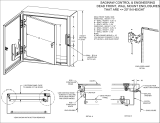
1. Connect Cables
Cables from amplifier, to speakers and the overriding
24V DC shall be connected to the module before
mounting to the back enclosures.
Recommended cable size shall not be more than 2.5mm
sq.
VC Module
Rear view of module .. transformer at top
to speaker
(100V)
from amp
(100V)
common
(amp &
speaker
+24V
DC
-24V DC
for overriding signal
Back enclosure -
surface or wall
concealed
Cable connections not shown
M3X20 mm screw
supplied
VC Module
2. Install VC Module to Back Enclosure
Install the cabled VC module to the back enclosure using
M3 screw provided.
For ease of installation, please do not allow too lengthy
cables which may also cause damage to the VC module
during installation.
Pg 1

by amperes electronics
www.ampereselectronics.com
Only Amperes Electronics Service Centres are allowed to make warranty repairs: a list of Amperes
Electronics Service Centres may be asked for by the purchaser or send directly to Amperes Electronics
Sdn Bhd at 70 Jalan Industri PBP3, Tmn Perindustrian Pusat Bandar Puchong 47100 Puchong or
through its authorised distributors in your region. This warranty is not valid if repairs are performed by
unauthorised personnel or service centres.
This warranty covers only repairs and replacement of defective parts; cost and risks of transportation as
well as removal and installation of the product from the main system are for the account of the purchaser.
This warranty shall not extend to the replacement of the unit.
This warranty does not cover damages caused by misuse, neglect, accident of the product as well as
using the product with power supply voltage other than shown on the product, or any other power
source/adaptor not recommended by the manufacturer.
This warranty does not cover damages caused by fire, earthquakes, floods, lighting and every cause not
directly related to the unit.
This warranty does not include any indemnity in favour of the purchaser or the dealer for the period out of
use of the unit; moreover the warranty does not cover any damages which may be caused to people and
things when using the product.
This warranty certificate is valid only for the described product, and is not valid if modifications are made
on this certificate or on the identification label applied on the product.
This warranty covers all the material and manufacturing defects and is valid for a period of 12 months
from the date of purchase or for a longer period in countries where this is stated by a national law. In this
case, the extension is valid only in the country where the product is purchased.
Amperes Electronics Sdn Bhd is not obliged to modify previously manufactured products under warranty
if the design changes or improvements are made.
Information contained in this manual is subject to change without prior notice and does not
represent a commitment on the part of the vendor. AMPERES ELECTRONICS SDN BHD shall
not be liable for any loss or damages whatsoever arising from the use of information or any
error contained in this manual.
It is recommended that all services and repairs on this product be carried out by AMPERES
ELECTRONICS SDN BHD or its authorised service agents.
AMPERES series must only be used for the purpose they were intended by the manufacturer
and in conjunction with this operating manual.
AMPERES ELECTRONICS SDN BHD cannot accept any liability whatsoever for any loss or
damages caused by service, maintenance or repair by unauthorised personnel, or by use
other than that intended by the manufacturer.
SCHEMATIC DIAGRAM
TERMS AND CONDITIONS OF WARRANTY
DISCLAIMER
Pg 2
INSTALLATION (CON'T)
2. Install Front Panel
Install the front panel with the 4 locking pins inserted to
the mounting bracket of the VC module. Also ensure that
the LED is properly aligned to the LED indicator aperture.
installed VC Module and
back enclosure.
LED indicator
aperture
insert locking
pins to the
VC module
bracket via
the 4 holes.
As shown
3. Install Switch Knob
Follow the 3 steps below when installing the switch knob.
A. Turn the switch shaft
counter clock wise till the
end, the OFF position
B. Align the OFF
position at the plate
with the marker of the
knob before insert it to
the switch shaft as
shown.
switch knob
wall
switch shaft
front plate
C. Once the alignment of
the knob marker and OFF
position is confirmed, push
the knob fully towards the
shaft.
SPECIFICATIONS
switch shaft
knob marker
24V DC OVERRIDING SIGNAL
100V LINE AUDIO SIGNAL
SPEAKERS
LOOP TO NEXT POINTS
OPTIONAL
AMPLFIER
PAGING MIC /
OTHER INPUTS
VC8000
Note :
Use appropriate cable size for ease of termination
at the volume controller or the patch panel.
Optional local speaker patch panel shall be
installed before volume controller.
Spe a k e r
p a t c h
panel
Variants of Model
Overriding voltage
Overriding current
Attenuation / step
Size of plate
Weight
Optional item :
Concealed back encl
Surface back encl
VC8005 - 5W 100V Resistive
VC8010 - 10W 100V Auto trans
VC8030 - 30W 100V Auto trans
VC8050 - 50W 100V Auto trans
24V DC
15 mA
-6 dB
86 x 86 mm
VC8005 - 200 gms
VC8010 - 250 gms
VC8030 - 255 gms
VC8050 - 275 gms
72(W) x 72(H) x 60(D) mm : rainbow plated
85(W) x 85(H) x 60(D) mm : white
Recommended back enclosure is 60 mm.
For standard electrical back enclosure,
ensure that the depth to be appr.60 mm
from the finished wall surface.
/