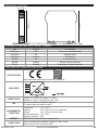
Seneca Z-D-IN is a versatile device capable of monitoring inputs and transmitting data over a Modbus network. It features five inputs that can be configured to accept a variety of signals, including reed, contact, and proximity PNP/NPN. With input 5 capable of high-frequency counting at 10 kHz, the Z-D-IN excels in applications requiring precise monitoring of rapidly changing signals. Its Modbus connectivity allows for seamless integration into industrial automation systems, enabling remote monitoring and control.
Seneca Z-D-IN is a versatile device capable of monitoring inputs and transmitting data over a Modbus network. It features five inputs that can be configured to accept a variety of signals, including reed, contact, and proximity PNP/NPN. With input 5 capable of high-frequency counting at 10 kHz, the Z-D-IN excels in applications requiring precise monitoring of rapidly changing signals. Its Modbus connectivity allows for seamless integration into industrial automation systems, enabling remote monitoring and control.


-
 1
1
-
 2
2
-
 3
3
-
 4
4


Seneca Z-D-IN is a versatile device capable of monitoring inputs and transmitting data over a Modbus network. It features five inputs that can be configured to accept a variety of signals, including reed, contact, and proximity PNP/NPN. With input 5 capable of high-frequency counting at 10 kHz, the Z-D-IN excels in applications requiring precise monitoring of rapidly changing signals. Its Modbus connectivity allows for seamless integration into industrial automation systems, enabling remote monitoring and control.
Ask a question and I''ll find the answer in the document
Finding information in a document is now easier with AI
Related papers
-
Seneca ZE-4DI Digital Output Modbus Installation guide
-
Seneca VPN BOX 2 User manual
-
-
Seneca Z-8AI User manual
-
-
Seneca Z-KEY-WIFI Installation guide
-
Seneca Z-KEY-2ETH Installation guide
-
Seneca Z109S-DI User manual
-
Seneca Z-LTE-WW Installation guide
-
Seneca Z-KEY Installation guide
Other documents
-
Metronic DL2 Operating instructions
-
Danfoss VLT Micro Drive FC 51 User guide
-
 Logicbus Convert AC/DC Current to RS485 Modbus Installation guide
-
 Masibus MINT Communication Processor User manual
-
Schneider Electric Modicon M171 - Performance Logic Controller, Hardware User guide
-
 Santerno Sinus Penta User manual
-
red lion PAXDR User manual
-
TECO TP03 PLC User manual
-
 ADTEK CS2-CT User manual
-
ProSoft Technology PLX51-DNPS User manual


