Seneca Z-KEY-WIFI Installation guide

Type
Installation guide

Seneca Z-KEY-WIFI is a gateway module and serial device server with Wi-Fi capabilities, allowing for flexible data transmission and communication in various industrial applications. Its compact design and DIN rail mounting make it easy to integrate into existing systems. With built-in RS485 and RS232 serial ports, Z-KEY-WIFI can connect to a wide range of industrial devices, enabling remote monitoring and control. Additionally, the Ethernet port and Wi-Fi connectivity provide versatile networking options for data transmission over wired or wireless networks.

Seneca Z-KEY-WIFI is a gateway module and serial device server with Wi-Fi capabilities, allowing for flexible data transmission and communication in various industrial applications. Its compact design and DIN rail mounting make it easy to integrate into existing systems. With built-in RS485 and RS232 serial ports, Z-KEY-WIFI can connect to a wide range of industrial devices, enabling remote monitoring and control. Additionally, the Ethernet port and Wi-Fi connectivity provide versatile networking options for data transmission over wired or wireless networks.

INSTALLATION MANUAL
Z-KEY-WIFI
Gateway Module /Serial Device Server with WIFI
SENECA s.r.l.
Via Austria, 26 – 35127 – PADOVA – ITALY
Tel. +39.049.8705355 - 8705359 - Fax +39.049.8706287
For manuals in other languages and the conguration software, visit www.seneca.it/products/z-key-wi
EN
MI00544-2-EN 1/7
DOCUMENTATION
MODULE LAYOUT
LED STATUS LED meaning
PWR Green ON The device is powered correctly
SD Red Flashing Accessing the microSD card
TX1 Red Flashing Data transmission on port #1 RS485
RX1 Red Flashing Data receipt on port #1 RS485
TX2 Red Flashing Data transmission on port #2 RS485/RS232
RX2 Red Flashing Data reception on port #2 RS485/RS232
ETH ACT Green Flashing Packet transmission on Ethernet port
ETH ACT Green ON No activity on Ethernet port
ETH LNK Yellow ON Ethernet connection present
ETH LNK Yellow Off No Ethernet connection
4 LED On Signal strength (0 = min. / 4 = max.)
AP On Access Point mode active
AP Flashing Access Point mode rst conguration
ST On Station mode active
SIGNALS VIA LED ON FRONT PANEL
2/7
mm
35
mm
111
mm
102.5
Dimensions: LxHxD 35 x 102.5 x 111; Weight:: 220 g; Enclosure: PA6, Black
WARNING: The full content of this manual must be read before any operation. The module must only be used by
qualied electricians. Specic documentation is available via QR-CODE shown on page 1.
Electrical and electronic waste disposal (applicable in the European Union and other countries with recycling).
The symbol on the product or its packaging shows the product must be surrendered to a collection centre
authorized to recycle electrical and electronic waste.
The module must be repaired and damaged parts replaced by the Manufacturer. The product is sensitive to
electrostatic discharges. Take appropriate measures during any operation.
PRELIMINARY WARNINGS
The word WARNING preceded by the symbol indicates conditions or actions that put the user's safety at risk.
The word ATTENTION preceded by the symbol indicates conditions or actions that might damage the
instrument or the connected equipment. The warranty shall become null and void in the event of improper use or
tampering with the module or devices supplied by the manufacturer as necessary for its correct operation, and if
the instructions contained in this manual are not followed.
TECHNICAL SPECIFICATIONS
STANDARDS
Safety: EN60950, EN62311
Radio equipment device: EN301489-1 V2.1.1, EN301489-17 V3.1.1, EN300328 V2.1.1
Additional notes: a 1 A delayed fuse must be installed near the module, in series with the
power supply connection.
INSULATION
ENVIRONMENTAL
CONDITIONS
Temperature: -25 – + 65 °C
Humidity: 30%– 90% non condensing.
Altitude: Up to 2000 m above sea level
Storage temperature: -30 – + 85 °C
Protection rating: IP20 (Not evaluated by UL)
ASSEMBLY IEC EN60715, 35mm DIN rail in vertical position.
CONNECTIONS
3-way removable screw terminals, pitch 5 mm
Rear connector IDC10 for DIN bar 46277
RJ45 front connector
SMA antenna connector
front micro USB
microSD card slot
POWER SUPPLY Voltage: 11 – 40 Vdc; 19 – 28 Vac 50 – 60 Hz
Absorption: Max. 3,8W
WIFI IEEE 801.11 b/g/n
Security WEP / WPA / WPA 2
COMMUNICATION
PORTS
RS242 or RS485 switchable on terminal 10 - 11 - 12: Maximum baud rate 115 k, maximum
RS232 cable length <3m, ModBus RTU master / modBus RTU slave protocol.
RS485 IDC10 rear connector: Maximum baud rate 115 k, ModBus RTU master / ModBus
RTU slave protocol.
RJ45 front Ethernet connector: 100 Mbit/s, maximum distance 100 m
Micro SD: plug-in: lateral micro USB
FACTORY IP ADDRESS
3/7
The default module IP address is static: 192.168.90.101
WEB SERVER
To access the maintenance Web Server with 192.168.90.101 factory IP address:
Default user: admin, Default password: admin, http://192.168.90.101
Power
Supply
1500 Vac
ETH
USB
Comm.
Comm. RS485
RS485/232
(IDC10)
WIFI
The device may only be powered by a power supply unit with a limited energy electric circuit max.
40Vdc / 28Vac Max output in accordance with CAN/CSA-C22.2 No. 61010-1-12 / UL Std. No. 61010-1 (3rd
Edition) chapter 6.3.1/6.3.2 and 9.4 or class 2 according to CSA 223/UL 1310.
ATTENTION
INSTALLATION REGULATIONS
The module has been designed for vertical installation on a DIN 46277 rail. For optimal operation and long life,
adequate ventilation must be provided. Avoid positioning ducting or other objects that obstruct the ventilation slots.
Avoid mounting modules over heat-generating equipment. Installation in the bottom part of the electrical panel is
recommended.
Guida DIN
MODULO
Inserimento nella
guida DIN
Insertion in the DIN rail
As shown in gure:
1. Insert the IDC10 rear connector of the module on a
free slot of the DIN rail (the insertion is univocal since
the connectors are polarized).
2. To secure the module to the DIN rail, tighten the two
hooks on the sides of the IDC10 rear connector.
USB PORT
CU MICROO TG-A CU MICROB-A-
CU MICROB-A-
Configurazione
tramite APP
Android
Configurazione
tramite
software PC
The module is designed to exchange data according to the modes dened by the MODBUS protocol. It has a micro
USB connector on the front panel and can be congured using applications and/or software programs.
The USB serial port uses the following communication parameters: 115200,8,N,1
The USB communication port responds exactly like the serial ports, with the exception of the communication
parameters.
For more information, visit www.seneca.it/products/z-key-wi
Check that the device in question is included in the list of products supported by the Easy Setup APP in the store.
4/7
SETTING THE DIP-SWITCHES
RS232/RS485 SETTING: RS232 or RS485 conguration on terminals 10-11-12 (serial port 2)
SW2
1 ON RS232 ACTIVATION
0 OFF RS485 ACTIVATION
SETTINGS OF FACTORY PARAMETERS
This procedure returns the IP to the factory one (192.168.90.101) and the Web Server/
FTP server access credentials to user: admin and password: admin.
1. Turn the Z- KEY WIFI module off and set all eight SW1 DIP-switches ON.
2. Turn on the Z-KEY WIFI module and wait 10 seconds.
3. Turn the Z- KEY WIFI module off and set all eight SW1 DIP-switches OFF.
KEY
1 ON
0 OFF
- -
Insertion in the
DIN rail MODULE
DIN rail
Android APP
conguration
PC software
conguration
These are open-type devices and intended for installation in an end enclosure / panel offering mechanical
protection and protection against spread of re.
ATTENTION
5/7
ELECTRICAL CONNECTIONS
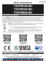
Power supply and Modbus interface are available using the Seneca DIN rail bus, via the IDC10 rear connector, or
the Z-PC-DINAL-17.5 accessory.
RS485 GND
RS485 A
RS485 B
Power Supply AC / +
Power Supply AC / -
IDC 10
1
Back connector (IDC 10)
The illustration shows the meanings of the various
IDC10 connector pins if signals are to be sent via
them directly.
Power Supply AC
Ground
Power Supply AC
GNDSHLDG ND
CANL / BCANL / A
DIP SWITCH
(1230 Ohm terminator)
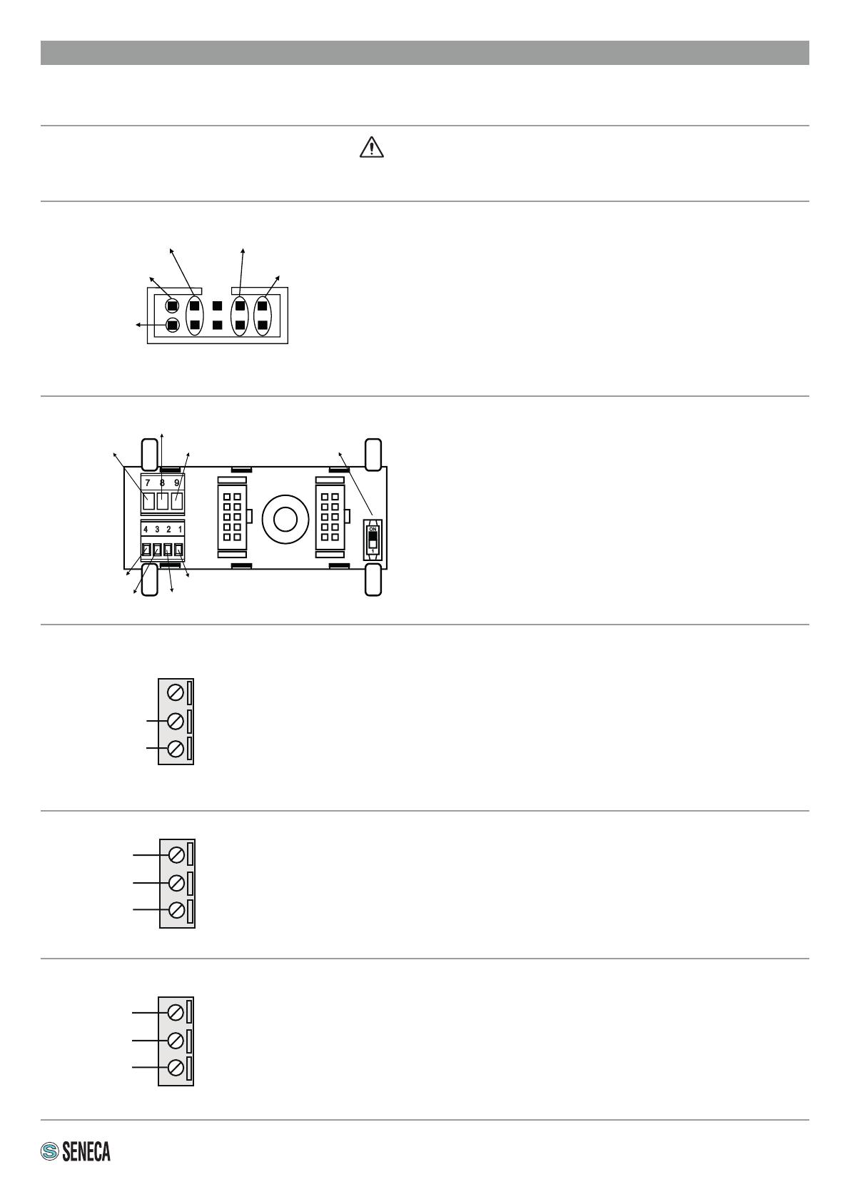
Z-PC-DINAL2-17.5 accessory use
If the Z-PC-DINAL2-17.5 accessory is used, signals
can be sent via terminal boards. The illustration
shows the meaning of the various terminals and
DIP-switch position (found in all supports for the DIN
rail listed in Accessories) for the termination of the
CAN network (not used for the Modbus network).
GNDSHLD:
Connection cable signal protection shield
(recommended).
Power supply
Terminals 2 and 3 can be used to provide the module with power supply as an
alternative to the connection using the Z-PC-DINx bus.
The power supply voltage must remain in the range of either 19 and 40V Vdc (any
polarity), or 19 and 28V Vac.
The upper limits must not be exceeded as this can seriously damage the
module.
If the power supply source is not protected against overload, a safety fuse with a 1 A
max permissible value must be installed in the power supply line.
Serial port 2: RS485 SW2 = OFF
Z- KEY WIFI has a serial port that can be set with the SW2 switch.
If switch SW2 is in the OFF position, the RS485 COM 2 port is available at terminals
10-11-12. The illustration shows how to complete connections.
N.B.: the indication of the RS485 connection polarity is not standardised and in some
devices may be inverted.
1
2
3
10
11
12
Serial port 2: RS232 SW2 = ON
Z- KEY WIFI has a serial port that can be set with the SW2 switch.
If switch SW2 is in the ON position, the RS232 COM 2 port is available at terminals
10-11-12.
The illustration shows how to complete connections.
The RS232 interface is fully settable.
10
11
12
GND
A (+)
B (-)
GND
RX
TX
Vac/Vdc
Vac/Vdc
Use only copper or copper-clad aluminium or AL-CU or CU-AL conductors
ATTENTION
6/7
COMMUNICATION PORT IDENTIFICATION
RJ45 Ethernet port (on front)
Z-KEY-wi has an Ethernet 100 port with RJ45 connector on the
module front.
Micro USB port
Z-KEY-wi has a USB connector that can be used as a
conguration port via the Easy Setup software.
Micro SD card slot
Z-KEY-WIFI has a micro SD card slot on the side of the case.
To insert the SD card in the corresponding slot, make sure the
metal contacts are facing right (as shown in the side gure).
The SD card can be of any capacity.
To activate the rst conguration Access Point function, follow the following steps:
1. Press the side button of the Z-KEY-WIFI;
2. Keeping the button pressed, power the instrument;
3. Release the button after 5 seconds.
Through this procedure, the device switches to rst conguration AP mode without password to enter the
parameters of the WIFI. The AP led will ash.
ACCESS POINT: FIRST CONFIGURATION
OPERATION IN ACCESS POINT MODE
In this mode, a device can function as an Access Point and accept the connection of up to 6 station devices
without the aid of an external Access Point.
This conguration can be activated from the web server.
OPERATION IN STATION MODE
In this mode, the device can connect to an existing Access Point. This function can be activated from the web
server.
7/7
Z-KEY-WIFI can be fully set up via integrated web server.
The product programming tools can be downloaded free of charge from www.seneca.it, in the Z- KEY-WIFI section.
To access the conguration, connect with a browser to the maintenance page at the IP address of the Z-KEY-WIFI, for
example: http://192.168.90.101 and, when requested, enter the following credentials: Username: admin Password: admin.
in the Z-KEY-WIFI section.
FOR FURTHER INFORMATION, REFER TO THE USER MANUAL available for download at www.seneca.it in the
Z-KEY-WIFI section.
INSTRUMENT CONFIGURATION
CONTACT INFORMATION
Technical support [email protected] Product information [email protected]
This document is the property of SENECA srl. Copies and reproduction are prohibited unless authorised.
The content of this document corresponds to the described products and technologies.
Stated data may be modied or supplemented for technical and/or sales purposes.
  • Page 1 1
  • Page 2 2
  • Page 3 3
  • Page 4 4
  • Page 5 5
  • Page 6 6
  • Page 7 7
  • Page 8 8

Seneca Z-KEY-WIFI Installation guide

Type
Installation guide

Seneca Z-KEY-WIFI is a gateway module and serial device server with Wi-Fi capabilities, allowing for flexible data transmission and communication in various industrial applications. Its compact design and DIN rail mounting make it easy to integrate into existing systems. With built-in RS485 and RS232 serial ports, Z-KEY-WIFI can connect to a wide range of industrial devices, enabling remote monitoring and control. Additionally, the Ethernet port and Wi-Fi connectivity provide versatile networking options for data transmission over wired or wireless networks.

Ask a question and I''ll find the answer in the document

Finding information in a document is now easier with AI