MI00362-6-EN INSTALLATION MANUAL 3/4
INPUTS
Voltage input:Bipolar with F.S. programmable at +2Vdc and +10Vdc Input impedance >100kOhm
Current input: Bipolar with F.S. Programmable at +20mA with 50Ohm internal shunt selectable via
DIP-switch. Available power supply: 90 + 90mA at 13Vdc.
Number of channels: 8
Input resolution: 15 bit + sign.
Input protection: ± 30Vdc or 25mA
Precision
voltage and
current:
Starting: 0.1 of full scale
Linearity : 0.03% of scale.
Zero: 0.05% of scale.
TC: 100 ppm, EMI: <1 %
Sampling time 120 ms/channel or 60 ms/channel
Measurement update time
(sampling rate: 10ms)
1 channel enabled (update time for 1 channel)
4 channels enabled (update time for 4 channels)
8 channels enabled (update time for 8 channels)
CONFIGURATION OF FACTORY SETTINGS
All DIP-switches in OFF position
Communication parameters of ModBUS protocol: 38400 8, N, 1 Address 1
Communication parameters of micro USB front port 2400 8, N, 1 Address 1
Channel input from 1 to 8: VOLTAGE ± 10Vdc
Numerical representation of the input measurement: ± 10000mV
Sampling time: 120ms
Note: When DIP switches 1 to 8 are OFF, the communication settings are taken from programming (EEPROM).
Note 2: The RS485 line must be terminated only at the ends of the communication line.
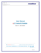
SETTING THE DIP-SWITCHES
The position of the DIP-switches denes the Modbus communication parameters of the module: Address and Baud Rate
The following table shows the Baud Rate and Address values according to the
DIP-switch
setting:
DIP-Switch status
SW1 POSITION BAUD
RATE
SW1 POSITION ADDRESS POSITION TERMINATOR
1 2 3 4 5 6 7 8 3 4 5 6 7 8 10
9600 #1 Disabled
19200 #2 Enabled
38400 #...
57600 #63
From
EEPROM
From
EEPROM
LEGEND
ON
OFF
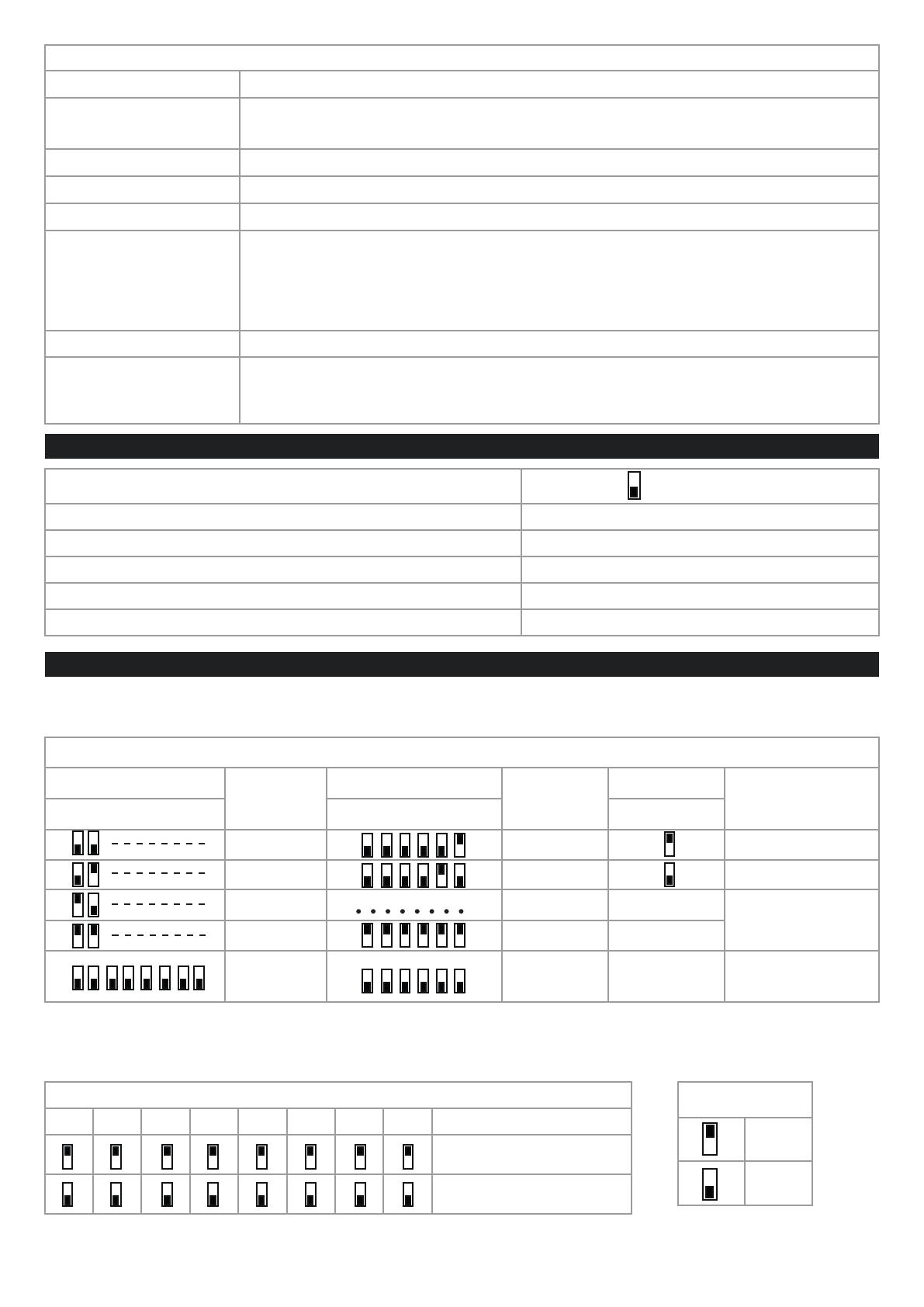
SW2 ANALOG INPUT
12345678 CHANNEL
CURRENT INPUT
VOLTAGE INPUT
The settings of the dip-switches must be compatible with the settings on the registers. The description of the registers is
available in the USER MANUAL.